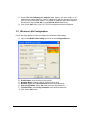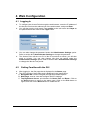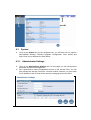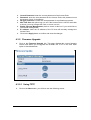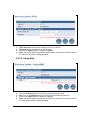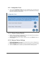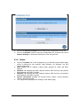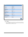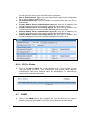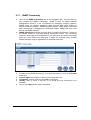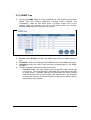
1
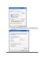
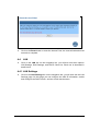
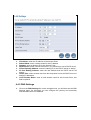
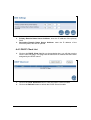
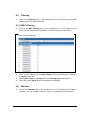
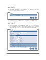
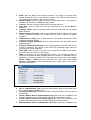
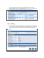
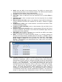
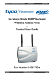
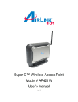
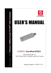
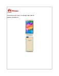
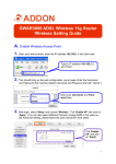
Dual Band Wireless
A+G Access Point
User’s Manual
Version: 1.1
Table of Contents
Chapter 1 – Introduction………………………………..…………………………….4
1.1 Features & Benefits………………………………………………………………..4
1.2 Package Contents………………………………………………………………….5
Chapter 2 – Understanding the Hardware…………………………..……….5
2.1 Hardware Configuration………………………………………………………...…5
2.2 Hardware Installation………………………………………………………………5
Chapter 3 – PC Configuration……………………………….……………………..5
3.1 TCP/IP Configuration………………………………………………………………5
3.2 Wireless LAN Configuration………………………………………………....……7
Chapter 4 – Web Configuration……………………..…………………………….8
4.1 Logging In………………………………..………………………………………..……….8
4.2 Getting Familiar with the GUI………………………………..…..…………………….8
4.3 System…………..………………………………..……………………………………….8
4.3.1 Administrator Settings………………..……………..…………………………….9
4.3.2 Firmware Upgrade………………………………………………..……………..10
4.3.2.1 Using TFTP……………………….……………………………...………...10
4.3.2.2 Using Web……………………………………..…………………………….11
4.3.3 Configuration Tools……………………………………..……………………...….12
4.3.3.1 Restore Factory Defaults……………………………………..…….…….12
4.3.3.2 Backup / Restore Settings……………………………………..…...…….12
4.3.4 Status……………………………………..………………………………………….13
4.3.5 Reset……………………………………..………………………………….……….14
4.4 LAN…………………….……………………..…………..…………………………….15
4.4.1 LAN Settings………………………………………..……………………..……….15
4.4.2 DNS Settings………………………………………………..…………………….16
4.4.3 DHCP Client List……………………………………..…………………………….17
4.5 Filtering……………………………………………..………………………………...….18
4.5.1 MAC Address Filtering……………………………..…………………………….18
4.6 Wireless……………………………………..…………………..……………………….18
4.6.1 General……………………………………..……………………………………….19
4.6.2 802.11a……………………………………..……………………………………….19
4.6.3 802.11g……………………………………..……………………………………….21
4.6.4 802.1x status……………………………………..…………………..…………….23
4.7 SNMP……………………………………..………………………………...…………….23
4.7.1 SNMP Community…………………………………..…………………………….24
4.7.2 SNMP Trap…………………………………..……………………………..……….25
Page 2 of 25
Revision History
Version
Date
Notes
1.0
1.1
August 26, 2003
September 3, 2003
Initial Version
Updated web screens
Page 3 of 25
1 Introduction
The Dual Band Wireless A+G Access Point operates seamlessly and simultaneously
in both the 2.4 GHz and 5 GHz frequency spectrums supporting the 802.11b
(2.4GHz, 11Mbps) and the newer, faster 802.11a (5GHz, 54Mbps) and 802.11g
(2.4GHz, 54Mbps) wireless standards. It's the best way to add wireless capability to
your existing wired network, or to add bandwidth to your wireless installation.
To protect your wireless connectivity, the Dual Band Wireless A+G Access Point can
encrypt all wireless transmissions through 64/128/152-bit WEP data encryption. The
MAC address filter lets you select exactly which station has access to your wireless
network. Dynamic Frequency Selection (DFS) puts your network on the cleanest
channel in your location. With the Dual Band Wireless A+G Access Point, you'll
experience the best wireless connectivity available today.
1.1
Features & Benefits
Features
Dual Radios for 802.11a and 802.11g / b
3-way bridging for 802.3 / 802.11a /
802.11g networks
High speed data rate up to 54 Mbps / 108
Mbps in “Turbo” mode (11a mode)
Up to 152-bit WEP data encryption
Wi-Fi protected Access / IEEE 802.1x /
RADIUS Client (EAP-MD5 / TLS / TTLS)
support
Transmission Power Control (TPC)
support
Dynamic Frequency Selection (DFS)
support
Wireless client MAC address filtering
SNMP / Telnet / Web configuration
Firmware upgradeable through Telnet /
Web-browser / Console
DHCP Server / DNS Relay
Benefits
The 802.11a and 802.11g wireless LANs
can be used simultaneously.
Enables the transfer of data among
different kinds of networks.
Capable of handling heavy data payloads
such as MPEG video streaming.
Powerful data security.
Enhances authentication and security.
Offers flexibility to adjust RF output power.
Provides flexible selection of the best
frequency to allow mobility among all
existing IEEE 802.11a / b / g networks.
Ensure secure network connections.
Helps administrators remotely configure or
manage the device via SNMP, Telnet, or a
web-browser.
Easy to upgrade firmware reduces
operations overhead.
Powerful routing support enables
segmentation and routing of IP protocols.
Page 4 of 25
1.2
Package Contents
h
h
h
h
h
h
One Access Point
One Power Adapter
One CAT 5 UTP Cable
One RS-232 Cable
One Fast Start Guide
One CD-ROM with User’s Guide Included
2 Understanding the Hardware
2.1 Hardware Configuration
h
h
h
h
RJ-45 Ethernet Connector – Provides 10/100 Mbps connectivity to a
wired Ethernet LAN.
RS-232 Console Connector – Provides Command Line Interface (CLI) to
view and modify the configuration of the AP from a terminal or PC through
a telnet connection.
Reset Button – By holding this down for more than five seconds, the AP
will reset to its factory default settings.
Power Supply Connector – Connects to the power adapter.
2.2 Hardware Installation
A. Configure your notebook or PC with a wireless LAN card.
B. For a wired LAN, connect your PC’s Ethernet port to the AP’s LAN port via an
Ethernet cable.
C. For WLAN, position the Access Point in a proper position.
D. Plug in the power cord into the power outlet.
3 PC Configuration
3.1 TCP/IP Configuration
Follow the steps below in order to configure the TCP/IP settings of your PC.
A. In the Control Panel double click Network Connections, and then double
click on the connection of your Network Interface Card (NIC). You will then
see the following screen.
Page 5 of 25
B. Select Internet Protocol (TCP/IP) and then click on the Properties button.
This will allow you to configure the IP address of your PC. You will then see
the following screen.
Page 6 of 25
C. Select Use the following IP address radio button, and then enter an IP
address and subnet mask for your PC. Make sure that the Access Point and
your PC are on the same subnet. The default IP address and subnet mask of
the Access Point are 192.168.1.1 and 255.255.255.0 respectively.
D. Click on the OK button, your PC’s TCP/IP settings have been configured.
3.2 Wireless LAN Configuration
Follow the steps below in order to configure the Wireless LAN settings.
A. Launch the WLAN Client Utility and click on the Configuration tab.
B.
C.
D.
E.
F.
G.
Profile Name: enter a name for this profile.
Network Name: enter the SSID. (Default name: Any)
Network Type: select Access Point from the drop-down list.
Power Save Mode: Select Off or On from the drop-down list.
Transmit Rate: select Fully Automatic from the drop-down list.
Click on the OK button.
Page 7 of 25
4 Web Configuration
4.1 Logging In
h
To configure the Access Point through the web-browser, enter the IP address of
the Access Point into the address bar of the web-browser, and press Enter.
You will then see the login page. Enter admin as the user name and iktpw as
the password and then click on the Login button.
h
h
You can also change the password under the Administrator Settings option.
Refer to section 4.3.1 Administrator Settings to change the password.
The Access Point will time out if it is idle for more than a minute, you will then
need to re-login. You can also change idle time out period under the
Administrator Settings option. Refer to section 4.3.1 Administrator Settings
to change the idle time out period.
h
4.2
h
h
Getting Familiar with the GUI
After logging in, the first page that is displayed in the Status page.
The GUI consists of three parts and is displayed in the image below:
A. Navigation Bar: used to navigate through the available options.
B. Main Page: used to view and configure the AP’s settings.
C. Top Right-hand Corner: quick buttons for Home, Exit, and Reset. Click on
the Home button to return to the status page. Click on the Exit button to
logout, and click on the Reset button to restart the AP.
Page 8 of 25
C
B
A
4.3
h
System
Click on the System link on the navigation bar, you will then see five options:
Administrator Settings, Firmware Upgrade, Configuration Tools, Status, and
Rest. Each one is described in detail below.
4.3.1 Administrator Settings
h
h
Click on the Administrator Settings link. On this page you can configure the
password and remote management.
Set a password to restrict management access to the Access Point. You can
also manage the Access Point from a remote location; however you must enter
the IP address of the PC that will be remotely managing the Access Point.
Page 9 of 25
h
h
h
h
h
h
h
Current Password: enter the current password of the Access Point.
Password: enter the new password for the Access Point; this password must
be between 3 and 12 characters.
Re-type password: re-enter the new password for confirmation purposes.
Idle Time Out: this option logs you out if the Access Point is idle for more than
a minute, you may change this value, or leave it as it is.
Enable Remote Management: place a check in this box if you would like to
use remote management.
IP address: enter the IP address of the PC that will remotely manage the
Access Point.
Click on the Apply button to confirm and save the changes.
4.3.2 Firmware Upgrade
h
Click on the Firmware Upgrade link. This page displays the current firmware
version and allows you to upgrade the firmware via TFTP or the web. Each
option is described below.
4.3.2.1 Using TFTP
h
Click on the Next button, you will then see the following screen.
Page 10 of 25
h
h
h
h
TFTP Server IP: enter the IP address of the TFTP Server.
Filename: enter the filename of the firmware.
Click on the Apply button to begin the upgrade.
Note: the whole upgrade procedure takes about 3 minutes, do not power off the
AP while the firmware is being upgraded.
4.3.2.2 Using Web
h
h
h
h
Click on the Next button, you will then see the following screen.
File: click on the Browse button, and select the firmware upgrade file.
Click on the Apply button to begin the upgrade.
Note: the whole upgrade procedure takes about 3 minutes, do not power off the
AP while the firmware is being upgraded.
Page 11 of 25
4.3.3 Configuration Tools
h
Click on the Configuration Tools link on the navigation bar, you will then see
two options: Restore Factory Default Configuration and Back/Restore Settings.
Each one is described in detail below.
4.3.3.1 Restore Factory Defaults
h
h
Restore Factory Default Configuration forces the Access Point to perform a
reset and restore the original factory settings.
Click on the Next button to continue, and then click on the Restore button on
the next page.
4.3.3.2 Backup / Restore Settings
h
h
h
Backup Settings allows you to save the Access Point’s current configuration to
a file named config.bin on you PC.
Restore Settings is used to restore the saved configuration to the Access Point.
Click on the Next button to continue, you will then see the following screen.
Page 12 of 25
h
h
Click on the Backup Settings button to backup the configuration on your PC.
Click on the Browse button to select the configuration file, and then click on the
Restore Settings to restore the backup file on the Access Point.
4.3.4 Status
h
h
h
h
h
h
Click on the Status link on the navigation bar, you will then see the Status page
which is divided into four sections: LAN, Wireless 11a, Wireless 11g, and
System Information.
LAN: displays the IP address, subnet mask, gateway IP, DNS, and MAC
address.
Wireless 11a: displays the SSID, channel number, WEP security, and wireless
MAC address of the 802.11a radio.
Wireless 11b: displays the SSID, channel number, WEP security, and wireless
MAC address of the 802.11g radio.
System Information: displays the Access Point’s uptime, current firmware
version, and serial number.
The image below displays some settings on the Status page.
Page 13 of 25
4.3.5 Reset
h
Click on the Reset link on the navigation bar, you will then see the Reset page.
After you change any settings or in the even that the Access Point stops
responding correctly, you can perform a reset.
Page 14 of 25
h
4.4
h
Click on the Reset button to reset the Access Point, the reset will take about 40
seconds to complete.
LAN
Click on the LAN link on the navigation bar, you will then see three options:
LAN Settings, DNS Settings, and DHCP Client List. Each one is described in
detail below.
4.4.1 LAN Settings
h
Click on the LAN Settings link on the navigation bar, you will then see the LAN
Settings page. On this page you can configure the LAN IP information, enable
and configure the DHCP server, and set a local domain name.
Page 15 of 25
h
h
h
h
h
h
h
h
IP Address: enter the IP address of the Access Point.
Subnet Mask: enter a subnet mask for the IP address.
Gateway: enter a gateway IP for the Access Point.
DHCP Server: place a check in this box if you would like to use a DHCP server.
IP Pool Starting Address: enter the starting IP for the DHCP server to assign.
IP Pool Ending Address: enter the last address that the DHCP server will
assign.
Lease Time: select a lease time from the drop-down list for the DHCP server to
assign IP addresses.
Local Domain Name: enter a local domain name for this Access Point; this
field is optional.
4.4.2 DNS Settings
h
Click on the DNS Settings link on the navigation bar, you will then see the DNS
Settings page. On this page you can configure the primary and secondary
Domain Name Server IP address.
Page 16 of 25
h
h
Primary Domain Name Server Address: enter the IP address of the primary
DNS.
Secondary Domain Name Server Address: enter the IP address of the
secondary DNS; this field is optional.
4.4.3 DHCP Client List
h
Click on the DHCP Client List link on the navigation bar, you will then see the
DHCP Client List page. This page lists the MAC and IP address that have been
assigned by the DHCP server.
h
h
Click on the Clear & Restart button to clear the DHCP Client List table.
Click on the Refresh button to refresh the CHCP Client List table.
Page 17 of 25
4.5
h
Filtering
Click on the Filtering link on the navigation bar, you will then see the MAC
filtering option, as described below.
4.5.1 MAC Filtering
h
Click on the MAC Filtering link on the navigation bar. On this page you can
allow or reject specific MAC addresses from accessing the Access Point.
h
Enter a MAC address into the MAC address field, and then place a check in
the Select check box.
Select Allow, Reject, or Disable from the Filtering Type drop-down list.
Then click on the Apply button at the bottom of the page.
h
h
4.6
h
Wireless
Click on the Wireless link on the navigation bar, you will then see four options:
General, 11a, 11g, and 802.1x status. Each one is described in detail below.
Page 18 of 25
4.6.1 General
h
Click on the General link on the navigation bar. On this page you can select
and set the country for the Access Point.
h
Select a country from the drop-down list, and then click on the Apply button.
4.6.2
h
802.11a
Click on the 11a link on the navigation bar. On this page you can configure the
802.11a settings. This page is divided into four sections: General, Advanced
Setting, WEP, and 802,1x. Each section is described below with an image.
Page 19 of 25
h
h
h
h
h
h
h
h
h
h
h
h
h
h
h
h
SSID: enter the SSID of the wireless network. The SSID is a unique name
shared among all points in your wireless network. The SSID must be identical
for all points in the network, and is case-sensitive.
Wireless Mode: select a data rate from the drop-down menu. One option is
54Mbps and the other is 108Mbps in turbo mode.
Channel: select a frequency channel from the drop-down list.
Data Rate: select a data rate from the drop-down list; by default Best is
selected.
Transmit Power: select a transmit power from the drop-down list; by default
full is selected.
Beacon Interval (20-1000): enter a value between 20 and 1000 for the beacon
interval. Beacons announce the existence for the 802.11 network at regular
intervals.
DTIM Interval (1-255): enter a value between 1 and 255 for the Deliver Traffic
Indication Message (DTIM).
Fragment Length (256-2346): enter a value between 256 and 2346 for the
fragment length.
RTS/CTS Threshold (256-2346): enter a value between 256 and 2346 for the
RTS/CTS threshold. Any packet in the RTS/CTS handshake larger than the
specified size will be discarded.
Hide SSID: place a check in this box if you would like the SSID to be hidden
from other Access Points or a site survey.
WEP: an acronym for Wired Equivalent Privacy is a security protocol for
Wireless Local Area Network (WLANs) defined in the 802.11 standard. WEP is
designed to provide the same level of security as a wired LAN. Select none,
64-bit, 128-bit or 152-bit from the drop down list. Then select either Open
System or Shared-key for the authentication type. Finally, enter a key value in
one of the text boxes.
802.1x Authentication Type: select an authentication type from the drop-down
list, or select none to disable 802.1x.
Re-authentication time: enter the number of seconds before the user can reauthenticate.
Primary Radius Server Authentication Server IP: enter the IP address, port
number and shared secret of the primary RADIUS authentication server.
Primary Radius Server Accounting Server IP: enter the IP address, port
number and shared secret of the primary RADIUS accounting server.
Backup Radius Server Authentication Server IP: enter the IP address, port
Page 20 of 25
h
number and shared secret of the backup RADIUS authentication server.
Backup Radius Server Accounting Server IP: enter the IP address, port
number and shared secret of the backup RADIUS accounting server.
4.6.3
h
802.11g
Click on the 11g link on the navigation bar. On this page you can configure the
802.11g settings. This page is divided into four sections: General, Advanced
Setting, WEP, and 802,1x. Each section is described below with an image.
Page 21 of 25
h
h
h
h
h
h
h
h
h
h
h
SSID: enter the SSID of the wireless network. The SSID is a unique name
shared among all points in your wireless network. The SSID must be identical
for all points in the network, and is case-sensitive.
Channel: select a frequency channel from the drop-down list.
Data Rate: select a data rate from the drop-down list; by default Best is
selected.
Transmit Power: select a transmit power from the drop-down list; by default
full is selected.
Beacon Interval (20-1000): enter a value between 20 and 1000 for the beacon
interval. Beacons announce the existence for the 802.11 network at regular
intervals.
DTIM Interval (1-255): enter a value between 1 and 255 for the Deliver Traffic
Indication Message (DTIM).
Fragment Length (256-2346): enter a value between 256 and 2346 for the
fragment length.
RTS/CTS Threshold (256-2346): enter a value between 256 and 2346 for the
RTS/CTS threshold. Any packet in the RTS/CTS handshake larger than the
specified size will be discarded.
Hide SSID: place a check in this box if you would like the SSID to be hidden
from other Access Points or a site survey.
WEP: an acronym for Wired Equivalent Privacy is a security protocol for
Wireless Local Area Network (WLANs) defined in the 802.11 standard. WEP is
designed to provide the same level of security as a wired LAN. Select none,
64-bit, 128-bit or 152-bit from the drop down list. Then select either Open
System or Shared-key for the authentication type. Finally, enter a key value in
one of the text boxes.
The 802.1x standard is designed to enhance the security of WLANs that follow
IEEE 802.11 standards. 802.1x uses an existing protocol called Extensible
Authentication Protocol (EAP) for message exchange during the authentication
process. In a WLAN with 802.1x, a user requests access to the access point
(known as the authenticator). The access point forces the user into an
unauthorized state that allows the client to send only an EAP-start message.
The AP replies with an EAP-request identify message to obtain the clients
identity. The clients EAP-response packet containing the clients identity is
forwarded to the authentication server. The authentication server is configured
to authenticate clients with a specific authentication algorithm. The result is an
accept or reject packet from authentication server to AP. Once authenticated,
Page 22 of 25
h
h
h
h
h
h
the AP opens the client’s port and traffic will be forwarded
802.1x Authentication Type: select an authentication type from the drop-down
list, or select none to disable 802.1x.
Re-authentication time: enter the number of seconds before the user can reauthenticate.
Primary Radius Server Authentication Server IP: enter the IP address, port
number and shared secret of the primary RADIUS authentication server.
Primary Radius Server Accounting Server IP: enter the IP address, port
number and shared secret of the primary RADIUS accounting server.
Backup Radius Server Authentication Server IP: enter the IP address, port
number and shared secret of the backup RADIUS authentication server.
Backup Radius Server Accounting Server IP: enter the IP address, port
number and shared secret of the backup RADIUS accounting server.
4.6.4 802.1x Status
h
4.7
h
Click on the 802.1x status link on the navigation bar. On this page you can
view the status of 802.1x. This includes the port number, MAC address,
authentication PAE state, backend state, Rx frames/bytes, Tx frames/bytes,
session time, and last session time.
SNMP
Click on the SNMP link on the navigation bar, you will then see two options:
SNMP Community and SNMP Trap. Each one is described in detail below.
Page 23 of 25
4.7.1 SNMP Community
h
h
h
h
h
h
h
Click on the SNMP Community link on the navigation bar. On this page you
can configure the SNMP Community. SNMP is short for Simple Network
Management Protocol, a set of protocols for managing complex networks.
SNMP works by sending messages called Protocol Data Units (PDUs) to
different parts of a network. SNMP-compliant devices, called agents, store data
about themselves in Management Information Bases (MIBs) and return this
data to the SNMP requests.
SNMP Community provides a simple kind of password protection. Access to
the SNMP device is controlled through community names. The community
name can be thought of as a password. If you don’t have the correct community
name you can’t retrieve any data (get) or make any changes (sets). Multiple
SNMP managers may be organized in a specified community.
In order to use SNMP Community, you must first place a check in the Enable
check box.
Access Right: select Read or Write from the drop-down list.
Community: enter a name for the SNMP Community.
Validity: place a check in this box if you would like that community to be
available.
Click on the Apply button when completed.
Page 24 of 25
4.7.2 SNMP Trap
h
Click on the SNMP Trap link on the navigation bar. This Access Point receives
SNMP Traps from network equipment, including routers, switches, and
workstations. Traps are sent when errors or specific events occur on the
network. Traps are normally only sent to end stations which are currently
sending SNMP requests to the device in question.
h
Version: select Disable to disable the SNMP trap function or SNMP version 1
or 2.
IP Address: enter the IP address of the SNMP server for the SNMP trap report.
Community: enter the name of the community (public/private) for the SNMP
manager.
The following trap is supported in the Access Point:
o Cold-start Trap: this trap indicates that the specified node’s power has
just come on. The Cold-start trap is generated every time the Access Point
is power-cycled. Cold-start traps are not generated until three seconds
after the Access Point is power-cycled. This allows time for the hardware
providing the low-level IP network interface to start-up and stabilize before
attempting to send a packet.
h
h
h
Page 25 of 25