1
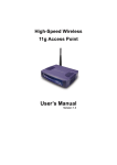
Wireless Access Point Model 0-1591700-x
User Manual
Page 1 of 33
Corporate Grade SNMP Managed
Wireless Access Point
Product User Guide
Part Number 0-1591700-x
PL0356
©2003TycoElectronics
Issue 1
Wireless Access Point Model 0-1591700-x
User Manual
Page 2 of 33
Table Of Contents
Introduction........................................................................................................................4
Key Features and Benefits .......................................................................................................... 4
Supplied Items............................................................................................................................. 4
FCC Compliance ......................................................................................................................... 5
Declaration of Conformity ............................................................................................................ 5
Other Regulatory Statements ...................................................................................................... 5
General Operational Requirements.......................................................................................... 5
Operation of IEEE802.11a 5GHz Radio in the European Community ...................................... 5
5GHz Channel Assignments In Europe.................................................................................... 5
2.4GHz Channel Assignments In Europe................................................................................. 5
Other 5GHz Channel Assignments .......................................................................................... 5
Other 2.4GHz Channel Assignments ....................................................................................... 5
Disclaimer ................................................................................................................................... 6
Support ....................................................................................................................................... 6
Warranty...................................................................................................................................... 6
Installation Practice ...........................................................................................................7
Do I Need A Site Survey ? ....................................................................................................... 7
Location Guidelines ................................................................................................................. 7
WLAN Security............................................................................................................................ 7
Access Point Ports ...................................................................................................................... 8
DC In ....................................................................................................................................... 8
LAN ......................................................................................................................................... 8
RS232...................................................................................................................................... 8
Reset ....................................................................................................................................... 8
LED Indicators............................................................................................................................. 8
Wall Mounting the Access Point .................................................................................................. 9
Desk Mounting the Access Point ................................................................................................. 9
Unit Information ........................................................................................................................... 9
Product Part Number ............................................................................................................... 9
Unit Serial Number................................................................................................................... 9
MAC Addresses....................................................................................................................... 9
Getting Started.................................................................................................................10
Configuring your PC .................................................................................................................. 10
Connecting To The Access Point .............................................................................................. 11
Menu Systems..................................................................................................................14
Web Browser Menu................................................................................................................... 14
Serial Console Menu ................................................................................................................. 14
Telnet Menu .............................................................................................................................. 14
System Menu....................................................................................................................15
Administrator Settings ............................................................................................................... 15
Password Settings ................................................................................................................. 15
Idle Time Out ......................................................................................................................... 15
Remote Management ............................................................................................................ 15
Firmware Upgrade..................................................................................................................... 16
TFTP Upgrade ....................................................................................................................... 16
Web Upgrade......................................................................................................................... 17
Configuration Tools ................................................................................................................... 17
Restore Factory Default Configuration ................................................................................... 17
Backup Settings / Restore Settings........................................................................................ 18
Status........................................................................................................................................ 18
Reset......................................................................................................................................... 18
PL0356
©2003TycoElectronics
Issue 1
Wireless Access Point Model 0-1591700-x
User Manual
Page 3 of 33
LAN Menu .........................................................................................................................19
LAN Settings ............................................................................................................................. 19
IP Address ............................................................................................................................. 19
DHCP Settings....................................................................................................................... 19
DNS Settings............................................................................................................................. 20
DHCP Client List ....................................................................................................................... 20
Filtering Menu ..................................................................................................................21
MAC Address Filtering - Access Control List ............................................................................. 21
Wireless Menus................................................................................................................22
11a Menu Option....................................................................................................................... 22
SSID ...................................................................................................................................... 22
Wireless Mode ....................................................................................................................... 22
Smart Channel....................................................................................................................... 23
Channel ................................................................................................................................. 23
Advanced Settings .................................................................................................................... 23
Radio On/Off.......................................................................................................................... 23
Data Rate .............................................................................................................................. 23
Transmit Power...................................................................................................................... 23
Beacon Interval...................................................................................................................... 23
DTIM Interval ......................................................................................................................... 23
Fragment Length ................................................................................................................... 24
RTS/CTS Threshold............................................................................................................... 24
Hide SSID.............................................................................................................................. 24
Authentication ........................................................................................................................... 24
Authentication Type ............................................................................................................... 24
WEP Encryption..................................................................................................................... 24
802.1X ................................................................................................................................... 25
Re-authentication Time.......................................................................................................... 25
Primary Radius Server – Authentication Server IP................................................................. 25
802.11g Menu Option ................................................................................................................ 26
Channel ................................................................................................................................. 26
Short Preamble...................................................................................................................... 26
802.11g Stations Only............................................................................................................ 27
Protection Mode..................................................................................................................... 27
Protection Rate ...................................................................................................................... 27
Protection Type...................................................................................................................... 27
Short Slot Time ...................................................................................................................... 27
Status Menu Option................................................................................................................... 28
802.1x Status ............................................................................................................................ 28
SNMP Menu ......................................................................................................................29
SNMP Community..................................................................................................................... 29
Item ....................................................................................................................................... 29
Access Right.......................................................................................................................... 29
Community ............................................................................................................................ 29
Validity ................................................................................................................................... 29
SNMP Trap ............................................................................................................................... 30
Item ....................................................................................................................................... 30
IP Address ............................................................................................................................. 30
Community ............................................................................................................................ 30
Generated Traps.................................................................................................................... 30
SNMP MIB Support ................................................................................................................... 30
Fault-Finding and FAQs ..................................................................................................31
Power Supplies ......................................................................................................................... 32
Product Specifications ....................................................................................................33
PL0356
©2003TycoElectronics
Issue 1
Wireless Access Point Model 0-1591700-x
User Manual
Page 4 of 33
Introduction
The Tyco Electronics Wireless Access Point model 0-1591700 is an SNMP managed, dual band,
multimode high performance access point intended for the professional, commercial and corporate
markets. The access point provides simultaneous, high-speed support for all three current wireless
modes (802.11a, b and g) using both the 2.4GHz and 5GHz commercial wireless bands. This high
level of wireless flexibility delivers a product that is ideal for environments such as offices where
there are highly mobile workers who may have different wireless client products. In addition to
future-proofed wireless support, the access point supports all the corporate standards for security
including WEP, WPA* and 802.1x RADIUS log-ins. Management is very important for corporate
systems and the access point supports web, Telnet, console and SNMP management interfaces.
The complexity of wireless networks is hidden by the access point that provides a set of clear
menus that easily and quickly guides new users through the configuration process. The installation
process is described in the Getting Started Guide on page 10 onwards and also in more detail in
the Main Section of this manual.
Key Features and Benefits
Supports simultaneous operation of 802.11b
and 802.11g and 802.11a radio modes
Supports high level security options:• 802.1x Authentication with RADIUS
• WPA*
• WEP with 64/128 and 152 bit keys
• MAC Access Control List locking
• Hidden SSID option
Excellent performance radios with both high
power transmitters and high sensitivity receivers
Supports all FCC approved channels
Delivers a high level of future-proofing with
support for all current WLAN modes and bands
Delivers corporate grade security with industry
leading security facilities that enable the access
point to be safely used in higher risk areas.
Enables the access point to serve wide areas
Enables the access point to be used in very
congested radio environments
Supports Transmit Power Control and Dynamic Enables the access point to be used in Europe
Frequency Selection
and delivers transmit power management to suit
the radio environment.
Supports SNMP, Telnet, Web and Console Greatly simplifies configuration and operational
interfaces
management of the access points in a corporate
environment
Optional DC injector, supports power over the Eliminates the need for an AC power cube close
Ethernet cable
to the access point. This greatly simplifies
installation and allows access points to be
located far away from AC mains points.
* = WPA security available in Code Release 3.x in Q1 2004.
Supplied Items
The access point is supplied in a cardboard carton which contains the following:a) Installation Manual
b) Wireless Access Point
c) AC Power Adapter
d) Stand for the Access Point
e) Ethernet Data Cross-over Cable for local configuration via a PC
f) RS232 Serial Console Cable
If the package does not contain these items, please consult your distributor.
PL0356
©2003TycoElectronics
Issue 1
Wireless Access Point Model 0-1591700-x
User Manual
Page 5 of 33
FCC Compliance
This device complies with Part 15 of the FCC rules. Operation is subject to the 2 conditions:1. This device may not cause harmful interference,
2. This device must accept any interference received including interference that may cause
undesired operation.
Declaration of Conformity
Tyco Electronics declare that this product 0-1591700-x is in compliance with the essential
requirements and other relevant provisions of R&TTE Directive 1999/5/EC. For evaluation of
compliance with the Directive, the following standards were applied:o ETSI EN 300 328-2 (07-2000)
o ETSI EN 301 893 (01-2001)
o ETSI EN 301 489-1 (07-2000)
o ETSI EN 301 489-17 (09-2000)
Other Regulatory Statements
General Operational Requirements
1. Ensure that the correct channels and band implemented for the country of usage. The current
channel settings for various countries are listed below and are subject to change.
Operation of IEEE802.11a 5GHz Radio in the European Community
1. The access point is restricted to indoor usage using the channels in the 5.150GHz to 5.350GHz
spectrum (Channels 36 to 64) to reduce the potential for interference.
2. The radio spectrum regulatory bodies in Greece and Spain currently do not permit operation of
the access point in the 5GHz band using IEEE802.11a, however operation in the 2.4GHz band
using IEEE802.11b/g is permitted. To comply with this requirement, the 5GHz band radio must
be disabled as described in page 23.
3. The Access Point supports Dynamic Frequency Selection (DFS) and Transmit Power Control
(TPC) as required for use in Europe.
5GHz Channel Assignments In Europe
Countries of Operation
Austria, France and Switzerland
Denmark, Italy, Germany, Finland, Iceland,
Holland, Norway, Sweden, Portugal, UK, Ireland
Liechtenstein
Permitted 5GHz Band Channels
Channels 36, 40, 44, 48, 52, 56, 60, 64
Channels 36, 40, 44, 48, 52, 56, 60, 64
and 100 to 140
Channels 36, 40, 44, 48
2.4GHz Channel Assignments In Europe
Countries of Operation
All European Community excluding France
France
Permitted 2.4GHz Band Channels
Channels 1 to 13
Channels 10, 11, 12, 13
Other 5GHz Channel Assignments
Countries of Operation
USA and Canada
Permitted 5GHz Band Channels
Channels 36 to 64 and 149 to 161 (pt-pt)
Other 2.4GHz Channel Assignments
Countries of Operation
USA and Canada
Permitted 2.4GHz Band Channels
Channels 1 to 11
Note that the above channel assignment information is subject to change; check with local authorities for details.
PL0356
©2003TycoElectronics
Issue 1
Wireless Access Point Model 0-1591700-x
User Manual
Page 6 of 33
Disclaimer
Tyco Electronics makes no representation or warranties with respect to the contents hereof and
specifically disclaims any implied warranties or merchantability or fitness for any particular
purpose. Further, Tyco Electronics reserves the right to revise this publication and make changes
from time-to-time in the content hereof without obligation of Tyco Electronics to notify any person of
such revision or changes.
Support
The access point is a high performance unit with a very strong feature set. Please carefully check
the manual and the settings of associated equipment before calling for technical support. When
requesting support, please have your proof-of-purchase documentation available.
The first line of support is via the Tyco Electronics web site at www.lan-electronics.com where
further support information and frequently asked questions are located. If you are still unable to
solve the problem then there is a web contact form at www.lan-electronics.com/support.htm that
will assist you in placing the query with us. Please fill in all the fields and provide us with as much
information as possible to assist us in getting a suitable answer to you. The estimated turn-round
time for support requests is 1-2 working days.
Partner level clients may participate in a 24 x 5 telephone helpdesk support scheme.
Warranty
Full details of the generic warranty scheme are available on the web site at:http://www.lan-electronics.com/support.htm
Tyco Electronics (Active LAN Products) warrants this Wireless LAN Access Point product to be
free from defects in material and workmanship, under normal use and operation for a period of 2
years product from the date of purchase from an authorised vendor, subject to the conditions and
exclusions below:1. This warranty does not cover any damage to the products that resulted from accident,
abuse, misuse, natural or personal disaster, or any unauthorised disassembly or
modification, or operation in a manner contrary to the instructions, or shipment of the
product to the Tyco Support Centre.
2. The products are not designed, manufactured or intended for use in hazardous or critical
environments or in activities requiring emergency or fail-safe operation or in any other
activity or application in which failure of the product may pose the risk of physical injury or
death or environmental harm. Tyco Electronics (Active LAN Products) specifically disclaims
any express or implied warranty of fitness for any dangerous application.
3. Except for the foregoing express limited warranty, Tyco makes no other warranty, statutory,
express or implied, including, but not limited to, warranties of merchantability or fitness for a
particular purpose.
4. Tyco Electronics (Active LAN Products) offers a two-year standard warranty to external
power supply. This standard warranty commences from the date that the end Customer
purchases the unit from an authorised vendor.
Submitting A Warranty Claim
Use the Tyco web-based form at http://www.lan-electronics.com/returns_form_normal.htm when
submitting a warranty claim.
PL0356
©2003TycoElectronics
Issue 1
Wireless Access Point Model 0-1591700-x
User Manual
Page 7 of 33
Installation Practice
Wireless LAN systems need a little more planning than conventional wired LANs. This is because
the access point relies on the propagation of radio signals, which are sometimes greatly affected
by a range of factors including:• building materials,
• thickness and type of walls,
• proximity of metal,
• proximity of radar and other high power transmitters
• relative positions and characteristics of client devices.
Do I Need A Site Survey ?
If you are uncertain about the characteristics of an intended location for a wireless LAN system,
then it is advisable to obtain a professional site survey. This will provide a report on the current
radio environment and may also make recommendations about the location of access points.
It is possible to conduct your own informal site survey using the software tools provided on some
client WLAN cards. This is achieved by fitting the appropriate client card into the PC,
commissioning and installing the Access Point in the intended position and then moving the PC
around the intended area. Whilst this is not a scientific method, it does provide a quick method of
determining the likely coverage of an area by observing the relative signal strength.
Note that radio environments may change due to new radars, transmitters, access points and
scientific instrumentation being installed near the access point. This means that further site surveys
may be needed in the future to assist in problem diagnosis.
Location Guidelines
a) Ensure that the number of barriers between the access point and client devices are kept to
the absolute minimum. In an ideal environment, there should be “line-of-sight” between the
access point and the client devices.
b) If the access point and clients are separated by walls, then ensure that the wall is relatively
thin and constructed of a material that is of high radio transparency (not steel or re-inforced
concrete etc).
c) If walls separate the client and the access point, then ensure that the wireless devices are
perpendicular to the walls. This reduces the apparent depth of the wall compared with the
signals needing to pass through a wall at an angle.
d) Reduce the distances between the access point and the client devices to maintain high
signal strengths. This will keep the data transfer rates achieved over the wireless links to
the highest possible levels.
e) Consider the availability of power for the access point. If power is not available, then the DC
Power Injector Model 0-15910710-x can be used to inject power for the access point into
the Ethernet cable at the equipment room. This option enables easy remote powering of
distant access points.
WLAN Security
Wireless access points are potentially a security risk to a network if no precautions are taken.
However as with any network, simple precautions can greatly increase the security of a network to
create a highly secure environment. These precautions include:1. Change the default SSID setting and password (see pages 22 and 26).
2. Hide the SSID value (see page 24)
3. Implement an 802.1x authentication scheme if at all possible (see page 25).
4. If 802.1x cannot be implemented:a. Use the integrated WEP encryption at the highest possible key values and change
the keys on a regular basis (page 24).
b. Use the MAC address based filters (page 21)
5. Place access points on inner walls of a building and use the lowest possible transmit power
settings (see page 23).
PL0356
©2003TycoElectronics
Issue 1
Wireless Access Point Model 0-1591700-x
User Manual
Page 8 of 33
Access Point Ports
The access point has all the physical connections located on the right hand side panel. These
connections are:-
Figure 1 - Access Point Side Panel
DC In
This is a 3.5mm coaxial format jack socket that accepts +12v DC for locally powering the access
point. Ensure that the correct polarity and voltage range is applied.
LAN
This RJ-45 connector is the auto-sensing 10/100Mbps Ethernet circuit that will be connected to the
local switch or other LAN element. For installation, this port is connected to the configuring PC
using the supplied cable. This port is not Auto-MDI/MDI-X and so the correct type of cable is
needed. This port can also be used for powering the access point by the application of +48v DC on
the spare pairs of the structured wiring. See page 32 for details.
RS232
This 9W D-Type connector is the 9600bps serial console link that can be used during configuration
and maintenance activities. The console system uses a command line interface.
Reset
This push-button switch is used to force a factory default reset of the access point. See page 32.
LED Indicators
The access point has 4 LED indicators on the front surface of the unit.
Indicator
Power
LAN
A
B/G
Function
Lights when there is suitable DC power on either the DC In port or on the
RJ-45 Ethernet LAN cable.
Flashes when data is transmitted on the 10/100M Ethernet LAN port
Flashes when data is transmitted on the 802.11a band radio
Flashes when data is transmitted on the 802.11b/g band radio
Note that even if there are no wireless clients associated with the access point, the A and the B/G
LEDs will flash when the access point transmits a beacon frame. See page 23 for details.
PL0356
©2003TycoElectronics
Issue 1
Wireless Access Point Model 0-1591700-x
User Manual
Page 9 of 33
Wall Mounting the Access Point
Figure 2 - Rear Panel
The access point is supplied with a desk-mount stand
but it is probably best to wall-mount the unit to deliver
best possible radio performance.
1. Choose a location that is likely to provide line-ofsight or maximum visibility of the clients in their
intended locations.
2. Ensure that the wall is suitable for drilling and that
there are no major metallic structures in the wall that
may interfere with the radio signals.
3. Consider the powering of the access point and either
provide a local AC socket or use the DC Injector unit
0-1591700-x to down-line power the access point.
4. Drill the mounting surface with 2 holes spaced apart
by 95mm and insert 2 screws into the holes leaving
about 10mm of screw head protruding.
5. Locate the keyhole slots on the rear of the access
point and carefully hang the access point on to the
screw head.
6. Fit the power and LAN cables and position the
antennae vertically as show.
Desk Mounting the Access Point
The access point can be mounted on a desk or similar surface, however it is recommended that
the unit is wall mounted to achieve a more professional installation and reduce the risk of
accidental knocks and other damage that can happened to desk-mounted equipment. The unit is
supplied with a plastic stand that is shaped to accommodate the access point.
1. Ensure that the proposed desk area is safe, dry and clean.
2. Carefully locate the access point into the stand.
3. Connect the cables to the access point.
4. Position the antennae vertically as show.
Unit Information
The rear panel of the access point as shown in Figure 2 has a silver metallic label containing
regulatory information.
Product Part Number
The lower adhesive label contains the Tyco Part Number and will be in the format 0-1591700-x.
Ensure that this full number is quoted on any support requests.
Unit Serial Number
The access point serial number is located on the white adhesive label and is also found on the
System > Status menu option as detailed on page 18.
MAC Addresses
This metallic label has an adhesive label that specifies the MAC address of the Ethernet port of the
access point. The individual MAC addresses for the 802.11a and 802.11b/g radios can be found
from the System > Status menu option as detailed on page 18.
PL0356
©2003TycoElectronics
Issue 1
Wireless Access Point Model 0-1591700-x
User Manual
Page 10 of 33
Getting Started
The access point is easy to install and will work with very little configuration.
Configuring your PC
To enable the access point to enter service, some basic configuration needs to be completed. The
easiest way to configure the access point is to make a network connection between the Ethernet
card in the configuration PC and the LAN port of the access point. This can be achieved by first
changing the IP address of the PC to a default value that can be recognised by the access point.
The illustrations below are based on Windows XP operating system, but the same basic screens
are displayed for other Windows operating systems. The sequence below is based on an access
point having the factory default settings. If the IP address settings of the access point have been
changed, then care will need to be taken when setting up the PC IP address.
1. First, click on the Local Area Connection icon in the lower right-hand side of the PC toolbar.
2. A new dialogue box called Local Area Connection Status is displayed (see Figure 3)
3. Click on the Properties button and a new dialogue box is displayed (see Figure 4
Figure 3 - LAN Connection Status
Figure 4 – Selecting the IP Protocol
4. When the Local Area Connection Properties dialogue box in Figure 4 is displayed, locate the
connection protocol TCP/IP in the list and click on it. If you cannot locate the TCP/IP protocol in
the list, then consult your network administrator for advice.
5. Select Properties button and a new screen is displayed similar to Figure 5.
PL0356
©2003TycoElectronics
Issue 1
Wireless Access Point Model 0-1591700-x
User Manual
Page 11 of 33
6. This Internet Protocol (TCP/IP) Properties screen is used to specify the IP address of the PC.
Note that the access point and PC addresses must be in the same subnet. The default IP
address for the access point is 192.168.1.1 and the default subnet mask is 255.255.255.0
7. Although the access point is set by default to be a DHCP server, it is probably best to specify
the IP address of the connected PC rather than let the access point allocate IP addresses.
Figure 5 - Internet Protocol Properties Screen
8. For configuration purposes, select the Use the following IP address radio button and enter
the information below to place the PC in the same default IP subnet as the access point for the
configuration. A suitable IP address for the PC is 192.168.1.10. The subnet mask value is
255.255.255.0. The Default gateway and DNS settings can be left blank at this stage.
9. When the settings have been applied, select OK and the PC will use the new settings.
Connecting To The Access Point
1. Connect the PC network port to the LAN port of the access point using the supplied cross-over
cable.
2. The Local Area Connection icon in the PC task bar should now indicate that the PC has a valid
Ethernet network connection of the access point.
3. To test that a valid connection has been obtained between the PC and the access point, open
the web browser and enter the IP address 192.168.1.1 of the access point into the browser.
4. The web browser should now show the access point log-in screen similar to the image below:-
Figure 6 - Web Browser Log-in Screen
PL0356
©2003TycoElectronics
Issue 1
Wireless Access Point Model 0-1591700-x
User Manual
Page 12 of 33
5. If the web browser reports that it cannot find the access point, then recheck the following:a) The correct IP address has been entered into the web browser.
b) Ensure that the IP address of the PC is in the same subnet.
c) Execute a PING test from the PC to the IP address of the access point. If the test returns as
Request Timed Out, then there is no connection between the PC and the access point.
d) Check that a cross-over style Ethernet cable is used between the PC and the access point.
The cable shipped with the access point should be suitable.
e) The browser proxy settings are correct.
6. Enter the default user name of admin and the default password of iktpw into the log-in prompt.
The password is case-sensitive and is an abbreviation of the phrase “I know the password”.
Note that the password can be changed in the System > Administrator Settings screen. The
access point will need to be reset after changing the password. If the screen shows a message
“Login Error”, then use the Back button of the browser to return to the log-in screen.
7. The access point main/home screen should be displayed similar to the image below:-
Figure 7 - Access Point Main Screen
8. This screen has a navigation bar on the left hand side and three action buttons in the top right
hand corner. The action buttons are:•
Home – this always returns the web browser to the main screen
•
Exit – this button forces a log-out from the session
•
Reset – this button resets the access point and will slowly flash red to signal that the
access point needs to be reset to implement the requested changes. This reset can be
done after all required changes have been made.
9. Select the System > Status menu to view a summary of the access point.
10. The web browser session with the access point will timeout after about 10 minutes of no
activity to ensure that the configuration session cannot be accidentally left open creating a
security risk.
PL0356
©2003TycoElectronics
Issue 1
Wireless Access Point Model 0-1591700-x
User Manual
Page 13 of 33
11. Configure the access point to meet the required radio settings by selecting the Wireless menu
option and then the required band 11a or 11g. A new menu is displayed with the upper part as
shown below:-
Figure 8 - Wireless Configuration Menu- Basic Settings
Ensure that the following settings are applied:•
The SSID of the access point and the client devices are the same.
•
The channel assignments of the access point and the client are the same.
•
The channel assignments do not conflict with other WLAN devices.
•
The IP addresses of the access point and clients are in the same subnet.
•
WEP Encryption is disabled whilst testing the system.
12. When the above settings have been completed, then the PC should be able to PING the IP
address of wireless clients via the access point. The access point has been shown to work over
the air interface and is now ready for detailed configuration and service. If this cannot be
achieved then re-check the above steps and see the Faultfinding section at page 31.
13. To adjust the LAN settings, see page 19. To adjust the MAC layer filtering, see page 21. To
change the radio, security and encryption settings see page 22 onwards.
PL0356
©2003TycoElectronics
Issue 1
Wireless Access Point Model 0-1591700-x
User Manual
Page 14 of 33
Menu Systems
The access point supports 3 different menu presentations:• Web browser
• Telnet
• Serial Console
Each menu supports the same types of commands and controls. The web menu is a highly
graphical menu that is optimised for ease of usage whereas the Telnet and serial console menus
are command line interface type menus intended for more technical users.
Web Browser Menu
The web-based menu is a hierarchical menu of up to 3 levels in depth. The same basic hierarchy is
present on the Telnet and serial console interfaces. The options are:Top Level Menu
System >
Second Level Menu
Administrator Settings
Firmware Upgrade >
Configuration Tools >
LAN >
Status
Reset
LAN Settings
Filtering >
Wireless >
DNS Settings
DHCP Client List
MAC Address Filtering
.11a
.11g
SNMP >
Third Level Menu
Password
Idle Timeout
Remote Management
TFTP
Web
Restore Factory Default
Backup/Restore Settings
IP Address
Enable DHCP Server
SSID, Channel, WEP,
802.1x Authentication
SSID, Channel, WEP,
802.1x Authentication
Status
801.1x Status
SNMP Community
SNMP Trap
Table 1 - Access Point Web Menu System
Serial Console Menu
This is obtained by using the supplied serial cable connected to a serial port on a PC. Select the
data rate of 9600, No Parity, 1 Stop Bit, No Flow Control. Press <Return> to view the log-in
screen. Windows or network service to obtain direct access to the menu system over the LAN
network. The interface is a command line system that is described in an application note on the
web site www.lan-electronics.com
Telnet Menu
This is obtained by using the Windows or Telnet network service to obtain direct access to the
menu system over the LAN network. The Windows syntax is Start > Run > telnet 192.168.1.1
where the IP address is specific to your network. This user interface is a command line system that
is described in an application note on the web site www.lan-electronics.com
PL0356
©2003TycoElectronics
Issue 1
Wireless Access Point Model 0-1591700-x
User Manual
Page 15 of 33
System Menu
Administrator Settings
This menu specifies the password and remote management control of the access point. Set a
password to restrict management access to the access point via the web, console or Telnet
interfaces. Management of the access point can be restricted to a specific IP address if required.
Figure 9 - Administrator Settings Screen
Password Settings
To change the password, enter your current password in the Current Password box. Enter new
password in the Password box. Enter the new password again in the Re-type password box to
confirm it. Click Apply to complete the change.
The default user name is admin and the password is iktpw. See section 6 on page 12 for details.
Note that the user name cannot be changed from the web or console interfaces.
Idle Time Out
This is the period of inactivity before the access point will automatically close the Administrator
session for security reasons. The default value is 10 minutes. The available range is 1-99 minutes.
Remote Management
By default, the access point can be managed from any IP address in the network. This can
introduce security problems and it may be desirable to permit only a specific IP address to manage
the access point. Obtain the required value of static IP address from your network manager. This
remote management locking is enabled by clicking the Enable check box and then entering the
static IP address of the management platform. Note that if this option is selected, then no other IP
addresses can manage the access point.
PL0356
©2003TycoElectronics
Issue 1
Wireless Access Point Model 0-1591700-x
User Manual
Page 16 of 33
Firmware Upgrade
This mode enables the access point firmware to be upgraded by either a TFTP session with a
TFTP server or via the web interface. Note that these upgrade methods are intended to be used
over the wired Ethernet LAN only and must not be used over the wireless LAN to the access point.
Select the required upgrade method by clicking on the relevant Next button.
Figure 10 - Firmware Upgrade Screen
TFTP Upgrade
In this method the access point communicates with a TFTP (Trivial File Transfer Protocol) server
running on a computer on the same wired network as the access point. A TFTP server session is
started on the remote computer and the IP address of that system noted. The upgrade file is
loaded into the main directory of the TFTP server. Consult the TFTP server documentation for
details.
Figure 11 - TFTP Upgrade Screen
The upgrade process is:1. Open the TFTP Upgrade screen on the access point and enter the IP address of the TFTP
server together with the name of the upgrade file.
2. Select Apply when ready and the TFTP download will start to the access point. This upgrade
can take up to 3 minutes.
3. Near the end of the download, the web screen will update and show a progress bar.
4. The access point will re-boot at the end of the download.
Note that the IP addresses and other critical settings are all retained following the upgrade. No
manual intervention such as activating the reset button is required.
PL0356
©2003TycoElectronics
Issue 1
Wireless Access Point Model 0-1591700-x
User Manual
Page 17 of 33
Web Upgrade
To load the upgrade code from the web interface, use the following steps:1. Select the web option and the screen below is displayed:-
Figure 12 - Web Upgrade Screen
2. Use the Browse button and then the Explorer style window to select the correct firmware path
and filename.
3. Select Apply when ready and accept the warning message.
4. The upgrade starts and can take up to 3 minutes during which time service will be briefly lost
on the access point. Progress is shown in the moving bar in the browser. At the end of the
upgrade the message stating successful upgrade is displayed. The access point will then reset.
5. Refresh the browser window and the standard login screen will be displayed.
6. Login and check the status screen to ensure that the expected upgrade number is displayed.
See page 18 for details.
Note that the IP addresses and other critical settings are all retained following the upgrade. No
manual intervention such as activating the reset button is required.
Configuration Tools
This menu option can be used to backup or restore the configuration of the access point. The
factory default settings can also be applied from this option.
Figure 13 - Configuration Tools Screen
Restore Factory Default Configuration
This option restores the entire factory default settings including the IP address, channel and related
values. Only activate this option if you are sure that you can regain access to the unit. For
example, do not activate the reset over the wireless link as there is a risk that when the reset is
completed, then the WLAN settings of the client and the access point will be different. Select Next
to activate the factory default configuration.
PL0356
©2003TycoElectronics
Issue 1
Wireless Access Point Model 0-1591700-x
User Manual
Page 18 of 33
Backup Settings / Restore Settings
This option allows you to store the current configuration of the access point in a safe location. In
addition, the saved settings can be restored if required. Select Next to obtain the detailed menus
and then select Backup Settings to save the configuration. The backup file is called config.bin and
should be saved in a specific directory for the access point away from Windows files. Click the
Save button and an explorer dialogue box will be displayed. Choose the target location for the
backup file and then select Save As. The backup will start and a progress box will show when the
download has been completed.
Status
This menu option displays a summary of the current radio, LAN, encryption settings together with
asset information about the access point.
Figure 14 - Access Point Status Display Screen
The above screenshot shows the default settings for the access point together with the system run
time and firmware version and serial number. If you require technical support, please provide the
information listed above.
Reset
The access point will need to be reset when certain settings are changed or if it stops responding
correctly. This reset is normally implemented by selecting the Reset button and accepting the
screen prompts. The programmed access point settings will not be changed by this soft reset. To
perform the reset, click on the screen Reset button and you will be asked to confirm your decision.
The reset procedure takes about 60 seconds and a moving bar in the browser window shows the
progress of the reset.
Note that after certain key values of the access point are changed, then the web screen Reset
button will flash prompting you to reset the device.
PL0356
©2003TycoElectronics
Issue 1
Wireless Access Point Model 0-1591700-x
User Manual
Page 19 of 33
LAN Menu
LAN Settings
This menu area enables you to change the IP address, the subnet mask and the gateway values. If
you are not sure about these settings, please contact your network administrator.
IP Address
The IP values are set in the upper part of the screen and are:• IP Address: The IP address of the access point. You should have a unique IP address
assigned for the access point from your network. The default IP Address is 192.168.1.1.
• Subnet Mask: The Subnet Mask of the access point. The default value is 255.255.255.0.
• Gateway: The Gateway is the address of a router that the access point needs to use if IP
addresses outside its subnet are encountered.
When the required IP values have been entered, click the Apply button.
Figure 15 - DHCP Server Enable/Disable
DHCP Settings
Although the default setting for the access point is for the DHCP (Dynamic Host Control Protocol)
server mode to be enabled, this mode is probably not desirable for certain corporate networks
where a DHCP server may already exist. This DHCP enabled mode is intended for small offices
and wireless hot-spots, but for corporate usage where there may be an IP address plan, then the
DHCP server mode should be disabled.
To disable the DHCP server mode, click the radio button to clear the tick. The menu refreshes and
no longer displays the detailed settings of the DHCP server. To save the settings, click the Apply
button at the bottom of the menu.
Other DHCP controls are:• IP Pool Starting Address & Ending Address: The first and the last address in the IP
address pool that can be assigned by the DHCP server. By default a pool of 100 addresses
are available.
• Lease Time: The period the client can have the IP address assigned by DHCP server
(default = 30 mins). After this time, the IP lease is renewed.
• Local Domain Name: Optional value.
The access point can display the list of allocated IP addresses using the LAN Settings > DHCP
Client List menu option. See page 20 for details.
PL0356
©2003TycoElectronics
Issue 1
Wireless Access Point Model 0-1591700-x
User Manual
Page 20 of 33
DNS Settings
Domain Name Servers (DNS) are used to map an IP address to the equivalent domain name such
as http://www.tycoelectronics.com/. Your ISP or network administrator should provide the IP
address for one or more domain name servers.
The access point can be a DNS relay to send clients request to the specified Domain Name
Server. You can also do a DNS lookup to find the IP address of some specific servers. Enter the IP
address for the DNS server and click Apply to complete the change.
Figure 16 - DNS Settings Screen
DHCP Client List
This menu option displays a list of all the clients that have received an IP address from the access
point via the DHCP process (see DHCP on page 19 for details of the DHCP server configuration).
Figure 17 - DHCP Client List Screen
The screen shows the assigned IP addresses from the DHCP pool together with the MAC address
of the client device. In addition the expiry time of the DHCP lease is also shown as a count-down
timer. The lease duration is programmed in DHCP on page 19. When the lease timer expires, the
access point will offer a new IP address to the client if the DHCP server mode is enabled.
The screen is a static display and to see the current value of timer and IP address, select the
Refresh button.
To clear all DHCP leases and to restart the lease duration, select the Clear & Restart button.
PL0356
©2003TycoElectronics
Issue 1
Wireless Access Point Model 0-1591700-x
User Manual
Page 21 of 33
Filtering Menu
MAC Address Filtering - Access Control List
The access point can be configured to allow or reject clients access to the network. This is
achieved by checking the client MAC address against an access control list programmed by the
network administrator. Three filtering modes are supported by the access point:Filtering Mode
Disabled
Allow
Reject
Function
Allows all clients to access the network irrespective of their MAC
address (Default mode)
Allows network access to all clients whose MAC addresses match
those in the Filtering list
Rejects network access to all clients whose MAC addresses
match those in the Filtering list
The filtering mode is selected by the pull-down box in the upper part of the screen and only one
filtering mode can be active at any time.
Figure 18 - MAC Address Filtering Screen
Up to 32 separate MAC addresses can be listed in the access control list. Identify the required
MAC addresses for the access control list and then manually enter these addresses into the list.
The MAC address of the clients can be found in a number of ways including the Status screen on
page 28, the client device label, ARP requests from the PC etc.
When the required MAC addresses have been entered into the table, tick the check-box alongside
the address field to confirm that the address is to be subject to the filter. Click the Apply button to
implement the access control list filtering mode.
For more secure applications, then the high level of log-in integrity and key management of the
IEEE802.1x authentication system is strongly recommended and is described in page 25.
PL0356
©2003TycoElectronics
Issue 1
Wireless Access Point Model 0-1591700-x
User Manual
Page 22 of 33
Wireless Menus
This menu option has 4 menus:Menu Mode
11a
11g
Status
802.1x Status
Function
Displays and programs the entire 802.11a band radio interface.
Displays and programs the entire 802.11b/g band radio interface.
Displays the state, MAC addresses, byte throughput and idle time
for the connected clients for both bands.
Displays the status of the 802.1x authentication mode.
11a Menu Option
This menu option enables detailed configuration of the 5GHz IEEE802.11a band radio interface.
All the key settings including SSID, channel, power, data rate and SSID hiding are presented on
this interface.
Figure 19 - 802.11a Band Radio Configuration – Default Settings
The above screen shows the default settings for the 802.11a band radio. The key values are:SSID
All devices on the same network must have the same SSID string which can be up to 32
characters in length. The default SSID is Wireless_11a and for security reasons it is strongly
recommended that the SSID is changed from its default value.
Wireless Mode
This can be used to configure the access point to use proprietary client devices to achieve fastest
possible throughput. The default value is the standards based 54Mbps and the proprietary setting
is the “Turbo” 108Mbps.
PL0356
©2003TycoElectronics
Issue 1
Wireless Access Point Model 0-1591700-x
User Manual
Page 23 of 33
Smart Channel
This uses the EN301 893 DFS (Dynamic Frequency Selection) mode to enable the access point to
“hop” to another channel if it encounters co-channel interference. When this option is enabled, the
client units will detect the presence of existing broadcasts in the spectrum and will hop to another
channel to avoid the working channel. The client will search for the new channel based on the
common SSID value. This “hop” can happen at any time and the mode is best used where there is
likely to be high levels of interference from access points and other sources. The default setting is
Off. If Smart Channel is disabled, then DFS will only apply for the detection of radar activity.
Channel
This selects the required channel for the 802.11a band. Multiple access points in the network must
have the same SSID but can be assigned different channels to avoid interference if roaming is
required. The precise channels available are dependant on the country or region of usage. Consult
your local Radio Communications Agency for information. The relationship to frequency is:
Channel number = ((Radio frequency in MHz) - 5000MHz) /5
The default channel is 36. The 802.11a band can support up to 8 non-overlapping channels in the
UK, US and parts of Europe. Therefore with up to 8 access points working together without cochannel interference, the channel capacity is far higher than equivalent 802.11b/g networks that
only have 3 non-overlapping channels. For current channel assignments see page 5.
Advanced Settings
Radio On/Off
This mode is an enable/disable switch for the 802.11a band radio. With the switch set to Off the
radio is disable and will not respond to any signals. The default is On. Note that this radio must be
currently be turned off when the access point is used in Spain, Greece and certain other regions.
Check local regulations for latest information. See page 5 for details.
Data Rate
This control specifies the maximum transmit/receive data rate that the access point will process.
The available rates can be selected from a pull-down menu. The default setting is Best
Transmit Power
This control is used to specify the maximum transmit power for the 802.11a band. The available
values are selected from a pull-down menu. The required power is difficult to assess without a
formal survey and so the default setting of Full is probably suitable. However, for regions where
the EN standards for Transmit Power Control (TPC) do not apply, it is probably best to use the
lowest possible power to avoid radio pollution and to improve overall security. The minimum
+available power is 10mW.
Beacon Interval
The access point transmits beacons periodically to declare the existence of the 802.11a network
and provide synchronisation infromation. Enter a value between 20 and 1000 to specify the
Beacon Interval. The default value is 100. This will not need to be changed in normal networks.
DTIM Interval
This is the Delivery Traffic Indication Message (DTIM) and is a counter that informs clients of the
next available “window” for receiving certain classes of messages from the access point. The
default value is 1 and this should be suitable for most types of networks. Increase this value for
Power Save clients. If set to 100, data to known clients in the Power Save mode is buffered and
DTIM is sent once every 100 Beacon Intervals which will wake the client and indicate the presence
of waiting data.
PL0356
©2003TycoElectronics
Issue 1
Wireless Access Point Model 0-1591700-x
User Manual
Page 24 of 33
Fragment Length
This specifies the number of bytes that are transmitted before a frame is fragmented. The longer
the fragment, the more data is sent. However, where clients are working with low signal strengths
when the channel bit error rate is high, then errors are likely and this will cause re-transmits to
obtain error free packets. As shorter fragment lengths will be faster to re-transmit, then in marginal
networks it is recommended that the fragment length be relatively short to optimise throughput.
Note that setting the fragment length too short will adversely affect throughput. The available range
is 256 to 2346 bytes. The default value is 2346.
RTS/CTS Threshold
Packets larger than the specified value are preceded by an RTS/CTS handshake. Enter a value
between 256 and 2346 to specify the value of the RTS /CTS Threshold. The default value is 2346.
If there are a large number of clients on the access point, then the number of collisions can be
reduced by lowering the RTS/CTS threshold value. This threshold setting can be used to eliminate
the “hidden node” problem. If the RTS/CTS Threshold is too short, then throughput will be
degraded.
Hide SSID
The SSID value is broadcast by default as this simplifies installation and commissioning. However,
the SSID value can be easily received and so provides a potential security problem. For higher
security networks, it is recommended that the Hide SSID checkbox is set. The default is Off.
Authentication
Authentication Type
This setting is used as part of the Wired Equivalent Privacy (WEP) encryption. There are two
Authentication modes and if WEP is required then one of these modes must be selected. The
options are Open System and Shared Key. All stations on the network must use the same
authentication type. If you don't want to use WEP Encryption, select NONE to disable this function.
•
•
Open System allows any client to authenticate against WEP as long as the client is accepted
by the MAC address filtering rules (see page 21). All authentication packets are passed unencrypted. This is the weakest level of security.
Shared Key is used when both the sender and receiver share a secret key. In this mode, the
access point sends an un-encrypted challenge text string to the requesting client. The
requesting client then encrypts the challenge text and sends it back to the access point. If the
encrypted text is correctly received then the access point permits the requesting client to
authenticate.
WEP Encryption
WEP is designed to provide a similar level of basic security as that of a wired LAN. However, WEP
is not a strong encryption system and should be used with care and always alongside other
security measures. The access point offers three WEP encryption key lengths: 64-bit (10 hex
digits), 128 bit (26 hex digits) and 152 bit (32 hex digits). When a key length is selected, then a
sub-menu is displayed. The WEP mode encrypts each frame transmitted from the radio using the
selected key set. There are 4 key sets can be entered and only one set is active at any time. Only
hexadecimal values (0 to 9 and A to F) are accepted as key values. If other character values are
entered, then an error message is displayed. Key entry can be simplified by entering the keys into
a simple text editor and saving the file. Then copy and paste the key(s) into the required fields. The
default value of WEP Encryption is None.
PL0356
©2003TycoElectronics
Issue 1
Wireless Access Point Model 0-1591700-x
User Manual
Page 25 of 33
Figure 20 - WEP Key Entry Sub-Screen
Note that the identical key must be used at all the clients and at the access point, otherwise
authentication will not be possible. Keys should be changed frequently for maximum security.
802.1X
The access point can be configured to enable clients to authenticate against external RADIUS
servers using the IEEE802.1x standard. This method is best suited to corporate users where high
security is required. The 802.1x standard uses the common existing protocol, the Extensible
Authentication Protocol (EAP) for message exchange during the authentication process. The
implementation of 802.1x protocol is quite complex and needs detailed awareness of IP and
security log-on processes. This is the only setting on the access point that should only be
attempted by knowledgeable IT personnel.
In a wireless LAN with 802.1x enabled, a client requests access to an access point (known as the
authenticator). The access point forces the client into an unauthorized state that allows the client to
send only an EAP-start message. The AP replies with an EAP-request identify message to obtain
the clients identity. The clients EAP-response packet containing the clients identity is forwarded to
the RADIUS authentication server. The authentication server is configured to authenticate clients
with a specific authentication algorithm and the server returns an accept or reject packet to the
access point. Once authenticated, the access point opens the client’s port and traffic will be
forwarded.
The access point hides the complexity of the IEEE802.1x registration process as it transparently
handles the main authentication types including EAP-TLS, EAP-MD5 and EAP-TTLS. Note that all
clients in the network must use the same type of authentication.
Figure 21 - 802.1x Authentication Sub-Screen
Re-authentication Time
This value is the duration that runs before the client needs to be authenticated against the RADIUS
server.
Primary Radius Server – Authentication Server IP
This is the IP address of the primary RADIUS server. The default TCP port value is 1812. If there is
a shared secret for the transactions, then enter the value in the Shared Secret box.
PL0356
©2003TycoElectronics
Issue 1
Wireless Access Point Model 0-1591700-x
User Manual
Page 26 of 33
802.11g Menu Option
This screen is used to configure the 2.4GHz band 802.11b/g radio interfaces. Many of the settings
are have the same function as the previous 802.11a configuration screens on pages 22 onwards.
Some new values are present and these are detailed below.
Figure 22 - 802.11g/b Configuration Screen
Channel
The default channel for the 2.4GHz 802.11b/g band is 6. There are only 3 non-overlapping
channels on this band (1, 6 and 11) which means that channel selection is more critical than on the
5GHz 802.11a band.
Short Preamble
This mode is selected when the access point is to be used in very high network traffic
environments. Note that the preamble value must be the same on all clients and the access point,
otherwise devices will not be able to connect. The default is Disabled.
PL0356
©2003TycoElectronics
Issue 1
Wireless Access Point Model 0-1591700-x
User Manual
Page 27 of 33
802.11g Stations Only
To optimise throughput performance of mixed networks containing both IEEE802.11b and 802.11g
clients, then this control should be Disabled by default. This mixed client mode delivers throughput
of up to 9Mbps. However if the network contains no IEEE802.11b clients, then setting this control
as Enabled can significantly increase the throughput performance of any IEEE802.11g clients to
up to 25Mbps.
This selection is only needed if optimised throughput performance of mixed client types is required.
This mode is detailed in the IEEE802.11g standard.
Protection Mode
Whenever an IEEE802.11b client is present, then the IEEE802.11g clients and access point will
automatically enable a protection mode to prevent the higher speed 802.11g transmissions from
disrupting the slower 802.11b transmissions. This is achieved by automatic adjustment of
preambles, slot times etc to get the best performance of the client population. This control has
three options:• Auto
• Always
• None
The Auto mode is the default mode and delivers good performance. The Always mode
permanently enables the protection mode and can impact throughput. The None mode
permanently disables the protection mode.
Protection Rate
This mode selects the protection rate from a pull-down list of 1, 2, 5,5 and 11Mbps. The default
value is 11Mbps.
Protection Type
This control manages the RTS and CTS relationships. There are two options:• RTS-CTS
• CTS-Only
RTS-CTS is the default mode. RTS is the equivalent of a reservation request sent by a device on
the network. CTS is the response to this request and informs the client device that the request has
been received and that it is permitted to send the data packet.
CTS-Only is used in mixed IEEE802.11b/g networks where there is provision for the access point
to send only the CTS packet. This is based on the CTS being sent without the need for it to be in
response to an RTS packet.
Note that these protection mechanisms adversely impact throughput but can deliver optimal
performance of mixed IEEE802.11b/g networks.
Short Slot Time
This value can be used to obtain slightly better throughput under high network loading conditions.
The default is Enabled.
PL0356
©2003TycoElectronics
Issue 1
Wireless Access Point Model 0-1591700-x
User Manual
Page 28 of 33
Status Menu Option
This menu displays important information about the connected clients and the current sessions.
Figure 23 - WLAN Status Display Screen
The screen lists the MAC address of the access point radio cards at the top of each section and
then lists the client MAC addresses connected to the access point. The client can be in several
states:• Quiet
• Authenticated
• Associated
• Power Save
These states are important values when fault-finding wireless systems. The screen also shows the
number of transmitted and received bytes fro the session.
These columns can be sorted into low or high ordering by clicking on the column heading (MAC
Address, State, Tx Bytes etc). The sorted column is displayed with a yellow up-arrow or downarrow to show the direction of the sort.
802.1x Status
This screen shows the authentication status of the connected client devices together with session
statistics. The 802.1x authentication for WLANs has three components: the supplicant (the client
software), the authentication (the access point), and the authentication server (a RADIUS server).
See page 25 for details of 802.1x configuration.
Figure 24 - 802.1x Authentication Status Screen
PL0356
©2003TycoElectronics
Issue 1
Wireless Access Point Model 0-1591700-x
User Manual
Page 29 of 33
SNMP Menu
The access point supports SNMP (Simple Network Management Protocol). This enables the
automatic reporting of access point faults to remote IP addresses, together with remote
configuration over the network.
SNMP Community
The SNMP Community is analogous to a basic password protection mechanism. Access to the
SNMP device is controlled through community names and without the correct community string, it
is not possible to manage the device. This screen enables changes of community string value. The
default SNMP mode is Enabled.
Figure 25 - SNMP Community Configuration
Item
This value is used as an index value in the associated SNMP Trap screen on page 29. Each new
SNMP trap is allocated to the next Item number.
Access Right
This selects the Read or Write modes for the SNMP function. The default is Read
Community
This specifies the name of the community or the community string. The default for read-only
access is the string Public.
Validity
This check box allows the enabling or disabling of the selected SNMP function.
PL0356
©2003TycoElectronics
Issue 1
Wireless Access Point Model 0-1591700-x
User Manual
Page 30 of 33
SNMP Trap
Traps are used by the access point to automatically send alarm information to remote IP
addresses.
Item
This is the same index value as assigned in the SNMP Community on page 29.
Version
This pull-down box allows the SNMP version to be assigned. The following options are supported:• Disable – This disables the SNMP trap generation.
• Version 1 – This configures the SNMP trap message to use the SNMP V1 format.
• Version 2 – This configures the SNMP trap message to use the SNMP V2 format.
IP Address
The individual IP addresses of the receiving stations are specified here. Multiple addresses can be
configured to ensure that the trap message has a better probability of being received.
Community
This is the community string for the SNMP Manager. See page 29.
Figure 26 - SNMP Trap Configuration Screen
Generated Traps
The access point will automatically generate a trap to signal the cold start condition. This will occur
if the access point is powered off or a restart is instigated. This trap message is generated about 3
seconds after the cold start has commenced. This allows the associated IP packet interface to
power-up and start normal operation.
SNMP MIB Support
The access point MIB can be interrogated using a standard RFC1213 MIB Browser. This will allow
the MIB to be browsed and “walked”. A private MIB is not supported.
PL0356
©2003TycoElectronics
Issue 1
Wireless Access Point Model 0-1591700-x
User Manual
Page 31 of 33
Fault-Finding and FAQs
I cannot communicate with the access point using a direct LAN connection between the PC and
the access point:1. Check that a cross-over style Ethernet cable is used between the PC and the access point.
The cable shipped with the access point should be suitable. A straight-wired cable will not
work between a PC and the access point.
2. Check that the correct IP address of the access point has been entered into the browser.
The factory default is 192.168.1.1
3. Ensure that the IP address of the PC is in the same subnet. The subnet mask should be
255.255.255.0
4. Execute a PING test from the PC to the IP address of the access point. Use the Windows
system Start > Run and then type the following command:ping 192.168.1.1 –t
5. Click OK and a new window will open and a scrolling line display showing “Reply from
192.168.1.1” should be displayed. If the message “Request Timed Out” is displayed then
there is a problem with the PC settings or the settings of the access point. The steps are:a. Re-check the PC IP address settings as detailed in page 10.
b. Return the access point to the factory default settings, press the reset button on the
side panel of the access point for at least 3 seconds as described in page 32.
I cannot get the access point to recognise WLAN clients:1. Use the Wireless > Status menu option to identify the connected clients (see page 28 for
details). This will list all clients associated with the access point.
2. Check the IP address, SSID and channel settings on the client devices to ensure that they
are correct and that the access point SSID can be seen on the site survey software
supplied with most wireless client devices.
3. Check that the client device has WEP encryption temporarily disabled during
commissioning.
4. Ensure that the client device is in the Infrastructure mode and not the Ad Hoc mode.
5. Check that there is not another access point system using the same channel and possibly
the same SSID. The client site survey software tool should indicate other WLAN networks.
6. Check that the client has not already associated with another access point operating on
another channel using the same SSID. This can occur if you add a new access point on a
different channel to an existing area as client connections with the original access point will
be retained. This multi-access point issue can be verified by temporarily disabling the
original access point and checking that the clients “roam” to the new access point.
7. Reduce the distance between the client and the access point.
8. Check that the DHCP server in the access point is really required for the network. In most
corporate static applications a centralised DHCP server is used and so the DHCP server in
the access point should be disabled (see page 19). An incorrect setting of DHCP would
cause IP address contention and other problems.
PL0356
©2003TycoElectronics
Issue 1
Wireless Access Point Model 0-1591700-x
User Manual
Page 32 of 33
How can a client “roam” from access point to access point ?
1. Clients can “roam” between access points if the SSID, WEP and optionally the 802.1x
settings are common. The channel assignments do not need to be identical as the clients
should be frequency-agile.
2. Use the Wireless > 11a or > 11g menu options to identify the settings.
3. Use the Wireless > Status option to list the connected clients on the access point(see
page 28 for details).
A Duplicate Administrator message is displayed on the web browser screen:Check that only one entity is managing the access point at any time. When this message is
displayed, note the reported existing management IP address and request that their existing
session is closed.
What range does the access point support ?
This is an impossible question to answer as the answer depends on many external factors.
However, in the standard, open plan office environment, the access point should be able to provide
satisfactory coverage over at least 40-50m range.
How many users can the access point support ?
This depends on the bandwidth expectations of each user as all users share the same aggregate
bandwidth of approx 20Mbps for the 802.11g and 802.11a wireless networks. The access point
can store up to 255 MAC addresses, but the suggested maximum number of clients for the 2.4GHz
band is 30 users and up to 100 users for the 5GHz band.
How do I reset the access point ?
If control of the access point has been lost or if passwords have been lost, then it is possible to
return the access point to the factory default state. This is achieved by using a small pointed tool to
carefully activate the reset button located next to the console port on the side of the access point.
Press this button for about 3 seconds and the access point will be hard-reset.
Power Supplies
The access point can be powered in the following ways:• Local AC power via a +12v DC converter connected to the power port,
• Remote +48v DC power over the Ethernet cable from a power splitter (p/n 0-1591710-x).
By default, the access point is supplied with an external, in-line AC/DC power converter that
delivers 12v DC at up to 1A.
Remote DC power can also be delivered to the access point using the spare pairs of the RJ-45
Ethernet connector in conjunction with the power splitter:Pin No.
4
5
7
8
Power Function
+48v DC
+48v DC
0v
0v
Ensure that the correct power polarity is observed.
PL0356
©2003TycoElectronics
Issue 1
Wireless Access Point Model 0-1591700-x
User Manual
Page 33 of 33
Product Specifications
Standards Compliance
Protocol
Network Architecture Type
Media connectors
Frequency Bands
Antenna Type
Transmit Power 802.11a
Transmit Power 802.11b/g
Typical Range – 802.11a
Typical Range – 802.11b/g
Data Rate Fall-Back
Encryption Keys
Authentication
Status Indicators
Configuration Support
Code Update
Power Consumption
Supply Voltages
Physical Size
Weight
Environmental
PL0356
IEEE802.3 10BASE-T
IEEE802.3u 100BASE-TX
IEEE802.11a 5GHz Band at rates up to 54Mbps
IEEE802.11b 2.4GHz Band at rates up to 11Mbps
IEEE802.11g 2.4GHz Band at rates up to 54Mbps
IEEE802.1x/RADIUS Authentication
IEEE802.1f for Interoperability
RFC1213 SNMP MIB I and MIB II
EN 301 893, EN 300 328-1, EN300 328-2,
EN 301 489-1, EN 301 489-17 for DFS, TPC on .11a
EN 60 950 for Safety
FCC Part 15 for EMC
CE 0560
CSMA/CA
Infrastructure
• Auto-Sensing 10/100M Ethernet LAN Port RJ-45
• 9w D-Type Serial Console Port
802.11b/g 2.4GHz to 2.4897GHz
802.11a 5.150GHz to 5.850GHz
Dual fixed diversity antennae (non-removable to
comply with FCC regulations for IEEE802.11a)
200mW (+23dBm) - Full
100mW (+20dBm)
50mW (+17dBm)
20mW (+13dBm)
10mW (+10dBm)
100mW (+20dBm) - Full
50mW (+17dBm)
20mW (+13dBm)
10mW (+10dBm)
Indoor 20m at 54Mbps non-payload
Outdoor 40m at 54Mbps non-payload
Indoor 35m at 54Mbps non-payload
Outdoor 70m at 54Mbps non-payload
Reduces from 54Mbps when subject to noise etc.
64 Bit, 128 Bit and 152 Bit WEP
IEEE802.1x to RADIUS with EAP, TLS, T-TLS, MD5
• Power
• LAN
• 802.11a
• 802.11b/g
Web, Telnet, Console and SNMP
Web or TFTP methods
Typically 8W
+12v DC from AC adapter on the local power port
48v DC on the spare pairs of the Ethernet cable
225mm x 185mm x 40 (w d h) excluding antennae
1kg
0’C to +50’C, 5% to 95% Relative Humidity
©2003TycoElectronics
Issue 1