1
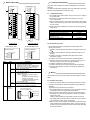
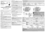
3. Name of Each Part
4. Loading and Installation
A1S62TCRT-S2
1)
CH1
CH2
RUN
H OUT
C OUT
ALM
H OUT
C OUT
ALM
CH1
1)
CH2
1
L1H
L2H
L1C
3
L2H
5
L2C
;
A1
4
6
NC
NC
7
B1
B1
8
NC
NC
9
b1
b1
10
NC
NC
11
NC
NC
12
NC
NC
13
NC
NC
14
NC
NC
15
A2
A2
16
NC
NC
17
B2
B2
18
NC
NC
19
b2
H OUT
C OUT
ALM
BR.W
H OUT
C OUT
ALM
BR.W
RUN
1
L1H
2
L1C
L2C
+ A1
Precautions when handling the A1S62TC and installation environment are
explained.
For details of implementing and setting up this unit, please refer to the User’s
Manual for the programmable controller CPU used.
A1S62TCRTBW-S2
b2
20
2
3
4
5
6
7
8
9
10
11
12
13
14
15
16
17
18
19
20
4.1 Handling Instructions
1) The module case is made of plastic. Be sure not to drop it or subject it
to strong vibration.
2) Do not remove the module printed circuit boards from the case.
It may cause trouble.
3) When connecting the wiring, do not allow wire cuttings or other foreign
matter to enter from the top of the module. Remove any foreign matter
from the module.
4) Tighten the module installation screws within the following tightening
torque range.
Screw position
Module installation screw (M4 screw)
Terminal block terminal screw (M3.5 screw)
Terminal block installation screw (M4 screw)
Wire breakage detection connector installation
screw (M2.6 screws)*
Cable fixing screw (M2 screws)*
Tightening torque range
78 to 118N•cm
59 to 88N•
78 to 118N•cm
15 to 30N•cm
11 to 14N•cm
*:Use only for A1S62TCRTBW-S2 .
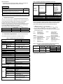
2)
A1S62TCRT-S2
A1S62TCRTBW-S2
A1S62TCRT-S2 LED
A1S62TCRTBW-S2 LED
A1S62TCRT-S2
A1S62TCRTBW-S2
CH1
CH2
Number
1)
H OUT
C OUT
ALM
H OUT
C OUT
ALM
RUN
CH2
Name
LED
RUN
OUT
ALM
BR.W
2)
CH1
Wire breakage
detection
connector
RUN
H OUT
C OUT
ALM
BR.W
H OUT
C OUT
ALM
BR.W
Description
A1S62TC operation status display
ON: Normal operation in progress
Flashing (2 sec. ON/2 sec. OFF): Write data error
Flashing (1 sec. ON/1 sec. OFF): Hardware error
OFF: 5V power shutoff, Watchdog timer error
Transistor output status display
ON: Transistor output ON
OFF: Transistor output OFF
Alert alarm status display
ON: Alert alarm is ON.
Flashing: The measured temperature range is
exceeded.
The platinum temperature-measuring
resistor is not connected.
The platinum temperature-measuring
resistor cable is disconnected.
OFF: Alert alarm is OFF
Heater wire breakage detection status display
ON: Heater wire breakage is detected.
OFF: Heater wire breakage is not detected.
Connector for current sensor
Wire breakage detection
connector installation screw
BW1(For CH1)
BW2(For CH2)
Cable fixing screw
NC(Unusable)
4.2 Installations Enviroment
Never install the AnS series programmable controller system in the
following environments:
1) Locations where the ambient temperature is outside the range of 0 to
55 .
2) Locations where the ambient humidity is outside the range of 10 to
90%RH.
3) Locations where dew condensation takes place due to sudden
temperature changes.
4) Locations where there are corrosive and/or combustible gasses.
5) Locations where there is a high level of conductive power (such as
dust and iron filings, oil mist, salt, and organic solvents).
6) Locations exposed to the direct rays of the sun.
7) Locations where strong power and magnetic fields are generated.
8) Locations where vibration and shock are directly transmitted to the
main module.
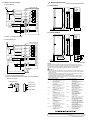
5. Wiring
The precaution when wiring and the module connection example are shown
below.
5.1 Precaution when wiring
In order to have the best result from the A1S62TC functions and to make
the system highly reliable, an external cabling with low noise effects are
necessary.
The external wiring precautions are shown below:
1) Use separate cables for the alternating current and A1S62TC external
input signals to avoid A/C surges and induction effects.
2) Do not bunch the cables with the main circuit, high-voltage cable or
load cables from other than programmable controller, or install them
close to each other.
Install the cables far apart from high-frequency circuits, such as the
high-voltage cable and inverter load main circuit, as much as possible.
This increases the noises, surges, and induction.
3) Perform a one-point grounding for the shielded line and shields of the
seal and cable at the programmable controller. However, there may
be cases when grounding should be performed externally depending
on the noise condition.