1
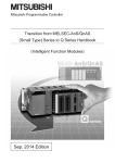
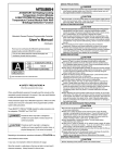
[Wiring Precautions] Mitsubishi General-Purpose Programmable Controller Renewal Tool Conversion Adapter Model ERNT-ASQT62TCRT ERNT-ASQT62TCRTBW 2.Product Specifications CAUTION Carry out wiring for the Conversion Adapter correctly after checking the specification and terminal arrangement for the module used. Connecting a power supply with a different voltage rating or incorrect wiring may cause a fire or failure. Tighten the MELSEC-AnS Series terminal installation screws and terminal screw securely by applying torque within the specified limits. Loose screws will cause short circuit, fire or malfunction. Excessive tightening will damage the screws or the Conversion Adapter which in turn will cause dropping of parts, short circuit or malfunction. Use care to prevent foreign materials including cuttings and wiring debris from entering the Conversion Adapter or the MELSEC-Q Series Module. These will be cause for fire, failure or malfunction. [Startup and Maintenance Precautions] 50CM-D180155-A(1307) Do not touch live terminals. There is a danger of electric shock or malfunction. Shut off the external power supply for the system in all phases before cleaning or retightening the terminal screws. Failure to do so may result in electric shock or cause the MELSEC-Q Series module to fail or malfunction. Loose screws can lead to dropping, shorting, and malfunction. Excessive tightness of the screws can lead to breakage of the screws, Conversion Adapter, Mounting Bracket, or MELSEC-Q Series Module, possibly causing the dropping, shorting, and malfunction thereof. HEAD OFFICE:Hulic KUDAN BLDG.1-13-5,KUDANKITA CHIYODA-KU,TOKYO 102-0073,JAPAN NAGOYA ENGINEERING OFFICE:139 SHIMOYASHIKICHO-SHIMOYASHIKI,KASUGAI,AICHI 486-0906,JAPAN SAFETY PRECAUTIONS CAUTION (Always read these precautions prior to use.) Before using this product, please read this manual carefully and pay full attention to safety to ensure that the product is used correctly. The precautions presented in this manual are concerned with this product only. For Programmable Controller system safety precautions, refer to the user’s manual of the MELSEC-Q series CPU module to be used. In this manual, the safety precautions are ranked as “WARNING” and “CAUTION.” Indicates that incorrect handling may cause hazardous conditions, resulting in death or severe injury. Indicates that incorrect handling may cause hazardous conditions, resulting in medium or minor injury and/or property damage. Note that failure to observe the CAUTION level instructions may lead to a serious consequence according to the circumstances. Always follow the precautions of both levels because they are important to personal safety. Please keep this manual in an easy-to-access location for future reference, and be sure to provide the manual to the end user. Do not modify the Conversion Adapter or take it apart. Doing so will cause failure, malfunction, personal injury, or fire. Do not drop the Conversion Adapter and Mounting Bracket or do not give a strong impact to it. This will cause damage. CAUTION When making a switch from the MELSEC-AnS Series to the MELSEC-Q Series, be sure to consult user's manual supplied with individual module under the MELSEC-Q Series to confirm differences in various aspects including performance, function, CPU input/output signals and buffer memory addresses between the two series. [Installation Precautions] CAUTION Use the Conversion Adapter in the environmental conditions that are specified in the general specification contained in the user's manual supplied with the MELSEC-Q Series CPU Module. If the Products are used in any environment beyond the bounds of the general specification, electric shock, fire, malfunction, or damage to or degradation of the Products will result. Do not directly touch any conductive parts of Conversion Adapter. Contact will cause malfunction or failure in the system. Fasten the Conversion Adapter and the Mounting Bracket securely with retaining screws, and tighten the screws by applying torque within specified limits. Loose screws can lead to the dropping of the Conversion Adapter or Mounting Bracket, possibly causing breakage thereof. Excessive tightness of the screws can lead to breakage of the screws, Conversion Adapter, Mounting Bracket, or MELSEC-Q Series Module, possibly causing the dropping, shorting, and malfunction thereof. Always check for correct match between MELSEC-Q Series and the Conversion Adapter. Incorrect match can cause damage to the MELSEC-Q Series Module. When installing the Conversion Adapter, take care not to get your hand snagged on the Mounting Bracket or the like. Injury may result. When installing or removing the MELSEC-Q Series Module complete with a Converter Adapter, be sure to hold it with both hands. Dropping may lead to breakage. 2 channels Q64TCRTN (Heating-cooling control) Possible 70 2 channels Q64TCRTBWN (Heating-cooling control) Impossible (*3) 160 1) A1S62TCRT-S2, A1S62TCRTBW-S2 A1S62TCRT-S2 A1S62TCRTBW-S2 Terminal block TB2 TB4 TB6 TB8 TB10 TB12 TB14 TB16 TB18 TB20 TB1 TB3 TB5 TB7 TB9 TB11 TB13 TB15 TB17 TB19 *1 [Disposal Precautions] CAUTION 2) A1S64TCTRT, A1S64TCTRTBW Internal circuit diagram of ERNT-ASQT62TCRT Terminal No. TB1 TB2 TB3 TB4 TB5 TB6 TB7 TB8 TB9 TB10 TB11 TB12 TB13 TB14 TB15 TB16 TB17 TB18 TB19 TB20 Terminal No. TB1 TB2 TB3 TB4 TB5 TB6 TB7 TB8 TB9 TB10 TB11 TB12 TB13 TB14 TB15 TB16 TB17 TB18 Signal Name L1H L1C L2H L2C COMCH1A NC CH1B NC CH1b NC NC NC NC NC CH2A NC CH2B NC CH2b Internal circuit diagram of ERNT-ASQT62TCRT Q64TCRTN Signal Name Terminal block L1H Q64TCRTBWN L1C (Right slot side) L2H Terminal block L2C COMTB1 TB2 NC TB3 TB4 CH1 A TB5 TB6 CH2 A TB7 TB8 CH1 B TB9 TB10 CH2 B TB11 TB12 CH1 b TB13 TB14 CH2 b TB15 TB16 MT3 A TB17 TB18 MT4 A MT3 B MT4 B MT3 b MT4 b Terminal No. TB1 A1S64TCTRT TB2 TB3 A1S64TCTRTBW TB4 (Heating-cooling control) TB5 Terminal block TB6 TB1 TB2 TB7 TB3 TB4 TB8 TB5 TB6 TB9 TB7 TB8 TB10 TB9 TB10 TB11 TB11 TB12 TB12 TB13 TB14 TB13 TB15 TB16 TB14 TB17 TB18 TB15 TB19 TB20 TB16 TB17 TB18 TB19 TB20 *2 《Disconnection detector connector conversion cable》 When disposing of the product, treat it as industrial waste. A1S62TCRTBW-S2 A1S64TCTRTBW (Heating-cooling control) Disconnection detector connector 1 2 3 4 5 6 7 8 EMC AND LOW VOLTAGE DIRECTIVES Compliance to the EMC Directive, which is one of the EU Directives, has been a legal obligation for the products sold in European countries since 1996 as well as the Low Voltage Directive since 1997. Manufacturers who recognize their products are compliant to the EMC and Low Voltage Directives are required to declare that print a "CE mark" on their products. Terminal Signal No. Name TB1 NC TB2 CT1 TB3 CT1 TB4 CT2 TB5 CT2 TB6 CT3 TB7 CT3 TB8 CT4 TB9 CT4 TB10 CT5 TB11 CT5 TB12 CT6 TB13 CT6 TB14 CT7 TB15 CT7 TB16 CT8 TB17 CT8 TB18 NC Terminal Signal No. Name 1 BW1 2 BW1 3 BW2 4 BW2 5 NC 6 NC 7 NC 8 NC Authorized representative in Europe is shown below. Name: Mitsubishi Electric Europe BV Address: Gothaer Strasse 8, 40880 Ratingen, Germany Terminal No. TB1 TB2 TB3 TB4 TB5 TB6 TB7 TB8 TB9 TB10 TB11 TB12 TB13 TB14 TB15 TB16 TB17 TB18 Signal Name L1H L1C L2H L2C COMCH1A MT1A CH1B MT1B CH1b MT1b NC NC NC MT2A CH2A MT2B CH2B MT2b CH2b Signal Name L1H L1C L2H L2C COMNC CH1 A CH2 A CH1 B CH2 B CH1 b CH2 b MT3 A MT4 A MT3 B MT4 B MT3 b MT4 b Q64TCRTN Terminal block Q64TCRTBWN (Right slot side) Terminal block TB2 TB4 TB6 TB8 TB10 TB12 TB14 TB16 TB18 *2 TB1 TB3 TB5 TB7 TB9 TB11 TB13 TB15 TB17 Precaution for wiring Q64TCRTBWN (Left slot side) Terminal block TB2 TB4 TB6 TB8 TB10 TB12 TB14 TB16 TB18 *1 Always leave the MELSEC-AnS series module terminals (TB9, TB11, TB17 and TB19) open (unconnected). (They are connected to the MELSEC-Q series module inside the conversion adapter.) *2 When using ERNT-ASQT62TCRTBWN, always install the disconnection detector connector conversion cable to the left side, and the conversion adapter to the right side. Installing them the other way around may cause failure of the MELSEC-Q series module. *2 TB1 TB3 TB5 TB7 TB9 TB11 TB13 TB15 TB17 (Left side) Disconnection detector connector conversion cable Q64TCRTBWN (Right side) Conversion adapter <Specification comparison> 1.Overview Model Specification This manual describes specifications, handling and other information about the Conversion Adapter “ERNT-ASQT62TCRT, ERNT-ASQT62TCRTBW” available as Renewal Tools for the Mitsubishi General-Purpose Programmable Controller. The Conversion Adapter is a product for effecting conversion to transcend difference in pin assignment between the MELSEC-AnS Series and the MELSEC-Q Series. Before attempting to make a switch from MELSEC-AnS Series to MELSEC-Q Series in your installation, consult the user's manual supplied with individual module under the latter series to learn about how they differ in various aspects including performance and function. Once you have opened the packaging, verify that it contains the following products. Quantity Product Conversion Adapter (ERNT-ASQT62TCRT) Mounting bracket Mounting bracket fixing screw (M3.5×6) Terminal block cover Disconnection detector connector conversion cable Disconnection detector connector conversion cable installation screw (M3×8) This manual ERNT-ASQT62 TCRT 1 1 2 1 - ERNT-ASQT62 TCRTBW (*1) 1 1 2 1 1 - 2 1 1 *1:ERNT-ASQT62TCRTBW is a model (product) name of a set of ERNT-ASQT62TCRT conversion adapter and the disconnection detector connector conversion cable. Control output Number of temperature input points Supported thermocouples Indication accuracy MELSEC-AnS Series MELSEC-Q Series A1S64TCTRT A1S64TCTRTBW Q64TCRTN Q64TCRTBWN A1S62TCRTBW-S2 (Heating-cooling control) (Heating-cooling control) (Heating-cooling control) (Heating-cooling control) Transistor output 2 channels/module Refer to the table on the back Full-scale×(±0.3%)±1digit − − − Full-scale×(±0.3%)±1digit Full-scale×(±0.3%) Full-scale×(±0.7%)±1digit Full-scale×(±0.7%) 500ms/2 channels (constant independently of the number of channels used) 1 to 100s A1S62TCRT-S2 Ambient temperature 23℃±5℃ Ambient temperature 25℃±5℃ Ambient temperature 0 to 55℃ Sampling cycle Heating control output cycle Cooling control output cycle Effect from wiring resistance of 1Ω Sensor current Allowable input wire resistor effects Input impedance Input filter Sensor correction value setting Operation at sensor input disconnection Operation at sensor input short-circuited Temperature control method PID constants setting Proportional band (P) Heating proportional band (Ph) PID constants range Cooling proportional band (Pc) Integral time (I) Derivative time (D) Set value setting range Cooling method setting Output signal Rated load voltage Max. load current Transistor output Max. inrush current Leakage current at OFF Max. voltage drop at ON Response time WARNING Before attempting to install the Unit or carry out the necessary wiring, make certain that the external power supply, used in the system, is shut off on all three phases. Failure to do so may result in electric shock or damage to the product. Heater disconnection detection specifications After installation and wiring, close the terminal block cover before turning on the module for operation. Failure to do so may result in electric shock. I/O occupied points Connection method Internal current consumption (5VDC) Refer to the table on the back Approx. 0.3mA 10Ω or less Approx. 0.25mA 20Ω or less − − 1MΩ − 0 to 100s (0:Input filter OFF) -50.00 to 50.00% Upscale processing Downscale processing − − PID ON/OFF pulse or two-position control PID ON/OFF pulse Can be set by auto tuning 0.1 to 1000.0% − 0.1 to 1000.0% 0.0 to 1000.0% (0:Two-position control) − 1 to 3600s 0 to 3600s (0:P control and PD control) 0 to 3600s (0:PI control) 0 to 3600s (0:P control and PD control) Within the temperature range set by the temperature sensor to be used Air cooling/water cooling Air cooling/water cooling/Linear ON/OFF pulse 10.2 to 30VDC 10 to 30VDC 0.1A/point, 0.4A/common 0.4A 10ms 0.1mA or less 1.0VDC(TYP)at 0.1A 2.5VDC(MAX) at 0.1A OFF→ON:2ms or less ON→OFF:2ms or less Between input and grounding: Transformer insulation Between input and channel: Transformer insulation [Wiring Precautions] Weight (g) 《Conversion adapter》 Insulation method Use of the MELSEC-Q series large type base unit (AnS series size) A1S64TCTRTBW(Heating-cooling control) Authorized representative in Europe [Precautions before using] After replacement MELSEC-Q Series Model A1S62TCRT-S2 A1S64TCTRT(Heating-cooling control) A1S62TCRTBW-S2 ERNT-ASQT62TCRT *1 No. of channels *2:It is necessary to fix the disconnection detector connector conversion cable that comes with the product using the separately-sold "base adapter (for panel surface installation)" or "conversion adapter DIN rail mounting bracket (for DIN rail installation)". Refer to "4.3 ERNT-ASQT62TCRTBW Installation Procedure". *3:The MELSEC-Q series module cannot be installed to the MELSEC-Q series large type base unit (AnS series size). WARNING CAUTION Before replacement MELSEC-AnS Series Model Model ERNT-ASQT62TCRTBW (*2) User’s Manual WARNING For detail specification and general specification which do not appear in the specification comparison charts contained herein, see the user's manual supplied with the MELSEC-Q Series module you use. Those parts of the specification that differ between the MELSEC-AnS Series and the MELSEC-Q Series are where a switch from the first series to the second is subjected to specification-related restrictions. Check the specification of the devices to be connected for more details. Furthermore, it is recommended to refer to the “Transition from MELSEC-AnS/QnAS (Small Type) Series to Q Series Handbook (Intelligent Function Modules): L (NA)-08220ENG” issued by Mitsubishi Electric. The Q64TCRTBWN module cannot be installed to the MELSEC-Q series large type base unit (AnS series size). For replacement using the ERNT-ASQT62TCRTBW conversion adapter, install the Q64TCRTBWN module to the QB type base unit. U.R.D.co.,LTD. CTL-12-S36-8 (0.0 to 100.0A) CTL-6-P(-H) (0.00 to 20.00A) Current sensor − Input method Input accuracy Alarm delay count − − − Multiplexor method A/D conversion 20-point terminal block 0.19A 20-point terminal block and 8-point connector 0.28A − 3 to 255 Between input terminal and programmable controller power supply:Transformer insulation Between input channels:Transformer insulation − − − − 32 points 20-point terminal block 0.33A − U.R.D.co.,LTD. CTL-12-S36-8 (0.0 to 100.0A) CTL-12-S36-10 (0.0 to 100.0A) CTL-12-S56-10 (0.0 to 100.0A) CTL-6-P(-H) (0.00 to 20.00A) − − − Full scale×(±1.0%) 3 to 255 20-point terminal block and 8-point connector 0.39A 16 points 18-point terminal block 0.29A U.R.D.co.,LTD. CTL-12-S36-8 (0.0 to 100.0A) CTL-6-P(-H) (0.00 to20.00A) Multiplexor method A/D conversion Full scale×(±1.0%) − 3 to 255 32 points Two 18-point terminal blocks 0.33A Precautions for the program (1) AnS series module and Q series module differ from each other in the way input/output signals (X, Y) and buffer memory addresses are allocated. Therefore, you need make necessary changes to the sequence program that is used. Point (1) When the measured temperature has a margin of error, the sensor compensation function of Q64TCRTN/Q64TCRTBWN can compensate the error. 4.3 ERNT-ASQT62TCRTBW Installation Procedure ℃ Platinum temperature-measuring resistor type ゜F Temperature measurement range Resolution Pt100 -200.0 to 600.0 -200.0 to 200.0 0.1 JPt100 -200.0 to 500.0 -200.0 to 200.0 0.1 Base Adapter To the control panel Temperature measurement range Resolution -300 to 1100 1 -300.0 to 300.0 0.1 MELSEC-Q Sereis module MELSEC-Q Series base unit -300 to 900 1 -300.0 to 300.0 0.1 2 MELSEC-AnS Series terminal block 4 (1) Before attempting to install the Unit or carry out the necessary wiring, make certain that the external power supply, used in the system, is shut off on all three phases. Failure to do so may result in electric shock or damage to the product. (2) Do not touch live terminals. There is a danger of electric shock or malfunction. (3) Do not modify the Conversion Adapter or take it apart. Doing so will cause failure, malfunction, personal injury, or fire. (4) Do not touch the energized part of the Conversion Adaptor directly. Contact will cause malfunction or failure in the system. (5) Fasten the Conversion Adapter and the Mounting Bracket securely with retaining screws, and tighten the screws by applying torque within specified limits. Loose screws can lead to the dropping of the Conversion Adapter or Mounting Bracket, possibly causing breakage thereof. Excessive tightness of the screws can lead to breakage of the screws, Converter Adapter, Mounting bracket, or MELSEC-Q Series Module, possibly causing the dropping, shorting, and malfunction thereof. (6) Use care to prevent foreign materials including cuttings and wiring debris from entering the Conversion Adapter or the MELSEC-Q Series Module. These will be cause for fire, failure or malfunction. (7) Do not drop the Conversion Adapter and Mounting Bracket or do not give a strong impact to it. This will cause damage. 3 It is necessary to fix the hook of the mounting bracket into the front part (bottom part) of MELSEC-Q series module. Install the mounting bracket before installing the MELSEC-Q series module to the base unit. 1) Tilt the mounting bracket to the left, and fix the hook of the mounting bracket into the serial number indicated area of the front part (bottom part) of MELSEC-Q series module. 2) With the hook engaged, straighten the mounting bracket to cover the front part of MELSEC-Q series module. 3) Closely fix the mounting bracket to the MELSEC-Q series module. 4) Align the screw holes and fix the mounting bracket using the mounting bracket fixing screws. (Refer to 4.5 for the tightening torque.) Condition after the installation is completed Conversion adapter (Right side) Conversion adapter Connector bracket <MELSEC-Q Series> 6 110mm Hook 4 1 MELSEC-Q Series base unit 27.4 【Installation with the Base Adapter】 Secured using screws Base Adapter To the control panel Precaution 110mm 1.9mmUP 47.5mmUP Conversion adapter Disconnection detector connector conversion cable Base adapter 157.5mm MELSEC-AnS Series terminal block A1S62TCRT-S2 A1S64TCTRT 106mm 5 The separately-sold Conversion Adapter DIN rail Mounting Bracket (ERNT-ASQDIN) is required to use the Conversion Adapter with a fixture on this Base Unit. Refer to the user's manual of the Conversion Adapter DIN rail mounting bracket for the installation method. <Conversion Adapters> ・ERNT-ASQT68AD-G ・ERNT-ASQTD62D ・ERNT-ASQT68TD-H01 ・ERNT-ASQT64TCTTBW ・ERNT-ASQT68TD-H02 ・ERNT-ASQT64TCRTBW ・ERNT-ASQTD61 ・ERNT-ASQT62TCTTBW ・ERNT-ASQTD62 ・ERNT-ASQT62TCRTBW 4.2 ERNTASQT62 TCRT Installation Procedure 4.3 ERNTASQT62 TCRTBW Installation Procedure Remove the terminal block attached with the MELSEC-Q Series module after loosening the terminal block installation screws (2 places up and down). (When using Q64TCRTBWN, remove the terminal blocks from both right and left slots.) The MELSEC-Q series terminal block is not used. 1 1 69mm 4mmUP 70.9mm 65mm 5.9mmUP Conversion adapter Disconnection detector connector conversion cable 2 2 Precaution 3 3 The terminal block cover for MELSEC-AnS Series is bigger than the width of the MELSEC-Q Series Module. Therefore, it is necessary to replace it with the terminal block cover supplied with the converter adapter. Before tightening the installation screws, check that the Conversion Adapter has been securely installed on the MELSEC-Q Series module. Tightening the screws in floating-off state or tilting state will damage the Conversion Adapter installation screws and the mounting bracket. <MELSEC-Q Series> Terminal block cover for the MELSEC-AnS Series Replace the terminal block cover with the one supplied with the Conversion Adapter. 27.4mm 3.3 Installation Environment The installation environment is the same as MELSEC-Q series CPU Module to use. Refer to the user's manual of the MELSEC-Q Series CPU Module to be used. Gratis Warranty Terms and Gratis Warranty Range Gratis Warranty Period The gratis warranty period of this product shall be one (1) year from the date of purchase or delivery to the designated place. Note that after manufacture and shipment from MEE, the maximum distribution period shall be six (6) months, and the gratis warranty period after manufacturing shall be limited to eighteen (18) months. In addition, the gratis warranty period for repaired products shall not exceed the gratis warranty period established prior to repair. Gratis Warranty Range The gratis warranty range shall be limited to normal use based on the usage conditions, methods and environment, etc., defined by the terms and precautions, etc., given in the instruction manual, user’s manual and caution labels on the product. Warranty Period after Discontinuation of Production 44.5mmUP <MELSEC-AnS Series> Install the MELSEC-Q Series module to the MELSEC-Q Series Base Unit. Install the Conversion Adapter to the mounting bracket, and secure it using the Conversion Adapter installation screws (M3 × 25). (2 places) Conversion adapter DIN rail mounting bracket 150.5mm 106mm 34.5mm MELSEC-Q Series terminal block installation screw (Secure it in two places, top and bottom.) Refer to "4.1 Mounting Bracket Installation Method". Q64TCRTBWN Product Warranty Details Please confirm the following product warranty details prior to product use. If any fault or defect (hereinafter referred to as “Failure”) attributable to Mitsubishi Electric Engineering Company Limited (hereinafter referred to as “MEE”) should occur within the gratis warranty period, MEE shall repair the product free of charge via the distributor from whom you made your purchase. Secure the mounting bracket to the MELSEC-Q Series module (to the right slot when using Q64TCRTBWN) using the mounting bracket fixing screws (M3.5 × 6). (2 places) 150.5mm 44.5mmUP 4mm Description Conversion adapter A1S62TCRTBW-S2 A1S64TCTRTBW A1S62TCRTBW-S2 A1S64TCTRTBW ↓ Q64TCRTBWN Installation with the DIN rail Mount the DIN rail mounting adapter manufactured by Mitsubishi Electric to the MELSEC-Q Series Base Unit. For how to install the adapter to the MELSEC-Q Series Base Unit, refer to the QCPU User’s Manual. MELSEC-AnS Series terminal block installation screw (M4) MELSEC-AnS Series terminal block cover 2 Installation with the Base Adapter Mount the MELSEC-Q Series Base Unit to the Base Adapter. Refer to the Base Adapter's manual for how to install them to the control panel. Q64TCRTN 65mm 4mm DIN rail MELSEC-Q Series base unit Unit:mm 4.4 Installation Method MELSEC-Q Sereis module Mounting bracket 【Installation with the DIN rail】 Mounting portion A(Zoom) The separately-sold Conversion adapter DIN rail mounting bracket (ERNT-ASQDIN□□) is required to use this ERNT-ASQT62TCRTBW install with the DIN rail. Refer to the user's manual of the DIN rail mounting bracket of the Conversion Adapter for the installation method. MELSEC-Q Series module Installation with the DIN rail Because the module is increased in depth and height dimension, check dimensional data before installing the module. A1S62TCRT-S2 A1S64TCTRT ↓ Q64TCRTN Conversion adapter installation screw M3×25 4 47.5mmUP Q64TCRTBWN Mounting portion A Conversion adapter DIN rail mounting bracket(bottom) Mounting bracket fixing screw M3.5×6 Conversion adapter A1S62TCRTBW-S2 A1S64TCTRTBW 7 4.2 ERNT-ASQT62TCRT Installation Procedure Q64TCRTN A1S62TCRTBW-S2 A1S64TCTRTBW ↓ Q64TCRTBWN 5 Disconnection detector connector conversion cable 1 2 3 4 5 6 7 8 9 10 11 12 13 14 15 16 17 18 Mounting bracket fixing screw (M3.5×6) 3 157.5mm 3 DIN rail 27.4mm Base adapter Disconnection detector connector conversion cable (ERNT-ASQT62TCRTBW only) 1 【Installation with the DIN rail】 MELSEC-Q Series base unit Conversion adapter Terminal block cover MELSEC-AnS Series disconnection detector connector 2 Serial No. Installation with the Base Adapter Because the module is increased in depth and height dimension, check dimensional data before installing the module. A1S62TCRT-S2 A1S64TCTRT Mounting bracket Disconnection detector connector conversion cable installation screw M3×8 4 1 A1S62TCRT-S2 A1S64TCTRT ↓ Q64TCRTN Conversion adapter MELSEC-Q Series terminal block installation screw (M3.5) 3 2 34.5mm 5.External Dimensions MELSEC-AnS Series terminal block cover (Left side) Disconnection detector connector conversion cable 5 MELSEC-Q series module MELSEC-AnS Series terminal block installation screw (M4) 2 Use Precautions Because the module is reduced in width dimension (34.5mm→27.4mm) and thus in area available for wiring, check dimensional data before installing the module. <MELSEC-AnS Series> Terminal block cover 8 (Terminal block) 3.2 Use Precautions Depth and Height dimension 7 Mounting portion A 4.1 Mounting Bracket Installation Method Mounting bracket Item Width dimension of module 1 Tighten the module installation screws to the specified torque below. An inappropriate tightening torque could cause the product to fall or result in a short circuit, product failure or malfunction. Screw Location Tightening Torque Range Mounting bracket fixing screw (M3.5×6) 0.68 to 0.92N・m Conversion Adapter installation screw (M3×25) 0.43 to 0.57N・m MELSEC-AnS Series terminal block installation screw (M4 screw) 0.78 to 1.18N・m MELSEC-AnS Series terminal block terminal screw (M3.5 screw) 0.59 to 0.88N・m MELSEC-Q Series terminal block installation screw (M3.5 screw) 0.66 to 0.89N・m Disconnection detector connector conversion cable installation screw 0.61 to 0.82N・m (M3×8) 31.5 3.1 Handling Precautions Mounting bracket fixing screw M3.5×6 Conversion adapter installation screw Precaution M3×25 Mounting bracket 4.Part Names and Installation Method 3.Mounting and Installation 4.5 Tightening Torque 【Installation with the Base Adapter】 102 < Specification comparison (continued) > Supported platinum temperature-measuring resistor − 4 − 5 − 6 4 7 5 8 Fix the terminal block for the disconnection detector connector conversion cable to the target MELSEC-Q series module (left slot) using the MELSEC-Q series terminal block installation screws (M3.5) (2 places, top and bottom). Fix the connector bracket of the disconnection detector connector conversion cable to the base adapter or the conversion adapter DIN rail mounting bracket (bottom) using the disconnection detector connector conversion cable installation screws (M3 × 8) (2 places). Connect the MELSEC-AnS series disconnection detector connector to the disconnection detector connector conversion cable. Secure the MELSEC-AnS Series terminal block to the Conversion Adapter with the supplied terminal block installation screw (M4). (2 places, top and bottom.) Remove the terminal block cover from the MELSEC-AnS Series terminal block and fit the terminal block cover supplied with the Conversion Adaptor in place. (1) MEE shall offer product repair services (fee applied) for seven (7) years after production of the product has been discontinued. Discontinuation of production shall be reported via distributors. (2) Product supply (including spare parts) is not possible after production has been discontinued. Exclusion of Opportunity Loss and Secondary Loss from Warranty Liability Regardless of the gratis warranty period, MEE shall not be liable for compensation for damages arising from causes not attributable to MEE, opportunity losses or lost profits incurred by the user due to Failures of MEE products, damages or secondary damages arising from special circumstances, whether foreseen or unforeseen by MEE, compensation for accidents, compensation for damages to products other than MEE products, or compensation for other work carried out by the user. Changes in Product Specifications The specifications given in the catalogs, manuals and technical documents are subject to change without notice. This document is a new publication, effective July 2013. Specifications are subject to change without notice. The standard price does not include consumption tax. Please note that consumption tax will be added at the time of purchase. This manual was printed on recycled paper. Developed July 2013 50CM-D180155-A