1
version 3.5
ArcPower 36
Table of contents
1. Safety instructions.......................................................................................................... 3
2. Operating determinations............................................................................................... 3
3.Description of the ArcPower 36...................................................................................... 4
4.Installation........................................................................................................................ 4
4.1.Connection to the mains............................................................................................. 4
4.2.Mounting the ArcPower 36.......................................................................................... 5
4.3.Conection cables......................................................................................................... 5
5.Installing instructions...................................................................................................... 6
5.1.DMX operating............................................................................................................ 6
5.2.Master-slave operating................................................................................................ 8
5.3.Operating via Dynet protocol....................................................................................... 9
6.ArcPower 36 - Control menu map................................................................................. 11
7.ArcPower 36-DMX protocol .......................................................................................... 12
8.Control board.................................................................................................................. 13
8.1 Addressing the ArcPower 36 . .................................................................................. 13
8.2 Program running....................................................................................................... 13
8.3 Manual mode............................................................................................................ 14
8.4 Test sequences......................................................................................................... 15
8.5 Stand-alone mode..................................................................................................... 15
8.6 Special functions....................................................................................................... 15
9.Control of the ArcPower 36 via RS-232........................................................................ 17
9.1Wiring an RS-232 serial port ..................................................................................... 17
9.2 Selecting a zone........................................................................................................ 17
9.3 Setting a serial port of PC......................................................................................... 17
9.4 Zone commands....................................................................................................... 17
10.Technical Specifications:............................................................................................ 19
11 Replacing the fuse ...................................................................................................... 20
CAUTION!
Unplug mains lead before opening the housing!
FOR YOUR OWN SAFETY, PLEASE READ THIS USER MANUAL CAREFULLY
BEFORE YOU INITIAL START - UP!
1. Safety instructions
Every person involved with installation and maintenance of this product has to:
- be qualilfied
- follow the instructions of this manual
CAUTION!
Be careful with your operations. With a high voltage you can suffer
a dangerous electric shock when touching the wires inside the unit!
This product has left our premises in absolutely perfect condition. In order to maintain this condition and to
ensure a safe operation, it is absolutely necessary for the user to follow the safety instructions and warning
notes written in this manual.
To prevent from danger of accident ,the device has to be fixed on flat, non-flammable surface in compliance with the installing instruction included in this manual.
Important:
The manufacturer will not accept liability for any resulting damages caused by the non-observance of this
manual or any unauthorized modification to the product.
Always ground the unit.
The electric connection, repairs and servicing must be carried out by a qualified employee.
Do not connect this unit to a dimmer pack.
Use a source of AC power that complies with local building and electrical rules.AC power has to have both
overload and short circuit protection
2. Operating determinations
This product was designed for indoor use only.
If the unit has been exposed to drastic temperature fluctuation (e.g. after transportation), do not switch it on
immediately. The arising condensation water might damage your unit. Leave the unit switched off until it has
reached room temperature.
Avoid brute force when installing or operating the unit.
When choosing the installation-spot, please make sure that the unit is not exposed to extreme heat, moisture
or dust.
Only operate the unit after having checked that the housing is firmly closed and all screws are tightly fastened.
The maximum ambient temperature 40° C must never be exceeded.
Operate the unit only after having familiarized with its functions. Do not permit operation by persons not qualified for operating the unit. Most damages are the result of unprofessional operation!
Please use the original packaging if the product is to be transported.
Please consider that unauthorized modifications on the unit are forbidden due to safety reasons!
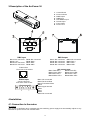
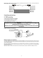
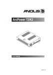
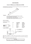
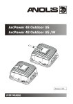
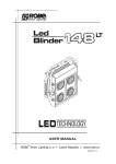
3.Description of the ArcPower 36
1 - Control Board
2 - Power Indicator
3 - DMX Output
4 - DMX Input
5 - LED Module Input
6 - RS 232 Input
7 - Fuse Holder
8 - Power Cord
DMX Input
Pin 1: Not connected
Pin 2: +12V
Pin 3: Not connected
Pin 4: Not connected
DMX Output
Pin 1: Not connected
Pin 2: Not connected
Pin 3: Not connected
Pin 4: Not connected
Pin 5: Not connected
Pin 6: Data +
Pin 7: Data Pin 8: GND
Pin 5: Not connected
Pin 6: Data +
Pin 7: Data Pin 8: GND
RJ45 socket LED module Input
Front view of the socket:
Pin 1: Red LED +
Pin 5: Red LED Pin 2: Green LED +
Pin 6: Green LED Pin 3: Blue LED +
Pin 7: Blue LED Pin 4: White LED +
Pin 8: White LED -
RS232 Input
Canon 9-pin male
Front view of the socket:
Pin 1: Not connected
Pin 2: Received Data
Pin 3: Transmitted Data
Pin 4:
Pin 5: Signal Ground
Pin 6:
Pin 7:
Pin 8:
Pin 9: Not connected
4.Installation
4.1.Connection to the mains
CE version:
This version of ArcPower 36 is equipped with auto-switching power supply that automatically adjusts to any
50/60Hz AC power source from 100-240 Volts.
Carefully prepare the end of the the supply cord and fit a suitable plug.A 3-prong grounding-type plug must be
installed following the manufacturer´s instructions.The earth has to be connected!
Cord plug connections:
Cable Pin
International
Brown
Live Light blue
Neutral
Yellow/Green
Earth
L
N
ETL version:
This version of ArcPower 36 is equipped with auto-switching power supply that automatically adjusts to any
50/60Hz AC power source from 100-120 Volts.
Connect the ArcPower 36 directly to AC power with the supply cord.
This device falls under protection class I.Therefore the ArcPower 36 has to be connected to a mains socket outlet with a protective earthing connection.
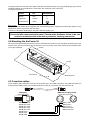
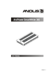
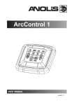
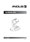
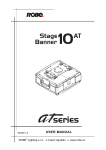
4.2.Mounting the ArcPower 36
The ArcPower 36 should be be placed on a non-f lammable f lat surface in any orientation and fixed by the two
screws.There are two mounting holes of diameter 5 mm in housing of the driver. Ensure that instalation place
Screw
is enough ventilated.
Screw
Flat surface
Mounting hole
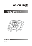
4.3.Conection cables
1.The adapter cable RJ45/XLR connects the ArcPower 36 to the DMX controller.If your DMX controller has
RJ45 socket for DMX output,use standard RJ45 patch cable for connection with the ArcPower 36.
RJ45 plug
View facing pins
DMX 512 XLR plug (male)
Front view of the plug
Pin 1: Not used
Pin 2: Not used
Pin 3: Not used
Pin 4: Not used
Pin 5: Not used
Pin 6: Data +
Pin 7: Data Pin 8: GND
Pin 1: GND
Pin 2: Data Pin 3: Data +
Pin 4: Not used
Pin 5: Not used
2.RJ45 patch cables category 5 that connect the ArcPower 36 each other are wired 1:1,that is,pins with the
same numbers are connected together.
Pin 1: Not used
Pin 2: Not used
Pin 3: Not used
Pin 4: Not used
Pin 5: Not used
Pin 6: Data +
Pin 7: Data -
Pin 8: GND
Pin 1: Not used
Pin 2: Not used
Pin 3: Not used
Pin 4: Not used
Pin 5: Not used
Pin 6: Data +
Pin 7: Data Pin 8: GND
5.Installing instructions.
5.1.DMX operating
1.Unplug from the mains before installation.
2.Connect the LED modules to the fixture.
3.Connect DMX controller to the fixture
4.Connect the fixture to the mains
5.Set the DMX address on the control board of the fixture (see chapter "Control board").
Warning!
Accidental connection DMX 512 Input/Output to non-DMX 512 device (e.g.Ethernet
network Hub) can damage the ArcPower 36.
Maximum total cable length between Arcpower 36 and all connected LED modules
is 80 metres.
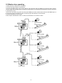
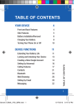
Single ArcPower 36 installation:
Multiple ArcPower 36 installation:
Connect the DMX output of the first ArcPower 36 with the DMX input of the next ArcPower 36. Always connect
one output with the input of the next ArcPower 36 until all fixtures are connected.In this way,up to 32 fixtures
can be chained together.
At the last ArcPower 36 the data link has to be terminated with a terminator. A termination plug is simply a
RJ45 connector with a 120 Ω resistor between pins Data (–) and Data (+).Plug terminator in the DMX output
of the last ArcPower 36.
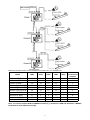
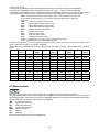
Maximum number of LEDs connected to the one ArcPower 36 is 42 (but maximum12 LEDs per colour).
Maximum possible number of LED modules connected to the one ArcPower 36:
Model
total
LEDs
Red
LEDs
Green
LEDs
Blue
LEDs
White
LEDs
Max.number
of connected
modules
ArcLine 12 RGB
ArcLine 24 RGB
ArcLine 36 RGB
ArcLine Optic 12 RGB
ArcLine Optic 24 RGB
ArcLine Optic 36 RGB
ArcSource 3 RGB
ArcSource 6 RGB
ArcSource 12 RGB
ArcSource 7 RGBW
12
24
36
12
24
36
3
6
12
7
4
8
12
4
8
12
1
2
4
2
4
8
12
4
8
12
1
2
4
2
4
8
12
4
8
12
1
2
4
2
1
3
1
1
3
1
1
12
6
3
6
Note: You cannot combine RGB and RGBW modules (e.g. ArcSource 6 RGB and ArcSource 7 RGBW)
each other as white LEDs will not light.
5.2.Master-slave operating
1.Unplug from the mains before installation.
2.Connect the LED module to the fixtures.
3.Connect the DMX output of the master fixture in the data-chain with the DMX input of the first slave. Always
connect output with the input of the next slave until all slaves are connected.Up to 32 fixtures can be connected
in master/slave chain
4.Insert the termination plug (with 120 Ohm) into DMX input of the master fixture and into the DMX output of
the last slave fixture in the link in order to ensure proper transmission on the data link.
5.Connect the fixtures to the mains.
6.See chapter "Stand-alone mode" in order to set the fixture as a master or slave.
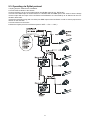
5.3. Operating via DyNet protocol
1.Unplug from the mains before installation.
2.Connect LED modules to the fixtures.
Connect first fixture to the control panel which uses DyNet protocol (e.g. DLP 8100)
3.Connect the DMX output of the first fixture in a data link with the DMX input of the second fixture. Always
connect output with the input of the next fixture until all fixtures are connected.Up to 32 fixtures can be connected in data chain.
4.Insert the termination plug (with 120 Ohm) into DMX output of the last fixture in order to ensure proper transmission on the data link.
5.Connect fixtures to the mains
6.Select the DyNet protocol on all fixtures (menu "SPE"---> Prt---> "dYn").
A description of each byte in DyNet protocol is the following:
Byte 0: 1C - hexadecimal Logical Message Byte 1: 01 - Area
Byte 2: 00 – Channel level
Byte 3: 80 - Channel
Byte 4: ff – Channel Offset
Byte 5: 00 – Fade Rate
Byte 6: FF
Byte 7: 1C Checksum
(fixed value)
(fixed value)
Area - (0 to 255), as set on the Arcpower to give a unique address for each Arcpower unit (i.e. DMX base
address)
Channel Level - (0 to 255), level - 01=100%, FF=0%
Channel - (80 to 83), 80= channel 1, 81= channel 2, 82= channel 3, 83= channel 4, (see Channel Offset
if more than 4 channels)
Channel Offset - (0-255), default (FF)- channel offset in blocks of 4: (FF = CH 1-4, 00 = CH 5-8,
01 = CH 9-12, etc up to 3E = CH 253-256 )
Fade Rate - (0-255), fade rate with 1 second resolution (0= 0 seconds, 255= 255 seconds)
Checksum - (0-255), checksum Byte - used to ensure the integrity of the packet.
Negative two's compliment of the preceding 7 bytes.
Example 1:
0x1C,0x10,0x00,0x80,0xff,0x05,0xff,0x52
This would control channel 1 (i.e. Red) of Arcpower unit, address 16 to a Level of 100% with a fade of 5
seconds.
Example 2:
0x1C,0x05,0xCC,0x82,0xff,0x0A,0xff,0x52
This would control channel 3 (i.e. Blue) of Arcpower unit, address 5 to a level of 20% with a fade of 10
seconds.
10
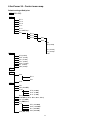
6.ArcPower 36 - Control menu map
Default settings=Bold print
001 (001-506)
PrG
E.P.1
E.P.2
E.P.3
P.01
:
P.10
Aut (OFF,On)
EdI.
E.P.1
E.P.2
E.P.3
S.01
:
S.50
End
rEd (0-255)
:
:
FA.t.(0-255)
S.tI. (0-255)
MAn. COP.
rEd (0-255)
GrE. (0-255)
bLu. (0-255)
Whi. (0-255)
MAC. (0-255)
Str. (0-255)
diM. (0-255)
tSt
St.A.
MSt.
SLA.
E.P.1
:
P10
SPE.
VEr.
bAL.(On,OFF)
C.bA.
rE.b. (0-200)
Gr.b. (0-255)
bL.b. (0-215)
Zon (Z.00-Z.09)
d.MP(Mo.1, Mo.2, Mo.3, Mo.4, Mo.5)
i.bL (On,OFF)
Prt (dMH,dYn)
C.Li
rEd. (128-255)
GrE. (128-255)
bLu (128-255)
Whi (128-255)
UPd.(No,YES)
11
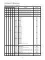
7.ArcPower 36 - DMX protocol
version 2.0 (software version 5.1 and higher)
Mode/Channel
1
2
3
4
5
1
1
1
1
1
Value
Function
Type
of control
0-255
RED LEDs
Red LEDs saturation control (0-100%)
proportional
proportional
2
2
2
2
2
0-255
GREEN LEDs
Green LEDs saturation control (0-100%)
3
3
3
3
3
0-255
BLUE LEDs
Blue LEDs saturation control (0-100%)
proportional
0-255
WHITE LEDs
White LEDs saturation control (0-100%)
proportional
4
4
4
0-7
8-15
16-23
24-31
32-39
40-47
48-55
56-63
64-71
72-79
80-87
88-95
96-103
104-111
112-119
120-127
128-135
136-143
142-151
152-159
160-167
168-175
176-183
184-191
192-199
200-207
208-215
216-223
224-231
232-239
240-247
248-255
5
5
6
6
7
0-31
32-63
64-95
96-127
128-143
144-159
160-191
192-223
224-255
4
0-255
MACRO SELECTION
No function
Macro 1
Macro 2
Macro 3
Macro 4
Macro 5
Macro 6
Macro 7
Macro 8
Macro 9
Macro 10
Macro 11
Macro 12
Macro 13
Macro 14
Macro 15
Macro 16
Macro 17
Macro 18
Macro 19
Macro 20
Macro 21
Macro 22
Macro 23
Macro 24
Macro 25
Macro 26
Macro 27
Macro 28
Macro 29
Macro 30
Rainbow effect with variable speed
step
step
step
step
step
step
step
step
step
step
step
step
step
step
step
step
step
step
step
step
step
step
step
step
step
step
step
step
step
step
step
proportional
SHUTTER/STROBE
Shutter closed
Shutter open
Strobe-effect from slow to fast
Shutter open
Opening pulses in sequences slow--> fast
Closing pulses in sequences fast --> slow
Shutter open
Random strobe-effects from slow to fast
Shutter open
step
step
proportional
step
proportional
proportional
step
proportional
step
DIMMER
Dimmer intensity from 0% to 100%
proportional
12
8.Control board
The control panel situated on the top cover of the ArcPower 36 allows DMX addressing,calling build-in programs
and setting the fixture behaviour
Control elements:
[ENTER] button- enters menu,confirms adjusted values and leaves menu.
,
[UP] button and[DOWN] button- moves between menu items on the the same level, sets values.
In order to leave the menu without saving value,press [UP] and [DOWN ] at the same time.
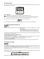
After switching on the ArcPower 36 ,the display shows the initial DMX address:
Use [UP],[DOWN] to browse through the menu. To select a function or submenu,press [ENTER].
8.1 Addressing the ArcPower 36
The fixture can be uperatated in the two modes:DMX mode-fixture is controlled via DMX 512 by an external
DMX controller
Stand-alone mode - fixture uses build-in programs and is able to control other fixtures in the master/slave chain.
See the chapter "Stand-alone mode" for detail description.
For DMX mode is important the DMX start address that is defined as the first channel from which the ArcPower
36 will respond to the DMX controller.
Setting the DMX start channel for DMX operating:
1. Connect ArcPower 36 to the mains.
2. Browse through the menu by pressing the [UP] and [DOWN] buttons until the display shows current addres
"001".Confirm by pressing [ENTER] button and "001" will start to flash frequently.
3. Use the [UP] and [Down] buttons to select the desired address.
4. Confirm by pressing [ENTER].
After having addressed ArcPower 36, you may now start operating ArcPower 36 via your DMX controller.
8.2 Program running
By enter to this menu a complete overview of all programs is offered,from which the program to be run can
be selected by pressing [ENTER].Selected program runs in a loop.The fixture includes 10 built-in programs
(P.01-P.10) and 3 free editable programs (E.P.1-E.P.3),each up to 50 steps.
If Item "AUt" is On,the fixture in DMX mode will remember last running program and this program will run after
switching on the fixture.
Each program step has a fade time-the time during which effects go to the current step and a Standing time-the time,during which effects last in the current step.
Programming procedure:
13
1. Enter "EdI." menu
2. Press [UP] or [DOWN] to select the desired program which you wish to edit and press [ENTER].
3. Press [UP] or [DOWN] to select the desired program step ("S.01" - "S.50") and press [ENTER].
4. Press [UP] or [DOWN] to select the desired item and press [ENTER]-button.Now you can edit by using [UP]
or [DOWN] buttons the DMX values selected item (the list of items depends on selected DMX mode):
End. - a total number of the program steps (value 1-50).This value you must set
before start programming(e.g. if you want to create program with 10 steps,set End=10).
rED
- a red LED saturation,value 0-255
GrE. - a green LED saturation,value 0-255
bLu. - a blue LED saturation,value 0-255
Whi. - a white LED saturation,value 0-255
MAC. - a macro selection,value 0-255
Str.
- a strobe,value 0-255
dim. - a dimmer,value 0-255
FA.t. - fade time,value 0-255 *
S.tI. - standing time,value 0-255 *
COP. - copying the current prog. step to the next prog. step.
Press [ENTER]-button to confirm adjusted value .
5.Repeat steps 3 and 4 for next prog.step.If you want to copy current prog. step to the next prog.step, select
option "COP."and confirm it by pressing [ENTER].
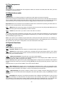
*Both Fade time and Standing time use the same conversion table in order to convert DMX value to the time
value:
DMX
Time
[sec.]
DMX
Time
[min.]
DMX
Time
[min.]
DMX
Time
[min.]
DMX
Time
[min.]
1
0.1
50
4.2
105
18.4
160
42.7
215
77
2
0.4
55
5
110
20.2
165
45.4
220
80.7
5
2.5
60
6
115
22
170
48.2
225
84.4
10
10
65
7
120
24
175
51
230
88.2
15
22.5
70
8.2
125
26
180
54
235
92
20
40
75
9.4
130
28.2
185
57
240
96
25
62.5
80
10.7
135
30.4
190
60.2
245
100
30
90
85
12
140
32.7
195
63.4
250
104
35
122.5
90
13.5
145
35
200
66.7
255
108
40
160
95
15
150
37.5
205
70
45
202.5
100
16.7
155
40
210
73.5
Exact expression of the time value follows the formula: time[sec.]=(DMX value)2/10.
8.3 Manual mode
This menu gives access to the control of the fixture channels by means of the control buttons.
Use [UP] and [DOWN] buttons until the display shows "MAn." menu.Press [ENTER] button and by using [UP]
and [DOWN] buttons select desired effect,press [ENTER] and and by using [UP] and [DOWN] buttons adjust
desired DMX value for selected effect.Confirm by [ENTER].
rED
a red LED saturation
GrE. a green LED saturation
bLu. a blue LED saturation
Whi. a white LED saturation
MAC a macro selection
Str.
a strobe
dim. a dimmer
The list of items depends on selected DMX mode.
14
8.4 Test sequences
Use the item to run a special demo-test sequences without an external controller,which will show you some
possibilities of using the fixture.
8.5 Stand-alone mode
Select this menu to set fixture behaviour in stand-alone mode without an external controller.
Synchronous operation of multiple fixtures requires that they must be connected on a data link and one of them is
set as a master ("MSt") and the rest as the slaves ("SLA").Only one fixture can be set as the master.The slaves
mimic the behavior of the master.Effect actions are triggered by an internal timer of the master fixture.
Important!:Disconect the fixtures from the DMX controller before master/slave operating ,otherwise data collisions can occur and the fixtures will not work properly!
MSt. --- Master.Enter this menu if you want to set the the fixture as a master.Use [UP] and [DOWN] buttons to
select desired program and press [ENTER] to confirm selection.
SLA. --- Slave.Enter this menu if you want to set the the fixture as a slave.
The master fixture starts simultaneous program start in the other slave fixtures.All fixtures are synchronized
in every prog.steps.The fixtures run their programs repeatedly (e.g. if master runs its program "P05",all slaves
will be executed program "P05" too).
Note: If the master runs its editable program (EP1,EP2 or EP3),all slaves will execute their own editable programs (EP1,EP2 or EP3) according the master,but both fade time (FA.t.) and standing time (S.tI.) for each step
will be taken from the master´s step (slaves´ times are eliminated in each step).
8.6 Special functions
Use this menu for special services.
VEr. --- Software Version.Select this function to read the number of the fixture software.
bAL. --- Balance.Select this function to enable (On) or disable (OFF) the white balance which is set in "White
colour balance" menu below.If this function is set OFF,ArcPower 36 will use maximum values (255) of saturation for red, green and blue channel.
C.bA. --- White colour balance. Using this menu you can set white balance:
1. Browse through the menu by pressing the [UP] and [DOWN] buttons until the display shows "C.bA." menu.Press
[ENTER] button and "rE.b." will appear on the display.
2.Press [ENTER] button again and use [UP] and [DOWN] buttons to adjust the new maximum value required
for the red channel.Confirm your choice by pressing [ENTER].Use the [UP] and [Down] buttons to select next
colour.
3.Repeat step 2 for green channel "Gr.b." and for blue channel "bL.b".
Zon. --- Zone selecting.The number of the zone distinguishes individual drivers which are controled via RS232 interface.Use [UP] and [DOWN] buttons to select desired zone (from 0 to 9) and press [ENTER] to confirm
selection.For futher information see chapter "Control of the ArcPower 36 via RS-232 ".
d.MP. --- DMX presetting.The function enables to select from the 5 DMX- channels settings.Use [UP] and
[DOWN] buttons to select desired channel mode(“Mo.1,Mo.2,Mo.3,Mo.4,Mo.5”) and press [ENTER] to confirm
selection.
i.bL. --- Initial blink.If this function is on,ArcPower 36 makes auto-calibration (All LEDs light on 100% for short
time) after switching it on.If this function is set off,you have to set manually every colour on max.brightness
after switching on the driver before starting regular operating.This action should last min. one second.In this
moment, the ArcPower 36 finds out the load connected to its LED output and makes auto-calibration.
15
Prt --- Protocol selection - Selects a required communication protocol.
dMH - the fixture will communicate using DMX 512 signal.
dYn - the fixture will communicate using the DyNet protocol.
C.Li. --- Current limiting.The menu item allows to reduce a current-carrying capacity of each LED branch (colour) in order to keep a declared lifetime of LED modules.The situation can occur if you operate LED modules
at an higher ambient temperature than is recommended (40°C).
The current-carrying capacity can be changed in a range of 350 - 175 mA (255-128) linearly.A default value is
255 (350 mA).
To adjust the current limiting:
1. Browse through the menu by pressing the [UP] and [DOWN] buttons until the display shows "C.Li." menu.
Press [ENTER] button and "rEd" item will appear on the display.
2.Press [ENTER] button again and use [UP] and [DOWN] buttons to select desired value. Confirm this value
by pressing [ENTER].Use the [UP] and [Down] buttons to select next colour.
3.Repeat step 2 for items "GrE", "bLu" and "Whi".
UPd. --- Software update - Using this function you can update software in the fixture via PC and serial link.
The following are required in order to update software:
- PC running Windows 95/98/2000/XP or Linux
- DMX Software Uploader
- Flash cable RS232/DMX (No.13050624)
Note1:Software update should execute a qualified person.If you lack qualification, do not attempt the update
yourself and ask for help your ANOLIS distributor.
Note 2:DMX address,programs and all settings will be set to their default values.
To update software in the fixture:
1.Installation of DMX Software Uploader:
1.DMX Software Uploader program is available from the ANOLIS web site at WWW.anolis.cz.
2.Make a new directory ( e.g. ANOLIS_Uploader) on your hard disk and download the software to it.
3.Unpack the program from the archives. Program file has name:DSU_name of corresponding
fixture_SoftwareID.SoftwareID describes the versions of fixture software included in DMX Software Uploader. Higher number means later software versions.
2.Fixture software updating:
1.Determine which of your COM port is available on your PC and connect it with to the DMX input
of the fixture using the Flash cable. Do not extend this cable! Disconnect the fixture from the
other fixtures in DMX chain! Turn on the computer and the fixture.
2.Switch the fixture to the update mode by selecting the option Software update in menu Special
Functions on the fixture control panel:SPE-->UPd-->yES.(From this option you cannot return back to the main menu. If you do not want to continue in software update, you have to switch off and on the fixture to leave this option!)
3.It is recommended that you exit all programs before running the Software Uploader.
4.Start the Software Uploader program. Select desired COM and then click Connect button.
If the conection is OK, click Start Uploading button to start uploading. It will take several minutes to perform software update.All processors will be updated (including processors with the same software version).
If you wish to update only later versions of processors, enable the Incremental Update check box.
Avoid interrupting the process. Update status is being displayed in the list window.
When the update is finished, the line with the text “The fixture is successfuly updated‘ will appear
in this window and the fixture will reset with the new software.
Note: In the case of interruption of the upload process (e.g. power cut), the fixture remains in the update mode
and you have to repeat the software update again.
For example: The fixture was switched off before finishing software upload. After switching the fixture on again,
the fixture is still in the update mode and the display is dark. Restart the Software Uploader program and repeat
software update from your PC.
16
9.Control of the ArcPower 36 via RS-232
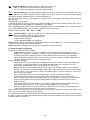
9.1Wiring an RS-232 serial port
9-pin D connector (male)
Front view of the socket:
Pin 1: Not connected
Pin 2: Received Data
Pin 3: Transmitted Data
Pin 4:
Pin 5: Signal Ground
Pin 6:
Pin 7:
Pin 8:
Pin 9: Not connected
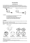
RS-232 cable:
9-pin D connector- female
ArcPower driver
9-pin D connector - female
PC
Pin 1: Pin 1: Pin 2: Received Data
Pin 2: Received Data
Pin 3: Transmited data
Pin 3: Transmited data
Pin 4: Pin 4:
Pin 5: Signal ground
Pin 5: Signal ground
Pin 6: Pin 6:
Pin 7: Pin 7:
Pin 8: Pin 8:
Pin 9: Pin 9:
The maximum cable length according to the standard is 15 metres or the cable length equals to a capacitance
of 2500 pF.
9.2 Selecting a zone
The number of the zone distinguishes individual drivers which are controled via RS-232 interface.
Select SPE in main menu of the ArPower 36 ,press [ENTER],use [UP] and [DOWN] buttons to select Zon.
The option enables to select desired number of the zone (from 0 to 9).Press [ENTER],use [UP] and [DOWN]
buttons to select zone number and press [ENTER] to confirm selection.
9.3 Setting a serial port of PC
The serial port of your personal computer hould be configured as follows:
9600 Baud,8 Data Bits,Non Parity,One Stop Bit,No Flow Control Required.
9.4 Zone commands
The ArcPower 36 uses the 3 types of the zone commands which can be used in a suitable software running
on PC.
All zone commands stated below have to be send to the ArcPower 36 in ASCII codes.
Type 1: Selection of the preset colours
The syntax of the command is:
zone Z red;
zone Z green;
17
zone Z blue;
zone Z white;
zone Z yellow;
zone Z cyan;
zone Z magenta;
zone Z blackout;
Z ...........means number of the zone (0-9)
red/green/blue/white/yellow/cyan/magenta....determines colour
blackout.......closes light output
;.............means end of character sequence
Examples: zone 4 green;
zone 0 blackout;
Type 2: Colour mixing-RGB
The syntax of the command is:
zone Z r,g,b;
Z............ means number of zone (0-9)
r .............means DMX value of the red colour(0-255)
g ............means DMX value of the green colour (0-255)
b ............means DMX value of the blue colour (0-255)
; .............means end of character sequence
, ..............values of colours have to be separated by a comma.
Examples: zone 0 234,126,165;
zone 1 5,18,28;
Type 3: Colour mixing-RGBW
The syntax of the command is:
zone Z r,g,b,w;
Z............ means number of zone (0-9)
r .............means DMX value of the red colour(0-255)
g ............means DMX value of the green colour (0-255)
b ............means DMX value of the blue colour (0-255)
w ............means DMX value of the white colour (0-255)
; .............means end of character sequence
, ..............values of colours have to be separated by a comma.
Examples: zone 0 156,145,171,211;
zone 1 5,18,28,148;
18
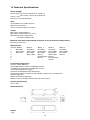
10.Technical Specifications:
Power supply:
Input Voltage: CE version:100-240 V AC, 50/60 Hz
ETL version: 100-120 V AC,50/60 Hz
Fuse:T 1.25A
Max.Pover Consumption:60VA
Input:
Control:DMX 512 or DyNet protocol
DMX connection:RJ45
RS 232 connection:9-pin D connector
Output:
Max.Output Voltage:48V DC
Max.Output current:350mA per colour
Max.load: 36 LEDs in RGB mode
42 LEDs in RGBW mode
Maximum total cable length between Arcpower 36 and all connected LED modules:
80 metres at max.load.
DMX channels:
Channel Mode 1
Mode 2
Mode 3
1
Red LEDs Red LEDs
Red LEDs
2
Green LEDs Green LEDs Green LEDs
3
Blue LEDs
Blue LEDs
Blue LEDs
4
White LEDs
Macros
5
Shutter/Strobe
6
Dimmer
7
Mode 4
Red LEDs
Green LEDs
Blue LEDs
White LEDs
Macros
Shutter/Strobe
Dimmer
Mode 5
Red LEDs
Green LEDs
Blue LEDs
Dimmer
Control and programming:
Protocol: USITT DMX-512
Three DMX protocol modes for RGB light sources
Two DMX protocol modes for RGBW light sources
Control options:DMX,Auto-trigger
Operation modes:Master/Slave,Stand alone
Programs:10 build-in programs+3 user editable programs up to 50 steps each
Display:3 digit LED
White colour balance adjusting
Manual control of all DMX channels with LED control panel
Operating temperature:
-10°C/+40°C
Dimensions(mm):
Weight:
1.1kg
19
Accessories:
Cable joiner...............1piece (No.13050691)
Optional accessories:
Adaptor RJ45/DMX 3 pin.......No.13050730
Adaptor RJ45/DMX 5 pin.......No.13050731
11 Replacing the fuse
1.Before replacing the fuse, unplug mains lead!
2.Unscrew the fuse holder on the rear side of the ArcPower 36 with a fitting screwdriver from the housing (anticlockwise).
3.Remove the old fuse from the fuse holder.
4.Install the new fuse in the fuse holder.
5.Replace the fuse holder in the housing and fix it.
Specifications are subject to change without notice.
20
21