1
Version 1.4
ArcPower 16x12
Table of contents
1. Safety instructions.......................................................................................................... 3
2. Operating determinations............................................................................................... 3
3.Description of the ArcPower 16x12................................................................................ 4
4.Installation........................................................................................................................ 4
4.1.Connection to the mains:............................................................................................ 4
4.2.Mounting the ArcPower 16x12.................................................................................... 5
4.3.Conection cables......................................................................................................... 5
5 DMX operation ................................................................................................................. 6
5.1 Single ArcPower 16x12 installation............................................................................. 6
5.2 Multiple ArcPower 16x12 installation.......................................................................... 7
6.ArcPower 16x12 - Control menu map............................................................................. 8
7. ArcPower 16x12 - DMX protocol ( version 1.2)............................................................ 10
8.Control board.................................................................................................................. 16
8.1 Addressing the ArcPower 16x12 . ............................................................................ 16
8.2 Fixture information.................................................................................................... 16
8.3 Manual mode............................................................................................................ 17
8.4 Test sequences......................................................................................................... 17
8.5 Stand-alone mode..................................................................................................... 17
8.6 Special functions....................................................................................................... 18
9.Technical Specifications:.............................................................................................. 21
10. Replacing the fuse ..................................................................................................... 22
CAUTION!
Unplug mains lead before opening the housing!
FOR YOUR OWN SAFETY, PLEASE READ THIS USER MANUAL CAREFULLY
BEFORE YOU INITIAL START - UP!
1. Safety instructions
Every person involved with installation and maintenance of this product has to:
- be qualilfied
- follow the instructions of this manual
CAUTION!
Be careful with your operations. With a high voltage you can suffer
a dangerous electric shock when touching the wires inside the unit!
This product has left our premises in absolutely perfect condition. In order to maintain this condition and to
ensure a safe operation, it is absolutely necessary for the user to follow the safety instructions and warning
notes written in this manual.
To prevent from danger of accident ,the device has to be fixed on flat, non-flammable surface in compliance with the installing instruction included in this manual.
Important:
The manufacturer will not accept liability for any resulting damages caused by the non-observance of this
manual or any unauthorized modification to the product.
Always ground the unit.
The electric connection, repairs and servicing must be carried out by a qualified employee.
Do not connect this unit to a dimmer pack.
Use a source of AC power that complies with local building and electrical rules.AC power has to have both
overload and short circuit protection
2. Operating determinations
This product was designed for indoor use only.
If the unit has been exposed to drastic temperature fluctuation (e.g. after transportation), do not switch it on
immediately. The arising condensation water might damage your unit. Leave the unit switched off until it has
reached room temperature.
Avoid brute force when installing or operating the unit.
When choosing the installation-spot, please make sure that the unit is not exposed to extreme heat, moisture
or dust.
Only operate the unit after having checked that the housing is firmly closed and all screws are tightly fastened.
The maximum ambient temperature 40° C must never be exceeded.
Operate the unit only after having familiarized with its functions. Do not permit operation by persons not qualified for operating the unit. Most damages are the result of unprofessional operation!
Please use the original packaging if the product is to be transported.
Please consider that unauthorized modifications on the unit are forbidden due to safety reasons!
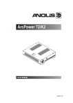
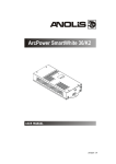
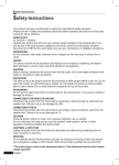
3.Description of the ArcPower 16x12
1 - Control board
2 - LED output zones
3 - DMX Input
4 - DMX Output
5 - Fuse holder
6 - Power cord
LED output zones (RGB operation)
LED output zones (RGBW operation)
DMX Input,Output
LED module Input
RJ45 socket Front view of the socket:
Pin 1: Not connected
Pin 2: Not connected
Pin 3: Not connected
Pin 4: Not connected
RJ45 socket
Front view of the socket:
Pin 1: Red LED +
Pin 2: Green LED +
Pin 3: Blue LED +
Pin 4: White LED +
Pin 5: +5V
Pin 6: Data +
Pin 7: Data Pin 8: GND
Pin 5: Red LED Pin 6: Green LED Pin 7: Blue LED Pin 8: White LED -
4.Installation
4.1.Connection to the mains:
The ArcPower 16x12 is equipped with auto-switching power supply that automatically adjusts to any 50/60Hz
AC power source from 100-240 Volts.
Carefully prepare the end of the the supply cord and fit a suitable plug.A 3-prong grounding-type plug must be
installed following the manufacturer´s instructions.The earth has to be connected!
Cord plug connection:
Cable Pin
International
Brown
Live Light blue
Neutral
Yellow/Green
Earth
L
N
This device falls under protection class I.Therefore the ArcPower 16x12 has to be
connected to a mains socket outlet with a protective earthing connection.
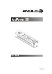
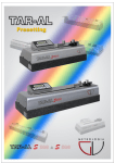
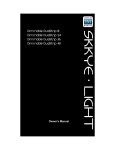
4.2.Mounting the ArcPower 16x12
The ArcPower 16x12 should be be placed on a non-flammable flat surface in any orientation and fixed by the
four screws.There are four mounting holes of a diameter 5 mm in housing of the driver. Ensure that instalation
place is enough ventilated.
Screws
Screws
Mounting hole
Flat surface
4.3.Conection cables
1.The adapter cable RJ45/XLR connects the ArcPower 16x12 to the DMX controller.If your DMX controller has
RJ45 socket for DMX output,use RJ45 patch cable for connection with the ArcPower 16x12.
RJ45 plug
View facing pins
DMX 512 XLR plug (male)
Front view of the plug
Pin 1: Not used
Pin 2: Not used
Pin 3: Not used
Pin 4: Not used
Pin 5: +5V
Pin 6: Data +
Pin 7: Data Pin 8: GND
Pin 1: GND
Pin 2: Data Pin 3: Data +
Pin 4: Not used
Pin 5: Not used
2.RJ45 patch cables category 5 that connect the ArcPower 16x12 each other are wired 1:1,that is,pins with the
same numbers are connected together.
Pin 1: Not used
Pin 2: Not used
Pin 3: Not used
Pin 4: Not used
Pin 5: +5V
Pin 6: Data +
Pin 7: Data -
Pin 8: GND
Pin 1: Not used
Pin 2: Not used
Pin 3: Not used
Pin 4: Not used
Pin 5: +5V
Pin 6: Data +
Pin 7: Data Pin 8: GND
5 DMX operation
1.Unplug from the mains before installation.
2.Connect the LED modules to the fixture according to the operation (RGB or RGBW).
3.Connect DMX controller to the fixture
4.Connect the fixture to the mains
5.Set the DMX address on the control board of the fixture (see chapter "Control board").
Warning!
Accidental connection DMX 512 Input/Output to non-DMX 512 device (e.g.Ethernet
network Hub) can damage the ArcPower 16x12.
Maximum total cable length between Arcpower 16x12 and all connected LED modules is 80 metres.
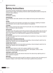
5.1 Single ArcPower 16x12 installation
1. RGB operation
Max. load per LED output zone: 12x1W
LED
Number of zones: 16
2. RGBW operation
The ArcPower 16x12 allows to operate 12 RGBW outputs (zones) and it is not necessary to change its menu
setting.
Note: Only 12 zones of the ArcPower 16x12 can be used for RGBW operation - see chapter 3 "Description of the ArcPower 16x12".
Max. load per LED output zone:
16x1W LED
Number of zones: 12
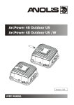
5.2 Multiple ArcPower 16x12 installation
Connect the DMX output of the first ArcPower 16x12 with the DMX input of the next ArcPower 16x12. Always
connect one output with the input of the next ArcPower 16x12 until all fixtures are connected.In this way,up to
32 fixtures can be chained together.
At the last ArcPower 16x12 the data link has to be terminated with a terminator. A termination plug is simply a
RJ45 connector with a 120 Ω resistor between pins Data (–) and Data (+).Plug terminator in the DMX output
of the last ArcPower 16x12.
6.ArcPower 16x12 - Control menu map
Default settings=Bold print
A001 (001-464)
Info
dM.In
tEMP
VErS
MAn.C.
VEr1
VEr2
rEd.1 (0-255)
GrE.1 (0-255)
bLu.1 (0-255)
:
Stro. (0-255)
dimr (0-255)
tESt.
St.AL.
Auto
PLAY
Edit
OFF
tESt
EPG.1
EPG.2
tESt
EPG1
EPG2
EPG1
EPG2
St.01
:
St.60
SPEC
dM.Pr. (Mod,1,Mod2, Mod3.....Mod 6)
M.F.t.i. (0.1...2.0----25.5)
CALi
rEd.1 (0-255)
:
bL.16 (0-255)
Stor.
bALA. (On,OFF)
C.bAL.
rEd.b. (0-255)
GrE.b.(0-255)
bLu.b. (0-255)
rEd 1 (0-255)
:
dimr. (0-255)
F.tim.(0-255)
S.tim. (0-255)
COPY
P.End. (1-64)
CHAr
EYE
LinE
i.bLi (On,Off)
dFSE (no,YES)
uPd (no,YES)
7. ArcPower 16x12 - DMX protocol - version 1.2)
RGB operation
Mode 1
Mode 2
Mode 3
Mode 4
Channel Channel Channel Channel
Value
Function
Type of
control
ZONE 1
1
1
1
1
2
2
2
2
3
3
3
3
0-255
Red LED 1
Red LED saturation control (0-100%)
proportional
0-255
Green LED 1
Green LED saturation control (0-100%)
proportional
0-255
Blue LED 1
Blue LED saturation control (0-100%)
proportional
ZONE 2
1
1
4
4
2
2
5
5
3
3
6
6
0-255
Red LED 2
Red LED saturation control (0-100%)
proportional
0-255
Green LED 2
Green LED saturation control (0-100%)
proportional
0-255
Blue LED 2
Blue LED saturation control (0-100%)
proportional
ZONE 3
1
1
7
7
2
2
8
8
3
3
9
9
0-255
Red LED 3
Red LED saturation control (0-100%)
proportional
0-255
Green LED 3
Green LED saturation control (0-100%)
proportional
0-255
Blue LED 3
Blue LED saturation control (0-100%)
proportional
ZONE 4
1
1
10
10
2
2
11
11
3
3
12
12
0-255
Red LED 4
Red LED saturation control (0-100%)
proportional
0-255
Green LED 4
Green LED saturation control (0-100%)
proportional
0-255
Blue LED 4
Blue LED saturation control (0-100%)
proportional
ZONE 5
1
1
13
13
2
2
14
14
3
3
15
15
0-255
Red LED 5
Red LED saturation control (0-100%)
proportional
0-255
Green LED 5
Green LED saturation control (0-100%)
proportional
0-255
Blue LED 5
Blue LED saturation control (0-100%)
proportional
ZONE 6
1
1
16
16
2
2
17
17
3
3
18
18
0-255
Red LED 6
Red LED saturation control (0-100%)
proportional
0-255
Green LED 6
Green LED saturation control (0-100%)
proportional
0-255
Blue LED 6
Blue LED saturation control (0-100%)
proportional
ZONE 7
1
1
19
19
2
2
20
20
3
3
21
21
0-255
Red LED 7
Red LED saturation control (0-100%)
proportional
0-255
Green LED 7
Green LED saturation control (0-100%)
proportional
0-255
Blue LED 7
Blue LED saturation control (0-100%)
proportional
ZONE 8
1
1
22
22
2
2
23
23
3
3
24
24
0-255
Red LED 8
Red LED saturation control (0-100%)
proportional
0-255
Green LED 8
Green LED saturation control (0-100%)
proportional
0-255
Blue LED 8
Blue LED saturation control (0-100%)
proportional
10
Mode 1
Mode 2
Mode 3
Mode 4
Channel Channel Channel Channel
Value
Function
Type of
control
ZONE 9
1
1
25
25
2
2
26
26
3
3
27
27
0-255
Red LED 9
Red LED saturation control (0-100%)
proportional
0-255
Green LED 9
Green LED saturation control (0-100%)
proportional
0-255
Blue LED 9
Blue LED saturation control (0-100%)
proportional
ZONE 10
1
1
28
28
2
2
29
29
3
3
30
30
0-255
Red LED 10
Red LED saturation control (0-100%)
proportional
0-255
Green LED 10
Green LED saturation control (0-100%)
proportional
0-255
Blue LED 10
Blue LED saturation control (0-100%)
proportional
ZONE 11
1
1
31
31
2
2
32
32
3
3
33
33
0-255
Red LED 11
Red LED saturation control (0-100%)
proportional
0-255
Green LED 11
Green LED saturation control (0-100%)
proportional
0-255
Blue LED 11
Blue LED saturation control (0-100%)
proportional
ZONE 12
1
1
34
34
2
2
35
35
3
3
36
36
0-255
Red LED 12
Red LED saturation control (0-100%)
proportional
0-255
Green LED 12
Green LED saturation control (0-100%)
proportional
0-255
Blue LED 12
Blue LED saturation control (0-100%)
proportional
ZONE 13
1
1
37
37
2
2
38
38
3
3
39
39
0-255
Red LED 13
Red LED saturation control (0-100%)
proportional
0-255
Green LED 13
Green LED saturation control (0-100%)
proportional
0-255
Blue LED 13
Blue LED saturation control (0-100%)
proportional
ZONE 14
1
2
3
1
2
3
40
41
42
40
41
42
0-255
Red LED 14
Red LED saturation control (0-100%)
proportional
0-255
Green LED 14
Green LED saturation control (0-100%)
proportional
0-255
Blue LED 14
Blue LED saturation control (0-100%)
proportional
ZONE 15
1
1
43
43
2
2
44
44
3
3
45
45
0-255
Red LED 15
Red LED saturation control (0-100%)
proportional
0-255
Green LED 15
Green LED saturation control (0-100%)
proportional
0-255
Blue LED 15
Blue LED saturation control (0-100%)
proportional
ZONE 16
1
1
46
46
2
2
47
47
3
3
48
48
0-255
Red LED 16
Red LED saturation control (0-100%)
proportional
0-255
Green LED 16
Green LED saturation control (0-100%)
proportional
0-255
Blue LED 16
Blue LED saturation control (0-100%)
proportional
11
Mode 1
Mode 2
Mode 3
Mode 4
Channel Channel Channel Channel
-
4
-
49
-
5
-
50
Value
0-31
32-63
64-95
96-127
128-143
144-159
160-255
0-255
Function
Type of
control
Shutter/Strobe
Shutter closed
Shutter open
Strobe-effect from slow to fast
Shutter open
Opening pulses in sequences slow--> fast
Closing pulses in sequences fast --> slow
Shutter open
step
step
proportional
step
proportional
proportional
step
DImmer
Dimmer intensity from 0% to 100%
proportional
12
RGBW operation
Mode 5
Mode 6
Channel Channel
Value
Function
Type of control
ZONE 2
1
1
2
2
3
3
4
4
0-255
Red LED 1
Red LED saturation control (0-100%)
proportional
0-255
Green LED 1
Green LED saturation control (0-100%)
proportional
0-255
Blue LED 1
Blue LED saturation control (0-100%)
proportional
0-255
White LED 1
White LED saturation control (0-100%)
proportional
ZONE 3
1
5
2
6
3
7
4
8
0-255
Red LED 2
Red LED saturation control (0-100%)
proportional
0-255
Green LED 2
Green LED saturation control (0-100%)
proportional
0-255
Blue LED 2
Blue LED saturation control (0-100%)
proportional
0-255
White LED 2
White LED saturation control (0-100%)
proportional
ZONE 4
1
9
2
10
3
11
4
12
0-255
Red LED 3
Red LED saturation control (0-100%)
proportional
0-255
Green LED 3
Green LED saturation control (0-100%)
proportional
0-255
Blue LED 3
Blue LED saturation control (0-100%)
proportional
0-255
White LED 3
White LED saturation control (0-100%)
proportional
0-255
Red LED 4
Red LED saturation control (0-100%)
proportional
0-255
Green LED 4
Green LED saturation control (0-100%)
proportional
0-255
Blue LED 4
Blue LED saturation control (0-100%)
proportional
0-255
White LED 4
White LED saturation control (0-100%)
proportional
0-255
Red LED 5
Red LED saturation control (0-100%)
proportional
0-255
Green LED 5
Green LED saturation control (0-100%)
proportional
0-255
Blue LED 5
Blue LED saturation control (0-100%)
proportional
0-255
White LED 5
White LED saturation control (0-100%)
proportional
ZONE 6
1
13
2
14
3
15
4
16
ZONE 7
1
17
2
18
3
19
4
20
ZONE 8
1
21
2
22
3
23
4
24
0-255
Red LED 6
Red LED saturation control (0-100%)
proportional
0-255
Green LED 6
Green LED saturation control (0-100%)
proportional
0-255
Blue LED 6
Blue LED saturation control (0-100%)
proportional
0-255
White LED 6
White LED saturation control (0-100%)
proportional
13
Mode 5
Mode 6
Channel Channel
Value
Function
Type of control
ZONE 10
1
25
2
26
3
27
4
28
0-255
Red LED 7
Red LED saturation control (0-100%)
proportional
0-255
Green LED 7
Green LED saturation control (0-100%)
proportional
0-255
Blue LED 7
Blue LED saturation control (0-100%)
proportional
0-255
White LED 7
White LED saturation control (0-100%)
proportional
0-255
Red LED 8
Red LED saturation control (0-100%)
proportional
0-255
Green LED 8
Green LED saturation control (0-100%)
proportional
0-255
Blue LED 8
Blue LED saturation control (0-100%)
proportional
0-255
White LED 8
White LED saturation control (0-100%)
proportional
0-255
Red LED 9
Red LED saturation control (0-100%)
proportional
0-255
Green LED 9
Green LED saturation control (0-100%)
proportional
0-255
Blue LED 9
Blue LED saturation control (0-100%)
proportional
0-255
White LED 9
White LED saturation control (0-100%)
proportional
ZONE 11
1
29
2
30
3
31
4
32
ZONE 12
1
33
2
34
3
35
4
36
ZONE 14
1
37
2
38
3
39
4
40
0-255
Red LED 10
Red LED saturation control (0-100%)
proportional
0-255
Green LED 10
Green LED saturation control (0-100%)
proportional
0-255
Blue LED 10
Blue LED saturation control (0-100%)
proportional
0-255
White LED 10
White LED saturation control (0-100%)
proportional
ZONE 15
1
41
2
42
3
43
4
44
0-255
Red LED 11
Red LED saturation control (0-100%)
proportional
0-255
Green LED 11
Green LED saturation control (0-100%)
proportional
0-255
Blue LED 11
Blue LED saturation control (0-100%)
proportional
0-255
White LED 11
White LED saturation control (0-100%)
proportional
0-255
Red LED 12
Red LED saturation control (0-100%)
proportional
0-255
Green LED 12
Green LED saturation control (0-100%)
proportional
0-255
Blue LED 12
Blue LED saturation control (0-100%)
proportional
0-255
White LED 12
White LED saturation control (0-100%)
proportional
ZONE 16
1
45
2
46
3
47
4
48
14
Mode 5
Mode 6
Channel Channel
5
49
6
50
Value
0-31
32-63
64-95
96-127
128-143
144-159
160-255
0-255
Function
Type of control
Shutter/Strobe
Shutter closed
Shutter open
Strobe-effect from slow to fast
Shutter open
Opening pulses in sequences slow--> fast
Closing pulses in sequences fast --> slow
Shutter open
step
step
proportional
step
proportional
proportional
step
DImmer
Dimmer intensity from 0% to 100%
proportional
15
8.Control board
The control panel situated on the top cover of the ArcPower 16x12 allows DMX addressing and set
the fixture´s behaviour.
Control elements:
[ENTER] button- enters menu,confirms adjusted values and leaves menu.
,
[UP] button and[DOWN] button- moves between menu items on the the same level, sets values.
[ESCAPE] button- leaves the menu without saving value.
After switching on the ArcPower 16x12 ,the display shows the initial DMX address:
Use [UP],[DOWN] to browse through the menu. To select a function or submenu,press [ENTER].
8.1 Addressing the ArcPower 16x12
Setting the DMX start channel:
1. Connect the ArcPower 16x12 to the mains.
2. Browse through the menu by pressing the [UP] and [DOWN] buttons until the display shows current addres
"A001".Confirm by pressing [ENTER] button and "A001" will start to flash frequently.
3. Use the [UP] and [Down] buttons to select the desired address.
4. Confirm by pressing [ENTER].
After having addressed ArcPower 16x12, you may now start operating ArcPower 16x12 via your DMX controller.
8.2 Fixture information
Use this menu to read useful information about the fixture status.
To display desired information.
1. Use the UP/DOWN buttons to find the “ InFo“ menu.
2. Press the ENTER button.
3. Use the UP/DOWN buttons to select the required menu item.
4. Press the ENTER button to confirm the choice.
DM.In.---DMX values. Select this function to read DMX values of each channel received by the fixture.
tEMP --- Fixture Temperature. Select this menu to read the temperature of the fixture:
VErS. ---Software Versions. Select this function to read the software version of each board in the fixture .
16
8.3 Manual mode
Use this menu for control the fixture without connected DMX console.
Man.C. --- Manual effect control. Select this menu to control all channels via buttons of the control board.
To control fixture channels.
1.
Use the UP/DOWN buttons to find “ Man.C“ menu.
2.
Press the ENTER button.
3.
Use the UP/DOWN buttons to select desired effect (channel).
List of control channels:
“rEd.1-rE.16” - red LEDs saturations
“GrE.1.-Gr.16 “ - green LEDs saturations
“bLu.1-bL.16 “ - blue LEDs saturations
“Stro.“ - a strobe, shutter
“dinr“ - a dimmer
4.
Press the ENTER button and use the UP/DOWN buttons to set value , press the ENTER button to
confirm it.
8.4 Test sequences
Use the item to run a demo-test sequences without an external controller,which will show you some possibilities of using the fixture.
8.5 Stand-alone mode
Use this menu to run a program or to set a running program in the stand-alone operation - operation without
connected DMX controller
Auto --- Presetting playback.This function allows you to select the program which will be played continuously
in a loop after switching the fixture on.The fixture has two freely-programmable programs (EPG1-EPG2).
OFF --- The option disables "Auto" function.
tESt --- test program
EPG.1 --- program No.1
EPG.2 --- program No.2
PLAY --- Playing program.Select this menu to run a desired program immediately.
tESt --- The option starts test program
EPG.1 --- The option starts editable program No.1
EPG.2 --- The option starts editable program No.2
Select the program you wish and press [ENTER].The selected program starts running.By Pressing [ENTER]
again is possible to pause the program running.
Edit --- Editing a program. The fixture offers 2 freely editable programs (EPG.1, EPG.2) each up to 64 steps.
Every program step includes a fade time-the time taken by the step´s channel status to reach the desired level
and a step time-the total time occupied by the step in the program.
E.g. If “F.tim.“=5 second and “S.tim.“=20 second, effects will go to the desired position during 5 seconds and
after that they will stay in this position for 15 seconds before going to the next prog. step
1.
Use the UP/DOWN buttons to find “ St.AL.“ menu and press the ENTER button.
2.
Use the UP/DOWN buttons to select “Edit“ menu and press the ENTER button.
3.
Use the UP/DOWN buttons to select a program you want to edit (EPG.1, EPG.2) and press ENTER
button.
4.
Use the UP/DOWN buttons to select a desired program step ("St.01" - "St.64") and press ENTER
button.
5.
Use the UP/DOWN buttons to select a channel you want to edit and press the ENTER button.
List of editable items:
“P.End” - a total number of the program steps (value 1-64). This value should be set before start
17
Programming (e.g. if you want to create program with 10 steps, set P.End=10).
“rEd.1 - rE.16”- a red LEDs saturation (0-255)
“GrE.1 - Gr.16“ - a green LEDs saturation (0-255)
“bLu.1 - bL.16 “ -a blue LEDs saturation (0-255)
“Stro.“ - a strobe, shutter (0-255)
“dimr“ - a dimmer (0-255)
“F.tim.“ - a fade time, (0-25.5) seconds
“S.tim.“- step time, value (0-25.5) seconds
“COPY“. – this item duplicates the current prog. step to the next prog. step. The item “P.End” is increased
automatically.
6.
Use the UP/DOWN buttons to set a DMX value of the channel and then press the ENTER button.
7.
Use the UP/DOWN buttons to select next channel and press the ENTER button.
8.
After having set all channels in the current program step, press the MODE button to go by one
menu level back and select another program step.
8.6 Special functions
Use this menu for special services.
dM.Pr. --- DMX presetting.The function allows to select desired DMX mode.Use [UP] and [DOWN] buttons
to select desired channel mode (“Mod.1-Mod.6”) and press [ENTER] to confirm.For detail description of all
channels see DMX protocol.
M.F.ti. --- Max. fade time. Select this menu item to set a desired max. fade time (0-25.5 sec.). This adjusted
fade time influences fade of RGB and dimmer during DMX operation:
If time between two receiving DMX values is > than fade time set in the item M.F.ti., the entire adjusted fade
time will be used.
If time between two receiving DMX values is < than fade time set in the item M.F.ti., the adjusted fade time will
be reduced to fill entire time between the two receiving DMX values.
e.g. M.F.ti.=2sec. and fixture has received Red=0 DMX, after 5 seconds will receive Red=255 DMX. It means,
that red will go to full intensity during 2 seconds.
M.F.ti.=8 sec. and fixture has received Red=0 DMX, after 5 seconds will receive Red=255 DMX. It means, that
red will go to full intensity during 5 seconds. (Max, fade time is reduced from 8 sec. to 5 sec.).
Note: the value adjusted in the item M.F. ti. will not influence fade time set in the program steps.
CALi. --- LED intensity calibration.The menu allows you to adjust the max. light intensity of individual LEDs
(colour channels),e.g. the light intensity of all red LEDs connected to the channel 4.This action is suitable in case
that adjacent LEDs (e.g. in LED array) have a different light intensity (but these LEDs have to be connected to
the different zones of the ArcPower 16x12).
Use [UP] and [DOWN] buttons to select desired LED,press [ENTER] and adjust suitable light intensity (0-255)
using [UP] and [Down] buttons,confirm by pressing [ENTER].This adjusted light intensity is its maximum intensity
which can be reached if dimmer=255 DMX. After calibration all LEDs, select Stor. to save adjusted values.
bALA. --- Balance.Select this function to enable (On) or disable (OFF) the white balance which is set in "White
colour balance" menu below.If this function is set OFF,ArcPower 16x12 will use maximum value (255) of saturation for red, green and blue channels.
C.bAL. --- White colour balance. Using this menu you can set white balance:
1. Set all red,green and blue channels on maximum saturation(255)
2. Browse through the menu by pressing the [UP] and [DOWN] buttons until the display shows "C.bAL." menu.
Press [ENTER] button and "rEd.b." will appear on the display.
3.Press [ENTER] button again and use [UP] and [DOWN] buttons to adjust the new maximum value required
for the red channel.Confirm your choice by pressing [ENTER].Use the [UP] and [Down] buttons to select next
colour.
4.Repeat step 3 for green channel "GrE.b." and for blue channel "bLu.b".
CHAr. --- Dimmer characteristic. The option allows selection from the 2 dimming curves:
EYE - The dimming curve takes into account a gamma curve
LinE - Linear running of the dimming curve.
18
Use [UP] and [DOWN] buttons to select desired dimmer characteristic and press [ENTER] to confirm.
i.bLi. --- Initial blink. If this function is on, the ArcPower 16x12 makes auto-calibration (LED modules, one by
one, lit on 100% for short time,) after switching it on. During this action the ArcPower 16x12 finds out the load
connected to its LED outputs and makes auto-calibration. If the LED modules will not be changed (still the
same LED modules connected), after first auto-calibration you can set "i.bLi" at Off, as autocalibration takes
some time. In case, that some LED modules will be changed (even the same type) you should perform autocalibration again.
In. Po. - Use the menu to set all effects to the desired positions at which they will stay after switching the fixture
on without DMX signal connected.
dF.SE. --- Default Settings .Select this option to reset all fixture personalities to the default values.
uPd. --- Software update - The menu item allows you to update software in the fixture via either serial or USB
port of PC.
The following are required in order to update software:
- PC running Windows 95/98/2000/XP or Linux
- DMX Software Uploader
- Flash cable RS232/DMX No.13050624 (if you want to use a serial port of PC)
- Robe Universal Interface (if you want to use an USB port of PC)
Note1: Software update should execute a qualified person. If you lack qualification, do not attempt the update
yourself and ask for help your ROBE distributor.
Note 2: DMX address, programs 1-2 and all items in the menu "SPEC" will be set to their default values.
To update software in the fixture:
I. Installation of the DMX Software Uploader.
1. DMX Software Uploader program is available from the Anolis web site at WWW.anolis.cz.
2. Make a new directory ( e.g. Robe_Uploader) on your hard disk and download the software into it.
3. Unpack the program from the archive.
II.Fixture software updating.
1.
Determine which of your port is available on your PC and connect it:
-
with the DMX input of the fixture if you using the flash cable RS232/DMX
-
with the DMX input of the Robe Universal Interface if you using the USB cable.
Disconnect the fixture from the other fixtures in a DMX chain. Turn both the computer and the fixture on. Make
sure the lamp is switched off (only if the fixture involves a lamp).
2.
Switch the driver to the updating mode:
1
Use the UP/DOWN buttons to find “SPEC.“ menu.
2
Press the ENTER button.
3
Use the UP/DOWN buttons to select “ uPd.“ item.
4
Press the ENTER button
5
Use the UP/DOWN buttons to select “ yES“ option
6
Press the ENTER button
Note: If you do not want to continue in software update, you have to switch off and on the fixture
to escape from this menu.
3. We recommend to cancel all running programs before start of the Software Uploader.
4. Run the Software Uploader program. Select desired COM and then click on the Connect button.
19
If the connection is OK, click on the Start Uploading button to start uploading. It will take several minutes
to perform software update. If the option "Incremental Update" is not checked, all processors will be
updated (including processors with the same software version).
If you wish to update only later versions of processors, check the Incremental Update box.
Avoid interrupting the process. Update status is being displayed in the Info Box window.
When the update is finished, the line with the text “The fixture is successfully updated‘will appear in
this window and the fixture will reset with the new software.
Note: In the case of an interruption of the upload process (e.g. power cut), the driver keeps the updating mode
and you have to repeat the software update again.
20
9.Technical Specifications:
Power supply:
Input Voltage: 100-240 V AC, 50/60 Hz
Fuse:T 2 A H
Max.Pover Consumption:170VA
Input:
Control:DMX 512
DMX connection:RJ45
Output:
Max.Output Voltage:12V DC
Max.Output current per zone:350mA per colour
RGB operation
LED zones: 16
Max.load per zone: 12 x 1W LED
Total max.load: 16x12 LEDs
RGBW operation
LED zones: 12
Max.load per zone: 16 x 1W LED
Total max.load: 12x16 LEDs
Max. total cable length between one zone of the Arcpower 16x12 and connected LED module:20 metres
Note: Sum of cable lengths between zones 1-8 must not exceed 80 metres.
Sum of cable lengths between zones 9-16 must not exceed 80 metres.
DMX channels:
Mode 1: 3
Mode 2: 5
Mode 3: 48
Mode 4: 50
Mode 5: 6
Mode 6: 50
Control and programming:
Protocol: USITT DMX-512
Operating modes:DMX,Stand-alone
Display:4 digit LED
White colour balance adjusting
Manual control of all DMX channels via control panel
Programs: 2 freely programmable, each up to 64 steps
Operating temperature:
-10°C/+40°C
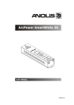
Dimensions(mm):
21
Weight:
2 kg
Total heat dissipation
510 BTU/h (calculated)
Accessories:
Cable joiner (No.13050691)...............16 pieces
Optional accessories:
Adaptor RJ45/DMX 3 pin.......No.13050730
Adaptor RJ45/DMX 5 pin.......No.13050731
10. Replacing the fuse
1.Before replacing the fuse, unplug mains lead!
2.Unscrew the fuse holder on the rear side of the ArcPower 16x12 with a fitting screwdriver from the housing
(anti-clockwise).
3.Remove the old fuse from the fuse holder.
4.Install the new fuse in the fuse holder.
5.Replace the fuse holder in the housing and fix it.
Specifications are subject to change without notice.
July 15, 2014
22
23