1
Principles of Operation
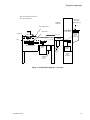
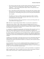
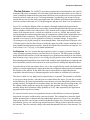
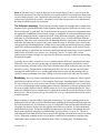
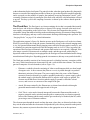
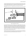
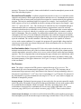
System Overview Figure 4 shows a block diagram of an XT100 system. The repair process
begins when the operator loads a mask carrier (also known as an RSP, or Reticle SMIF Pod) into
the load port module. The operator initiates the automated sample loading process by clicking the
Load button on the Load/Unload dialog box in the software user interface.
A robotic system transfers the mask from the load port module to the loadlock at the front of the
work chamber. Next, the loadlock door closes, and the loadlock is pumped down to low pressure
so as not to introduce abnormally high pressures in the workchamber. After the loadlock is pumped
down, the mask is transferred (via another robotic transfer system) to the mask holder on the sample
positioning stage. An automated clamping/positioning system on the mask holder aligns the mask,
and the mask is then ready to be positioned for imaging and repair procedures.
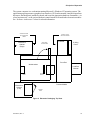
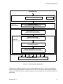
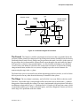
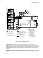
The XT100 system is comprised of several subsystems, each of which has its own software
subsystem, power connections, communications node, and hardware controller. The hardware and
cabling for these subsystems are mounted in racks in the left and right electronic cabinets, and are
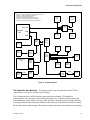
normally not accessible to the system operator. Figure 5 shows a top view of the major system
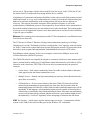
components. Figure 6 and figure 7 show the location of the modules in the right and left electronics
cabinets.
800-000071, Rev. A
24
Principles of Operation
SMIF - Standard Mechanical Interface
MCP - Microchannel Plate
Mask Carrier
(AKA RSP Reticle SMIF Pod)
Chemical
Cabinets
Gas Nozzle (Funnel)
Front End
Flood Gun
Ion
Column
Mask Holder
(mask loading)
Load Port
Module
(AKA
SMIF Pod)
= Mask path
Workchamber
Loadlock
MCP
Stage
Stage positioning
Chamber
Robot
Loadlock
Turbo
Pump
Chamber
Turbo
Pump
Mask
Transfer
Robot
Transfer
Robot
Electronics
Figure 4. System Block Diagram -- side view
800-000071, Rev. A
25
Principles of Operation
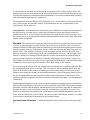
The system computer is a workstation running Microsoft’s Windows NT operating system. The
application program presents a graphical user interface (GUI) on the monitor, interprets input from
the mouse, the knob panel, and the keyboard, and issues the appropriate hardware commands -- via
a local area network -- to the various hardware control interfaces located in the electronics modules.
See “Software Architecture” below for related information
Access to front and
rear of electronics
cabinet
Access to rear of
electronics cabinet
Electronics
Cabinet
(Right)
Swing-away
Vacuum Panel
UI Cabinet
UI Wing
Panel
Front End
Workchamber
Load Lock
Load Port
Module
Facility
Panel
Electronics
Cabinet
(Left)
Service
Monitor
Process Module
Gas Boxes
Gas Box
Doors
Figure 5. Electronic Packaging: Top View
800-000071, Rev. A
26
Principles of Operation
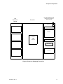
UI Cabinet/Wing Panel
Left
Electronics
Cabinet
Front End
(Right Electronics Cabinet is
behind this panel)
Light Tower
Styrene Gas Box
Alarm Panel
UI Monitor
Br2 Gas Box
Load Port
Module
(AKA
SMIF Pod)
MUI Assembly
XeF2 Gas Box
Video Printer
H2O Gas Box
Control PC
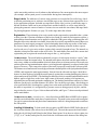
Figure 6. Electronic Packaging: Front View
800-000071, Rev. A
27
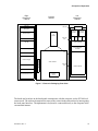
Principles of Operation
Right
Electronics
Cabinet
Left
Electronics
Cabinet
Process
Module
Styrene
Gas Box
Fan Tray
Spicer
FIB Optics
Flood Gun
Controller
Detector Rack
Ion
Column
Br2 Gas
Box
Laser PC
BC 100
Flood Gun
Controller
TMP3 IGP
IGP
Cont. Cont. Cont.
Acht DC Supply
Frozen Bromine
Controller
EOCU DC Supply
XeF2 Gas
Box
Robot Servo DC Supply
UPS
Vacuum Panel
FIB Gun Supply
Work Chamber
H2O Gas
Box
Motion Chassis
UPS Battery
Power Distribution Unit
Facility
Panel
Figure 7. Electronic Packaging: Rear View
The knobs and switches on the knob panel communicate with the computer via the XT100 local
area network. The software determines the states of the various knobs and switches by interrogating
the knob panel interface. The alphanumeric keyboard is connected directly to the computer in the
conventional manner.
800-000071, Rev. A
28
Principles of Operation
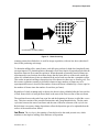
Software Architecture Figure 8 is a conceptual diagram of the layered structure of the FIB
system software. Commands pass downward from the user to the FIB system hardware, and status
information passes upward from the hardware to the user.
The Operating System The foundation for the entire software system is Microsoft’s Windows
NT operating system. The operating system is a collection of software that controls the basic
operation of the computer and that allows the execution of application programs by allocating
memory space, passing information to and from hardware devices, and performing other related
tasks. As an operating system, Windows NT includes device driver programs for operating the
standard peripheral devices with which the computer is supplied (disk units, communications ports,
and so forth). In addition to these device drivers, the FIB system manufacturer augments the
operating system with device drivers for moving information to and from the special hardware
interfaces, such as the vacuum controller, that are unique to the FIB system.
The Application Program At the top of the software structure is the application program,
whose primary function is to present the graphical user interface (GUI) through which the user
operates the system. Refer to the XT100 Program Reference Manual (part number 800-0000XX)
for a description of that program.
Software Design Principles The XT100 software architecture is designed to be extendible,
upgradeable, and easy to maintain. It consists of reusable software components so that changes can
be made without recompiling the entire application and system-level code.
To ensure reusability, the software source code is written using C++, and is COM compliant. A
brief explanation of C++ and COM follows.
C++ is an object-oriented programming (OOP) language that is organized around “objects”
rather than “actions,” and data rather than logic. Historically, a program has been viewed as a logical
procedure that takes input data, processes it, and produces output data. The programming challenge
was seen as how to write the logic, not how to define the data. Object-oriented programming takes
the view that the objects that are manipulated are just as important as the logic required to manipulate
them. Examples of objects range from human beings (described by name, address, etc.) to buildings
and floors (whose properties can be described and managed) down to the little widgets on the
computer desktop (such as buttons and scroll bars).
C++
The first step in OOP is to identify all the objects to be manipulated and how they relate to each
other, an exercise often known as data modeling. After an object has been identified, it can be
generalized it as a class of objects, and defined by the kind of data it contains and any logic sequences
that can manipulate it. Each distinct logic sequence is known as a “method.” A real instance of a
class is called an “object” or, in some environments, an “instance of a class.” The object or class
instance is what runs in the computer. The methods of each instance provide computer instructions,
and the class object characteristics provide relevant data. The user can communicate with objects
- and they can communicate with each other - via well-defined interfaces called “messages.”
The concepts and rules used in object-oriented programming provide these important benefits:
800-000071, Rev. A
29
Principles of Operation
•
The concept of a data class makes it possible to define subclasses of data objects that share
some or all of the main class characteristics. This property of OOP -- known as
“inheritance” -- forces a more thorough data analysis, reduces development time, and
ensures more accurate coding.
•
Since a class defines only the data it needs to be concerned with, when an instance of that
class (an object) is run, the code will not be able to accidentally access other program data.
This characteristic of data hiding provides greater system security and avoids unintended
data corruption.
•
The definition of a class is reusable not only by the program for which it is initially
created, but also by other object-oriented programs (and, for this reason, can be more
easily distributed for use in networks).
•
The concept of data classes allows a programmer to create any new data type that is not
already defined in the language itself.
COM Microsoft’s Component Object Model (COM) is a way for software components to
communicate with each other. COM is a binary and network standard that allows any two
components to communicate regardless of what machine they're running on (as long as the machines
are connected), what operating systems the machines are running (as long as it supports COM), and
what language the components are written in.
A “component” is a building block program that is self-describing. This means that it can be run
with a mix of other components and each will be able to understand the capabilities and
characteristics of the other components. Practically, this means that a new application can be built
by reusing components already known to exist, and without having to compile the application. It
also makes it relatively easy to distribute different components of an application among different
computers in a network. Microsoft's Distributed Component Object Model (DCOM) adds interfaces
to do this.
In addition to its self-description, a component consists of one or more classes that describe objects
and the methods or actions that can be performed on an object. A class (or co-class in COM+
terminology) has properties described in an interface (or co-interface). The class and its interface
are language-neutral.
Associated with the class are one or more methods and fields that are implemented in a specific
language (such as C++ or Java), or in a visual programming environment. When a class is
instantiated, an object (something real that can be executed in the computer) is created. Sometimes
the term “class” is also used for the instantiated object.
Using COM, objects (or classes) and their methods, as well as associated data, are compiled into
binary executable modules. These executables take the form of files with a dynamic link library
(DLL) or EXE file name suffix. A module can contain more than one class.
800-000071, Rev. A
30
Principles of Operation
A DLL is a Dynamic Linked Library - a subprogram initiated by the main program only when
needed to perform a specific task, thereby saving space in memory. For example, as long as a user
of Microsoft Word is editing a document, the printer DLL file does not need to be loaded into RAM
(Random Access Memory). If the user decides to print the document, the Word application causes
the printer DLL file to be loaded and run. DLL files that support the operation of specific devices
are known as device drivers.
DLL
A DLL file is often given a “.dll” file name suffix. DLL files are dynamically linked with the
program that uses them during program execution, rather than being compiled with the main
program. The set of such files (or the DLL) is somewhat comparable to the library routines provided
with programming languages such as C and C++.
User Interface At the top of the software structure is the graphical user interface (GUI) through
which the user operates the system. The UI layer consists of an EXE framework, page controls, and
managers (UI layer managers). Refer to the XT100 Program Reference Manual (part number
800-0000XX) for a description of that program.
The Application Server The objects within the application server provide an interface between
the UI and the hardware server. These objects in this server are built using MS COM, and are
designed to be very generic in the functionality they expose. For example, the Image Analysis
component is designed to expose only generic image analysis functionality, with no XT100
contextual information. The application server contains the following objects:
•
Recipe Page Manager
•
Coordinate Lock Manager
•
Defect Filter Manager
•
Image Analysis Manager
•
Repair Page Manager
•
Chamber Schematic Manager
•
Manual Navigation Manager
•
MUI Controller
•
User Access Manager
The Object Model Layer The Object Model Layer serves as the interface between the
application server and the hardware server. It consists of objects that are implemented as COM
components.
800-000071, Rev. A
31
Principles of Operation
The Hardware Server [The hardware server consists of programs that run more or less
autonomously to maintain continuous control of certain major FIB subsystems. The hardware server
also provides the interface with the XT100 hardware. It consists of the following three layers:
BHV - Behavior layer to control interfaces between subsystems.
·MDL - Model layer to control subsystem behavior;
HAL - Hardware abstraction level to communicate with controllers and actuators (brain and brain
and brawn boards) at each network node (CAN or Ethernet).
800-000071, Rev. A
32
Principles of Operation
FIB System User
GUI (Graphical User Interface)
Application
Server Process
Service GUI
Application Server
(interface between UI layer and Hardware Server)
Object Model Layer (OML)
(high-level control of overall tool behavior)
Behavior Layer (BHV)
(controls interfaces between subsystems)
Hardware
Server Process
Model Layer (MDL)
(controls subsystem behavior)
Hardware Abstraction Layer (HAL)
(communicates with hardware controllers and actuators)
CAN, Ethernet, USB
FIB System Hardware
Figure 8. Software System Organization
All the objects within the hardware server are implemented as “bricks.” Bricks control distinct
software subsystems (programs) within the XT100. These subsystems control specific hardware
components. The behavior layer within the hardware server manages the interaction of the different
subsystems.
800-000071, Rev. A
33
Principles of Operation
A Brick is a Microsoft COM (Component Object Model) component implemented as a DLL. A
DLL is a Dynamic Linked Library - a subprogram initiated by the main program only when needed
to perform a specific task, thereby saving space in memory. A group of Bricks is managed by a
“BrickBox,” and each BrickBox runs in a separate Windows NT process. The configuration of the
distribution of Bricks over BrickBoxes is stored in the Windows NT registry.
The servers accept requests from the application program on behalf of the system user, and operate
the hardware by issuing the appropriate commands to the device drivers. Each server is responsible
for a particular subsystem. For example, the vacuum server communicates with the vacuum
controller—the hardware unit that operates the loading/unloading mechanisms and all of the pumps,
valves, and gauges that are involved in maintaining high vacuum in the workchamber. When the
FIB system user commands the application program to transport a mask holder from the loadport
module, through the air lock chamber known as the loadlock, and onto the moveable stage in the
workchamber (an event referred to as loading), the program sends a load request to the vacuum
server, which sends the appropriate sequence of commands to the vacuum controller to evacuate
the loadlock, to operate the transport mechanism, and to otherwise carry out the loading event.
Other servers include the positioning server, the HV (high-voltage) server, which handles requests
for setting the outputs of the high voltage power supplies and otherwise governs the operation of
the ion column, and the MUI server, which monitors the positions of the knobs and switches on the
manual user interface (also referred to as the knob panel). Refer to page 78 for more information
about the servers.
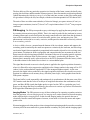
Control and Communications The 100nm XT tool uses a distributed controls
architecture that consists of internal CAN (Controller Area Network) and Ethernet networks. These
local networks are configured in a “star” topology with each station (or “node”) connected to a
central hub, thereby reducing system cabling. Each major electrical subsystem resides on its own
CAN or Ethernet node, and each node has a dedicated processor that allows local decision making
to take place. Because the electrical subsystems are logically isolated from one another, each
subsystem can be upgraded without disrupting the entire system.
800-000071, Rev. A
34
Principles of Operation
CAN - Controller Area Network - a communications protocol
Ethernet - a LAN communications protocol
RS232 - a communications protocol
MUI - Manual User Interface, AKA Knob Panel
Front End - mask loader (load port module, robot)
BC 100 - Beam Control (scan control and acquisition)
Ethernet
Hub
Ethernet
Control
PC
Front End
(Mask
Loader)
Laser
PC
CAN
Detector
Rack
BC 100
USB
CAN
Splitter
CAN
Network
Module
Joystick
Flood
Gun
MUI
(knob panel)
RS232
Robo/Servo DC
Supply
[Work]
Chamber
Robot
RS232
CANRS232
Converter
CAN
System
Module
CAN
Sty Gas
Box
CAN
Network
Module
Br2 Gas
Box
XeF2
Gas Box
H2O
Gas Box
RS-232
CAN
node
Vacuum
Panel
RS232
FIB
HVPS
Figure 9. Communications
The Controller Area Network The majority of the electrical subsystems of the XT100
communicate via a CAN (Controller Area Network).
CAN is based on the so-called broadcast communication mechanism. This broadcast
communication uses a message-oriented transmission protocol. It does not define stations and
station addresses, it only defines messages. Each message is identified with a message identifier.
A message identifier has to be unique within the entire network, and it defines not only the content,
but also the priority of the message. This priority is important when several stations are competing
800-000071, Rev. A
35
Principles of Operation
for bus access. The message with the lowest node ID wins bus access; in the XT100, the PC has
the lowest node ID. Losing nodes keep trying until the bus is available.
A high degree of system and configuration flexibility is achieved as a result of this content-oriented
addressing scheme. It is very easy to add stations to a existing CAN network without making any
hardware or software modifications to the existing stations (as long as the new stations are
receivers). This concept of modular electronics allows multiple reception, as well as the
synchronization of distributed processes. Data required by several stations can be transmitted via
the network, making it unnecessary for each station to know who sent the data. This concept makes
it easier to service or upgrade the network, since data transmission is not based on the availability
of specific types of stations.
Ethernet The remaining electrical subsystems of the XT100 communicate via an Ethernet-based
LAN (local area network).
The XT100 uses a 10Base-T Ethernet, which provides transmission speeds up to 10 Mbps
(Megabytes per second). The Ethernet LAN bus is configured in a “star” topology, with each station
(or “node”) connected to a central multi-port repeater (also known as a hub). All connections in the
network are point-to-point links implemented with unshielded twisted pair (UTP) cables.
Each Ethernet station competes for bus access using the Carrier Sense Multiple Access with
Collision Detection (CSMA/CD) protocol.
The CSMA/CD protocol was originally developed as a means by which two or more stations could
share a common media (cabling type). Each Ethernet station determines for itself when it will be
allowed to send a data frame. The CSMA/CD access rules are summarized by the protocol's
acronym:
•
Carrier Sense—Each station continuously listens for traffic on the medium to determine
when gaps between data frame transmissions occur.
•
Multiple Access—Stations can begin transmitting any time they detect that the network is
quiet (there is no traffic).
•
Collision Detect—If two or more stations in the same CSMA/CD network (collision
domain) begin transmitting at approximately the same time, the bit streams from the
transmitting stations will interfere (collide) with each other, and both transmissions will be
unreadable. If that happens, each transmitting station must be capable of detecting that a
collision has occurred before it has finished sending its frame. Each must stop transmitting
as soon as it has detected the collision and then must wait a quasi-random length of time
(determined by a “back-off” algorithm) before attempting to retransmit the data frame.
USB The Joystick -- which can be used for manual stage movement -- communicates with the
system via the USB (Universal Serial Bus) port on the Windows NT workstation.
800-000071, Rev. A
36
Principles of Operation
The Ion Column The VisION™ ion column generates the ion beam that does the work for
which the FIB system is intended. All of the other system hardware and software serves either to
create a suitable environment for the generation of the beam, or to provide a more or less convenient
means by which it can be put to use. Column performance is generally given in terms of beam
current and spot size. For the mask repair application, the column is operated such that it produces
ion beam currents in the range of 5 to 100 picoamperes and spot sizes from 10 to 40 nanometers.
Figure 10 is a schematic diagram of the ion column. Although simplistically depicted in the
schematic as two-dimensional shapes, most of the elements through which the ions pass are either
hollow cylinders or disks with central orifices. The element stack is aligned so that the geometric
centers of the elements are on a vertical axis called the central axis. Ideally, the stream of ions
passing through the column assumes the shape of a long narrow cylinder whose longitudinal center
corresponds to that central axis. The electrically-active elements that make up the column are
operated electrostatically (by the application of relatively constant voltage), as opposed to
electromagnetically (by the passage of current through them). Note the presence of the gate valve
(VGI) that can be closed by the software to isolate the upper part of the column, including the ion
source and the limiting aperture assembly, from the lower part of the column for servicing (see “Ion
Gun Isolation Valve” on page 58 for related information).
Ion Emission An ion is an atom that has acquired a positive or negative electrical charge by
virtue of losing or gaining electrons, an effect known as ionization. The FIB system uses liquid
metal gallium as the ion source. In the ionization process, gallium atoms usually lose one electron,
thus becoming singly-charged positive ions. Being charged particles, ions can be accelerated and
directed along particular paths by electrostatic fields, and their relatively high mass (compared with
that of subatomic particles) allows them to be used to produce the milling and deposition effects.
Located at the top of the ion column, the ion source has a needle-like tip coated with liquid metal
gallium. A current-regulated power supply heats the source slightly in normal operation to maintain
the liquidity of the gallium. It also allows the source to be heated to a higher-than-normal
temperature when necessary to eliminate impurities and to otherwise condition it for emission.
The source is held at a very high positive potential relative to ground. This potential is called the
acceleration voltage because, when the ions are extracted from the source, it is the force exerted
by this difference in electrical potential that causes them to accelerate through the column to reach
ground potential. The higher the acceleration voltage, the faster the ions are travelling as they exit
the column, and the greater the energy they impart to the specimen. The high-voltage server
normally brings the acceleration voltage gradually to 30 kV when requested by the application
program to power-up the ion column.
Ion emission from the source occurs primarily because of the difference in electrical potential
between the ion source and the nearby extractor electrode. The resultant force draws the liquid
gallium downward into a characteristically pointed shape known as a Taylor Cone, the gallium
atoms at the tip of the cone become excited such that they begin to lose electrons (thus becoming,
by definition, positive ions) and, having assumed a positive charge are drawn from the source to
the extractor. Thus, the extractor voltage is the main determinant of the rate of ion emission. The
800-000071, Rev. A
37
Principles of Operation
high-voltage server attempts to use the lowest extractor voltage that provides a stable rate of
emission.
Although the extractor voltage is the main determinant of ion emission, it is not the only one. Various
phenomena conspire to cause the rate of ion emission to vary slightly over time. To correct for these
0 to 5 A
+
ion source
0 to 2 kV
0 to 30 kV
(acceleration)
+
+
suppressor
0 to 15 kV
-
extractor & spray aperture
lens 1
+
-20 to +20 kV
-
stigmator
(upper octopole)
limiting
apertures
ion gun isolation valve (VGI)
blanking deflectors
blanking aperture
lens 2
+
0 to 30 kV
-
deflection assembly
(lower octopole)
(stage)
Figure 10. Ion Column Architecture.
800-000071, Rev. A
38
Principles of Operation
variations in the interest of providing a constant beam current at the specimen, an element known
as the suppressor is used. Because of its proximity to the source, a relatively small (and therefore
easily controlled) positive potential on the suppressor counteracts the extraction voltage and thereby
reduces the amount of emission.
The regulation technique then, is to set the extractor voltage for more emission than is required,
and to hold the emission at a desired setpoint by dynamically adjusting the suppressor voltage. The
HV server monitors the rate of ion emission and performs this regulation function automatically.
The monitoring technique works as follows: Many of the ions that leave the source follow paths
that do not take them through the annular orifice in the extractor (the spray aperture), but in fact
land on and are absorbed by the extractor electrode and the metal surrounding the orifice in the
spray aperture. Typically, the gallium ions are singly charged (deficient in one electron), and each
ion absorbed by the extractor is neutralized by an electron supplied by the power supply that
develops the extractor voltage. Thus, there is a correlation between the electron current flow in the
extractor circuit—which is relatively easy to meter—and the rate of ion emission from the source.
The current generated in the extractor circuit is known variously as the extractor current and the
extraction current. The HV server program adjusts the suppressor voltage to maintain an extractor
current setpoint, which is typically about 2 microamperes—high enough for a stable supply of ions
that will provide the desired beam current for the work at hand, but low enough for reasonable
source-life. A liquid gallium source operated at 3 microamperes can be expected to provide stable
emission for at least 1000 hours.
A spray aperture is at the bottom of the extractor, and it allows only those ions that are travelling
more or less parallel with, and close to, the central axis to pass. These ions collectively exhibit a
relatively narrow energy spread (they are all travelling at about the same velocity), and therefore
are more suitable for focusing by Lens 1.
Lens 1 Lens 1 is a three-element structure in which each of the elements is operated at a different
electrical potential. The electrostatic field gradients produced by the differences in potential causes
the paths of the ions near the edges of the beam to bend inward toward the center, thereby making
the beam convergent.
The uppermost element of Lens 1 is operated at the same potential as the extractor (which means
that the magnitude of the extraction voltage changes the focusing effect of the lens), and the
lowermost element of Lens 1 is grounded. Assuming that the extraction voltage remains constant,
which is normally the case, it is the potential that is applied to the middle element of the lens that
is increased or decreased to vary the focusing effect of the lens.
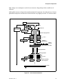
Lens 1 is used to set the beam current by determining the diameter of the beam as it arrives at the
beam-limiting aperture element. If the diameter to which the lens focuses the beam is equal to or
less than the diameter of the beam-limiting aperture, the current density—the number of ions per
unit area that pass through the aperture—is maximum. If Lens 1 is used to defocus the beam so that
its diameter exceeds the size of the aperture, the current density downstream from the aperture is
diminished. Figure 11 illustrates the principle.
800-000071, Rev. A
39
Principles of Operation
Same
Limiting
Aperture
(a) Lens 1 focused for high
current density.
(b) Lens 1 focused for lower
current density.
Figure 11. The Effect of Lens 1 on Current Density.
Beam-Limiting Apertures A beam-limiting aperture is any of 14 apertures that are arranged
in two parallel lines on a horizontal sliding bar and that can be brought into position by a mechanical
drive mechanism. Homing the positioning mechanism withdraws the sliding bar completely so that
the beam is unrestricted; this is normally done only when servicing the column.
A beam-limiting aperture reduces the beam diameter at the point of interception, and has a
proportional effect on the spot size—the smallest spot to which Lens 2 can focus the beam on the
specimen. The combination of the size of the beam-limiting aperture and the current density
established by the focusing of Lens 1 is the major determinant of beam current delivered by the
column and, to a lesser degree, of spot size (the spot size increases somewhat with the current
density).
The standard set of beam-limiting apertures installed on Accura 850 systems consists of six 25-µm,
apertures, two 30-µm apertures, four 40-µm apertures, and two 60-µm apertures. The 25-µm aperture
size is expected to be used most often because it yields a combination of spot size (20 to 30 nm)
and beam current (10 to 20 pA) that is typically preferred for mask repair. An aperture eventually
deteriorates with use—the orifice becomes enlarged by the ion beam; hence the need for
redundancy. While the ion column remains powered up, the currently-selected beam-limiting
aperture remains in the path of the beam and is eroded by it. To extend the useful life of the aperture
set, a “sacrificial” aperture should be selected (“parked” in the beam path) if the ion column is to
remain powered up but idle for any appreciable time. The sacrificial aperture would be one of the
little-used apertures (e.g., 60-µm), or any aperture that has already deteriorated beyond use.
800-000071, Rev. A
40
Principles of Operation
The Lens 1 focus voltage that produces the highest current density (irrespective of spot size), for
each of the beam-limiting apertures is one of several items of data specified in a data structure called
a lens table, and is asserted by the software when it positions a particular aperture for use. The
amount of stigmation force that is required also tends to vary with the beam’s diameter and current
density, which means that selecting a beam-limiting aperture of a different size usually requires
re-stigmating the beam. Therefore, the software also saves stigmation values in association with
each of the beam-limiting apertures in the lens table. See “Stigmation” below.
When it is desirable to alter the current density or (to a much lesser degree) the spot size for a given
beam-limiting aperture, a virtual aperture can be implemented through the application software.
When the user selects a virtual aperture, a specified hardware aperture is selected, but the software
sets the Lens 1 focus voltage according to an alternate lens table.
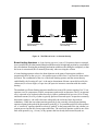
Stigmation The upper octopole, also known as the stigmator, is used to introduce correction for
astigmatism, which is the failure of the column to make the ions converge uniformly to a circular
spot. Astigmatism can be expected to develop as the beam enters Lens 1 because, despite the
passively collimating effect of the spray aperture (see above), not all the ions entering the lens will
be on parallel paths, nor will they be evenly distributed about the central axis. The focusing effect
of the lens is therefore not uniformly applied, and the ions do not become uniformly convergent.
Figure 12 (a) attempts to illustrate the nature of the problem by representing the beam as having
become elliptical in cross section (instead of circular) as it emerges from Lens 1, the result of having
become more convergent in y than in x. Note that the dots representing the ion paths are not evenly
distributed. Thus, the problem is not simply a matter of the cross-sectional shape of the beam being
non-circular (which could be corrected by a limiting aperture), but involves the spacing of individual
ion paths, and Lens 2 would be expected to amplify the effect.
The stigmator consists of eight radially-oriented electrostatic deflection elements. Voltages of equal
magnitude and polarity are applied to opposite elements so as to produce opposing forces that tend
to reshape and collimate the beam. Figure 12 (b) attempts to illustrate this effect, and Figure 12 (c)
attempts to illustrate the result. The stigmator is used empirically to obtain the most sharply focused
spot for the column as a whole, and its correction therefore represents some combination of undoing
the astigmatic effect of Lens 1 and anticipating the astigmatic effect of Lens 2.
Minor differences in the forces exerted by a given voltage on opposite poles of the stigmator (due
to manufacturing tolerances) are corrected by introducing voltage offsets through a service
procedure known as the quad balance calibration.
Because the stigmator is located above the beam-limiting aperture, it can also used to deflect the
beam slightly to center it on the aperture, an effect that is known variously as fine align, upper shift,
and beam align.
Blanking Given the amount of electrical power that is required to produce ion emission, and the
complexity of maintaining stable emission, the ion beam cannot be rapidly switched on and off at
the source. Instead, the combination of the blanking deflectors and the blanking aperture is used
to achieve this switching effect as follows.
800-000071, Rev. A
41
Principles of Operation
(a) cross-sectional representation of the
beam before stigmation
(b) corrective forces exerted by the stigmator
(c) astigmatism reduced
Figure 12. Stigmation.
With no potential applied to the blanking deflectors, the beam passes undisturbed through a large
orifice in the blanking aperture element. This is the unblanked state. When voltages of opposite
polarities are applied to the blanking deflectors, the beam ions, being positively charged, are repelled
by the positive deflector and attracted by the negative deflector, the net effect being that the beam
misses the orifice and is absorbed by the aperture element. This effect is known as blanking the
beam. When the column is powered up, but not in actual use, the beam is blanked.
The amount of beam current that the column is delivering to the mask is an important factor in the
milling and deposition processes. The blanking aperture element provides one means of measuring
the beam current in the column downstream from Lens 1 and the beam-limiting aperture. The
blanking aperture element is connected to electrical ground through a DC metering circuit. While
the beam is blanked, the potential created by the arrival of positive ions draws electron current from
ground through this metering circuit. The beam current can also be measured with the ion faraday;
see page 53.
When the beam is deflected onto the blanking aperture by the blanking elements, it does not
instantaneously disappear—it moves out of the normal scan field and into occultation. Although
its motion is very rapid, it still delivers a finite ion dose along the way. Depending upon the
application, this may result in a cumulative effect known as blanking tails. See “Rastering” below
for related information.
800-000071, Rev. A
42
Principles of Operation
Lens 2 Whereas Lens 1 is used to adjust the beam current density, Lens 2 is used to focus the
beam on the specimen. This is the lens that the user controls with the Focus knob on the knob panel
(or the software presets). Lens 2 applies the same principle as Lens 1 to cause the ions to converge
as they travel toward the focal plane—the plane in which the ion trajectories cross and therefore
the plane in which the spot size is smallest.
The Deflection Assembly The deflection assembly includes an octopole that is similar to the
stigmator, but is operated differently. In the stigmator, opposing pairs of deflectors are used to exert
lateral “push-push” or “pull-pull” forces on the beam as necessary to correct for astigmatism. Once
the appropriate combination of correctional voltages is established, it can be maintained until some
event that changes the beam’s astigmatism occurs. In the deflection assembly, opposing pairs of
deflectors are used dynamically to exert lateral “push-pull” forces to deflect the beam from the
central axis. Thus, they work somewhat like the blanking deflectors except that, with four pairs of
deflectors, the beam can be placed at any point within the range of deflection. Also, whereas the
voltage applied to a blanking deflector is either zero or some predetermined fixed value, the voltages
applied to a deflection assembly are scaled according to where the beam is to be placed. During
imaging, milling, or deposition, the ion beam is deflected back and forth along a series of parallel
paths in what is called a raster pattern (see “Rastering” below). To achieve this, various
combinations of ramped voltages are applied to the deflection assembly to move the beam along
the appropriate paths.
Typically, the area that a raster has to cover is smaller than the deflector’s maximum scan range.
When this is the case, the raster-producing scan signals that are applied to the deflector can be
biased so that they offset the center of the raster from the center of the deflection range, an effect
known as panning. The pan knobs on the knob panel allow the user to pan the scan field when
imaging with small fields of view, and the application software also uses the panning effect to
correct for stage-positioning error when it brings work sites on the mask under the ion column.
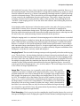
Rastering Rastering means scanning the beam such that it traces a pattern of closely-spaced
parallel lines as shown in Figure 13. One iteration of this raster scanning pattern is called a frame.
It is also referred to as a raster (refer to the Glossary for further discussion of raster). Each of the
scan lines constituting the raster scanning pattern is in fact a linear array of discrete points to which
the beam is rapidly deflected and at which it pauses or dwells for a predetermined period. These
points are called dwell points, and the time for which the beam dwells at each dwell point is called
the dwell time. The dwell point spacing, also called DAC spacing, is the distance between the centers
of adjacent points.
Raster scanning is used for milling, deposition, and imaging. Two raster scanning schemes are
implemented: normal and serpentine. In normal raster scanning, the beam proceeds along each scan
line in the same direction. It is blanked (see page 41) at the end of each scan line while the deflection
electronics are directed to place it at the opposite end of the next scan line. It is then unblanked,
and deflection proceeds. Except for multiplex imaging rasters, the beam is not blanked between
dwell points (multiplex imaging is explained under “Imaging Modes” on page 45). The act of
redirecting the beam from the end of one scan line to the opposite end of the next scan line is called
retrace. Serpentine scanning involves reversing the scan direction on alternate scan lines, thus
eliminating retrace and the need to blank the beam while it is taking place. The normal raster
800-000071, Rev. A
43
Principles of Operation
dwell points
dwell point spacing
frame
(one iteration of raster pattern)
Figure 13. Raster Scanning.
scanning pattern described above is used for image acquisition, with one low-dose (short dwell
time) frame producing each image.
To obtain the milling effect, many frames, each delivering a relatively high dose (long dwell time),
are superimposed. To obtain deposition, thousands of low-dose frames are superimposed while the
deposition chemical flows onto the specimen. When thousands of normally-rastered frames are
superimposed in one location, the minute dosage that the beam delivers to the mask outside the
raster as it is blanked (travels into occultation) at the end of each scan line has a cumulative effect.
This results in spurious milling or deposition, an effect known in either case as blanking tails. For
this reason, serpentine scanning is preferable whenever large numbers of frames are to be
superimposed because it decreases the number of times the beam is blanked (by a factor equal to
the number of frames times the number of scan lines per frame).
Regardless of which scanning mode is chosen, the beam is always blanked after the last scan line
of each frame while it is being deflected back to the start of the first scan line of the next frame.
The total time between the end of one scan line and the beginning of the next is called the retrace
time. This time consists of the actual deflection time and a programmable delay. The the entire
cycle time between the start of one frame and the start of the next is known as the refresh time.
Refresh time is necessary during deposition to allow the deposition gas to be replenished on the
surface of the mask between frames.
Ion Dose The ion dose is the quantity of ions delivered to the mask per unit area, which
translates to the depth of milling or the thickness of deposition.
800-000071, Rev. A
44
Principles of Operation
The dose delivered for any particular operation is a function of the beam current, the dwell point
spacing, the dwell time, and the number of frames (rasters). Dose does not take acceleration potential
(which determines the velocity or energy level of the ions) into account, so the effect on the mask
of a given dose is likely to be less, for example, with the acceleration potential at 25 kV than at 30 kV.
The units of dose are either nanocoulombs (of electrical charge) per square micron (nC/µm2), or
ions per square centimeter (ions/cm2). One nC/µm2 is equivalent to about 6.25 x 10¹⁷ ions per square
centimeter.
FIB Imaging The FIB system produces gray-scale images by applying the same principles used
by scanning electron microscopes (SEMs). That is, the mask is probed by the ion beam in a raster
scanning pattern and, at each dwell point, the energy transferred to the mask from the decelerated
ions excites it and thereby causes it to emit electrons, positive ions, and negative ions. This
phenomenon is referred to as secondary emission, and the particles emitted are collectively referred
to as secondary particles.
A device called a detector, mounted near the bottom of the ion column, attracts and captures the
secondary particles emitted by the mask in response to excitation by the ion beam, and it develops
an electrical signal whose magnitude is proportional to the number of particles it is receiving at any
given instant. Variations in surface topography and composition that are encountered as the ion
beam scans the object being imaged produce variations in the rate of secondary particle emission,
which result in variations in the electron current—the signal—produced by the detector. The
detector that is normally used is often referred to as the MCP (pronounced like the letters), which
is the abbreviation for the kind of device that it is: a microchannel plate.
The signal thus detected at successive dwell points is applied to the signal acquisition electronics,
where it is filtered for noise-suppression, and digitized to a binary number in the range of 0 to 255
(where 0 is the weakest/darkest signal and 255 is the strongest/brightest signal). As the scan
proceeds, the digital values produced by the signal acquisition electronics are stored in successive
locations in a random access memory array, called the frame buffer, in the graphics board in the
FIB system computer.
The frame buffer is read sequentially and continuously in synchronism with the raster scan of the
CRT monitor such that the value of each byte of image data determines the combination of red,
green, and blue (RGB) signals that lights one dot or pixel on the CRT to a particular gray level.
However, the image data may be translated by the software in various ways before it becomes the
RGB signal that illuminates pixels on the CRT.
Imaging Modes The FIB system uses any of three techniques for capturing secondary emission
from the specimen: electron imaging mode, ion imaging mode, and a variation of electron imaging
mode called multiplex imaging mode. In the electron imaging modes, the particle detector is
electrically biased to attract and capture electrons; in ion mode it is biased to attract and capture
positive ions.
Electron imaging mode often produces clearer images than ion imaging mode because the secondary
electron yield from most materials is greater than the secondary ion yield, and the imaging signal
800-000071, Rev. A
45
Principles of Operation
also tends to be less noisy. Also, a lower ion dose can be used for image acquisition. However, if
the area being imaged is electrically nonconductive, being either an insulator (e.g. quartz) or a small
island of conductive material (e.g. chrome) surrounded by insulating material, it quickly develops
a positive electrostatic charge. This is due to the loss of electrons through secondary emission and,
to some extent, by the implantation of positive gallium ions. This positive charge can prevent
secondary electrons from escaping from the surface of the specimen, thus rendering the mask
“invisible” to the imaging process. It can also deflect the ion beam, thus affecting the placement
accuracy of repairs.
In ion imaging mode, the detector is biased to attract positive ions, and a flood gun (see below),
which directs a stream of free electrons at the specimen, can therefore be employed for
positive-charge neutralization during rasters. The flood gun cannot be used while the detector is
biased to capture electrons because the electron flood would saturate the detector, reducing its useful
life and, in any case, totally obscuring electron emission from the specimen.
Multiplex imaging mode is a variation of electron imaging mode in which the detector is switched
off, and the flood gun is switched on, during the time that the ion beam is moving between dwell
points. While the beam is dwelling at any particular point, the flood gun is switched off and the
detector is switched on. This has the advantages of both electron and ion modes: clearer images
with concurrent charge neutralization. However, it requires significantly more time to produce an
image than the other modes and, to be effective, it requires relatively frequent recalibration of the
flood gun to verify that it is correctly aimed and energized.
Imaging Speed The rate at which an image raster proceeds is generally referred to as the imaging
speed. The dwell time—the time during which the ion beam is directed at each dwell point—is the
main determinant of the imaging speed for ion mode or electron mode. For these imaging modes,
the retrace time is the same, and the transition time between dwell points is negligible. However,
for multiplex imaging mode, the transition time between dwell points and the retrace time are
extended to allow charge neutralization and therefore become significant factors. Accura 850
systems provide three imaging speeds—slow, medium, and fast. The overall image size (see below)
is also a factor in image acquisition time.
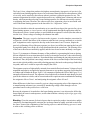
Image Size The term image size is generally used in reference to the area of the
2562
computer screen that is occupied by the image produced by a raster. The application
program enables the user to select (through an array of graphics such as those shown
5122
here at right) four progressively larger image sizes ranging from 256 by 256 to 1024
by 1024. The numbers refer to the number of pixels on the computer screen (hence
7682
image size), as well as to the number of dwell points in the image rasters that produce
the images (there is a one-to-one correspondence). The numbers are not related to the
10242
dimensions of the area being scanned to produce the image, which is determined by
the field of view selection. However, they do relate to resolution: the larger the image
size selected for a given field of view, the greater the dwell point density, and therefore the greater
the resolution (and apparent magnification).
Pixel Averaging Pixel averaging involves sampling the signal from the detector for a series of
short periods during the dwell, averaging the signal levels thus obtained, and digitizing that average
800-000071, Rev. A
46
Principles of Operation
as the information for the dwell point. The principle is that, when the signal produced by the particle
detector as a result of the impingement of the ion beam at a given dwell point is sampled repeatedly,
and is averaged over the number of samples, the randomly-occurring information (“noise”) will
eventually constitute a relatively small part of the final result, while the valid information will tend
to prevail. The duty cycle for the sampling electronics is chosen by the software based upon the
dwell time.
The Flood Gun The flood gun is an electron-emitting device that is suspended horizontally
near the lower end of the ion column to direct a beam of low-energy electrons at the mask in an
area roughly corresponding to the field of view. This electron flood neutralizes the positive
electrostatic charge that tends to build up on the mask during rastering. Electrostatic charge buildup
interferes with imaging, and may result in electrostatic discharge that damages the specimen. See
“Imaging Modes” on page 45 for related information.
The application program’s Power Up function powers up the flood gun as well as the ion column.
While it is powered up, the flood gun operates continuously as long as the selected imaging mode
is ion. It is operated intermittently during imaging rasters while the imaging mode is multiplex, and
it is blanked (its emission suppressed) while the imaging mode is electron. Thus, in general, the
operation of the flood gun is automatic and operator intervention is not required. (Although, if the
user images a mask in electron mode or multiplex mode, and then proceeds with milling or
deposition without switching to ion imaging mode, the flood gun will remain blanked and no charge
neutralization will take place. Depending upon the circumstances, this may or may not be desirable.)
The flood gun assembly consists of an electron gun and a cylindrical structure, sometimes called
the snout, which incorporates an electrostatic lens and a vertical deflection element. The electron
gun itself comprises several electrodes (refer to Figure 14):
•
Filament: a cathodic electrode consisting of either a small tungsten disk or a short length
of tungsten wire. A direct current (the filament current) is passed through it to produce
thermionic emission of electrons. The power supply that is the source of the filament
current is floated on (biased by) a negative potential produced by a power supply, called
the cathode supply, such that the filament itself is negative with respect to ground. The
electron current that flows from this cathode supply to ground is called the cathode
current, and it serves as a measure of the output of the gun.
•
Anode: Electrons emitted by the filament are accelerated toward and exit through a
grounded annular anode at the opposite end of the gun.
•
Grid: This is a wire-mesh electrode interposed between the filament and the anode. A
negative potential can be switched onto the grid to counteract the acceleration potential
between the filament and the anode, and the gun can thereby be blanked (shut off) while
preserving a state of filament-readiness.
The electrons pass through the anode and into the snout, where they are directed such that, when
they exit the snout and enter the electrostatic field produced by the various potentials on the particle
detector, they assume trajectories that takes them to the appropriate area on the specimen.
800-000071, Rev. A
47
Principles of Operation
detector screen
grid
annular
anode
heated cathode
(filament)
e-
e-
deflectors
grid
supply
filament
supply
cathode
supply
+
Figure 14. Schematic Diagram of Flood Gun.
The Funnel The funnel is a shallow pan-shaped metal structure that is suspended below the
ion beam column, primarily for the purpose of providing an electrostatic shield between the electron
flood and whatever static electric charges may be present on the mask. An orifice in the center of
the pan allows the ion beam and the electron flood to pass through to the mask while the funnel
itself provides a relatively large grounded plane. A vertical motion mechanism is provided that
extends (lowers) the funnel to a position close to the mask to maximize its effectiveness during
charge neutralization, and that retracts (raises) it slightly to provide vertical clearance for
maneuvering the stage in the x-y plane.
The funnel also serves as a mount for the carbon deposition gas delivery nozzle, as well as for the
delivery nozzles for any other chemicals that may be installed in the system.
The Stage The ion column is stationary, and its field of view (scan field) is relatively small.
Therefore, a moveable stage is incorporated to allow the mask to travel about in the x-y plane to
bring points of interest under the column. The stage is implemented with piezoelectric linear drive
mechanisms as depicted by Figure 15. Working travel is ±4 inches (±100 mm) from center, which
accommodates masks up to 7 inches (200 mm) square, and allows diagnostic fixtures (see below)
on the stage to be positioned under the column.
800-000071, Rev. A
48
Principles of Operation
ion
column
stage zero
position
y travel
x travel
load/unload
path
loadlock
Figure 15. X-Y Stage Motion.
Positioning Server [A software program known as the positioning server operates the stage at
the hardware server level. It maintains an awareness of the position of the stage, and processes
requests for stage motion by application programs.
Stage Motion Controls The FIB system user can move the stage with a joystick, or with a
variety of controls provided by the application software. The joystick operates the stage directly
through the computer’s USB port (using DirectX drivers); other controls operate by requesting
actions through the stage positioning server. Stage motion for the purpose of positioning defect
sites on the mask under the ion column is normally controlled by the application software (through
the positioning server) based upon inspection data provided for the mask.
Stage Zero The stage’s position (or address) is registered by hardware counters as its
displacement in x and in y from mechanical switches that define the right-rear limit of its travel (see
Figure 15). Thus, the stage’s position address increases as it moves away from this reference position
and decreases as it moves toward it. The reference position is referred to as Stage Zero. The stage
800-000071, Rev. A
49
Principles of Operation
can be sent to this position (zeroed) whenever the indication of its current position becomes suspect
(for example, when system power is restored after having been interrupted).
Stage Labels The addresses of various stage positions are recorded in files called stage labels
so that the positioning server software can send the stage to any of them when requested to do so
by the application program. Included are stage labels for the load position (in which the stage is
docked such that a mask can be moved between it and the loadlock) as well as stage labels for
placing the geometric centers of masks of various sizes are under the ion column, and stage labels
for placing diagnostic fixtures (see page 52) on the stage under the column.
Registration The positioning of successive masks on the stage must be repeatable in the x-y plane
so that, given the Cartesian coordinates of defect sites found on a mask by an inspection system, a
predetermined transformation can be applied to obtain the FIB system stage coordinates that will
bring the defect sites under the ion column. It must also be vertically repeatable because FIB process
parameters for mask repair presuppose a fixed relationship between the top surface of the mask,
the electron funnel, and the ion column. The repeatable positioning of masks in these respects
involves the use of registration surfaces against which a mask is brought to bear. The internal (or
chamber) robot places the mask on the mask holder. The mask holder uses small drive motors and
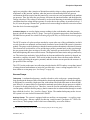
registration pins to register the mask on the stage in the x, y, and z planes.
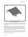
The mask holder mechanically accepts a 6-inch square mask (or “reticle”) that
is transferred from the internal robot. The internal robot places the mask onto the mask holder to
an accuracy within several thousandths of an inch, then retracts to its home position. The mask rests
on three spherical registration buttons whose z-axis height and coplanarity are aligned with a high
degree of accuracy. This ensures the surface of the mask is properly located in the reference plane.
The buttons are manufactured from a high performance thermoplastic called polyetheretherketone
(PEEK), and support the mask approximately 2mm in from the side and rear edges. Small drive
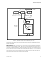
motors are then employed to bank the mask squarely against three rotating banking pins (that are
also manufactured from PEEK). The banking mechanism (which is mounted underneath the mask
holder) applies a light force to the lower right corner of the mask, pushing it left against two
alignment pins and forward against the remaining pin. The banking mechanism consists of a 12mm
diameter cam driven by an 8mm diameter DC motor. The cam directs a pivoting v-block riding on
a low profile ball slide, which applies a spring force to the mask and holds it firmly in place. When
the mask is in position, it is recognized by a presence sensor as being properly in place, and the
stage is then free to move. Figure 16 shows the mask holder, and Figure 17 shows a mask positioned
on the mask holder.
The Mask Holder
A mask carrier -- also referred to as an RSP (Reticle SMIF Pod) is a square,
pan-like carrier that holds a mask plate of a particular size. The mask carrier protects the mask plate
(or reticle) against abrasion and particulate contamination while it is being transported to and from
the FIB system.
The Mask Carrier (RSP)
Loading & Unloading To load a mask, the user places an RSP (Reticle SMIF Pod) at the top of
the Load Port Module (also referred to as the SMIF pod). The user then opens the Load/Unload
dialog box by clicking Load/Unload on the [Menu Name] menu. Next, the user selects a plate size
[???](5, 6, or 7 inches) and a plate file, then clicks the Load button at the bottom of the dialog box.
800-000071, Rev. A
50
Principles of Operation
y-axis mask-registration
surface
x-y motor / z motor / actuator / cam / registration pins / etc.
x-axis & z-axis mask registration surfaces
z-axis registration clamp
release pressure points
Figure 16. The Mask Holder
800-000071, Rev. A
51
Principles of Operation
Figure 17. Mask Holder with Mask in Place
[See Figure 18 -- Mask Carrier (RSP)] An automated loading system -- involving two transfer robots
and automated alignment mechanisms -- transfers the mask to the positioning stage. When imaging
and repair procedures are complete, the mask is automatically returned to its mask carrier in the
load port module.
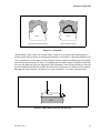
Diagnostic Fixtures Refer to Figure 19. Several devices that are used for alignment and
calibration are mounted near the rear edge of the stage. These include the silicon grid, the ion
faraday, and the electron faraday. The stage position that places each of these devices under the
ion column is recorded on disk as a stage label file so that the software can bring them into play
whenever necessary. A solid state sensor for gauging workchamber temperature is also mounted
on the worktable. The other devices are explained below.
The silicon grid is a flat silicon chip, about 10 mm by 16 mm, on which is etched
a grid of 5-micron lines on 35-micron centers. It is used as an imaging target for various system
alignments. When the mask plate is registered on the stage, its top surface is in the same horizontal
plane as the top surface of the silicon grid.
The Silicon Grid
800-000071, Rev. A
52
Principles of Operation
Photograph of Mask Carrier
(my nomenclature for the RSP, or Reticle SMIF Pod, which
protects the mask plate (reticle) against abrasion and particulate
contamination while it is being transported to and from the FIB system).
Figure 18. The Mask Carrier
The ion faraday is a small cup-like structure used to measure the ion beam current
being delivered by the column. It provides an alternative to using the beam blanking aperture
element (page 41) to measure the beam current. Also, the ion faraday has across its opening a metal
grid structure that serves as a convenient imaging target for performing various alignment tasks
such as stigmation. The grid is about 3 mm in diameter, the bars in the grid are roughly 30 to 50
microns wide, and the spaces between the bars are about 110 to 135 microns wide.
The Ion Faraday
To measure the beam current with the ion faraday, the stage is positioned so the beam can be directed
through an opening in the grid and onto the floor of the cup. The cup is connected to electrical
ground through an electron current metering circuit in essentially the same manner as is the blanking
aperture.
The ion faraday cup may provide a slightly more accurate measure of beam current than the beam
blanking aperture element because the walls of the cup usually capture all of the secondary particles
that are emitted in the cup as a result of ion bombardment. Although a set of elements is installed
800-000071, Rev. A
53
Principles of Operation
silicon grid
ion faraday
electron faraday
temperature sensor
Figure 19. Diagnostic Fixtures on the Stage.
in the column in proximity to the beam blanking aperture element to suppress secondary electron
emission while trapping positive secondaries, some electrons or other negative particles may still
escape to other parts of the column, thus drawing extra electron current through the metering circuit
and yielding beam current readings that are slightly high.[3] However, in general, the blanking
aperture is a preferable metering point for beam current because obtaining a reading does not require
the stage to be repositioned.
The electron faraday measures the electron output from the flood gun. It is
physically and operationally similar to the ion faraday (see above), but it measures electron current
from the cup to electrical ground instead of vice versa, and it does not have the grid structure across
its opening.
The Electron Faraday
Stage Position Tracking The piezoelectric drive motors for the FIB system’s stage can position
the stage to within 100 nanometers of an x-y address called for by the software. Thus, when the
software calls for a particular point on the mask to be brought directly under the center line of the
[3] For the same reason, it is essential that, when a faraday reading is taken, the stage be positioned so that the beam
passes through an opening in the grid. If it strikes any part of the grid, a significant amount of secondary electron
emission from the affected area will escape upward, thereby causing an erroneously high reading.
800-000071, Rev. A
54
Principles of Operation
ion beam column, that point may in fact be as far as 100 nanometers from the center line on either
or both axes when the stage comes to rest. The software can compensate for this position error by,
in effect, moving the ion beam column’s scan field off-center, but it must know what the error is.
This information is provided by laser interferometers or linear encoders for each axis.
Interferometry
Refer to Figure 20, which illustrates how interferometry works on one axis. Simply
ion column
reflector 2
stage
reflector 1
axis drive
motor
interferometer
mechanical power
transmission
1 pulse = 100 nm
1 pulse = 5 nm
Figure 20. Stage Position Tracking.
put, the interferometer directs a laser beam along the axis to a mirror mounted on the side of the
stage (reflector 1), and compares the wave length of the reflected light with that of the transmitted
light. While the stage is moving along the axis toward the interferometer, the phenomenon known
as the Doppler effect causes the wave length of the reflected light to appear shorter than the wave
length of the transmitted light. Conversely, while the stage is moving away from the interferometer,
the apparent wave length of the reflected light appears longer than that of the transmitted light.
Interference patterns resulting when the two light beams are combined provide detectable pulses
that can be directly correlated with distance moved.
The digital counters that register stage position are reset to zero when the stage is at the Stage Zero
reference position, and then are incremented by pulses produced by the interferometers as the stage
moves away from the reference position, and decremented as it moves back.
800-000071, Rev. A
55
Principles of Operation
A reference mirror mounted in a fixed position in proximity to the ion beam column allows the
interferometer to detect and compensate for relative motion between itself and the stage that results
from thermal expansion or contraction of the workchamber. The net effect is that the interferometers
indicate motion in increments of 5 nanometers.
The arrangement illustrated in Figure 20 is duplicated, at 90°, for the other axis. The mirror for each
axis is wide enough, and carefully aligned, so that motion on one axis is undetectable by the
interferometer for the other axis.
Linear Encoders If an interferometer indicates an error condition (for example, an interruption of
the laser beam by a foreign object), stage motion feedback to operate the position counters is
available from linear encoders that are incorporated in the stage piezoelectric drive motors. As a
drive motor moves, its encoder produces digital pulses that indicate displacement, from which stage
motion can be extrapolated.
Vacuum The ion beam can be generated only in an extremely low-pressure environment, which
is to say, an enclosed space as nearly devoid of gas molecules as is feasible. This is because the
intense electrostatic fields in the column will ionize any gas molecules that might be present. Ionized
particles conduct electricity if the particle density is such that electrons can jump from particle to
particle. Thus, if the column is powered-up with enough gas present, electrical arcs will occur
between electrodes, electrode vaporization and ion implantation will occur, and the column will
thereby be damaged or destroyed. Ionized particles are also accelerated to electrodes having an
opposing charge, where they accumulate, eventually affecting the operation of the column. For
these reasons, as well as for the safety of service personnel, the FIB system is interlocked such that
an abnormal rise in internal pressure switches off the high voltage to the column.
The need to keep the interior of the ion column evacuated when power is applied to it dictates that
the workchamber must also be evacuated. This is because the opening through which the beam
passes at the bottom of the column will admit gas molecules and, in any case, the beam would
dissipate after exiting the column if it encountered atmosphere. Also, the imaging scheme involves
the use of a particle detector that is mounted on the outside of the bottom of the column. If the
operating voltages are applied to this detector while it is exposed to atmosphere, it can be damaged
or destroyed.
Maintaining an adequately low gas pressure requires continuous pumping because gas molecules
drift into the evacuated spaces from various sources within the system itself. These sources include
lubricants, electrical cable insulation, and atmospheric gases and water vapor that are adsorbed by
the interior surfaces of the workchamber when the workchamber is opened for servicing. Also,
whenever a mask plate is brought into the workchamber, some adsorbed atmospheric gases and
water vapor inevitably enter with it. Finally, the pressure in the workchamber normally rises when
a process gas is introduced for deposition or gas-assisted etching.
Vacuum System Schematic A schematic diagram for the vacuum system is shown in Figure
21.
800-000071, Rev. A
56
Principles of Operation
N2
Gas Cabinets
V31
Source
Check
Valve
N2
V34
V32
N.O. valve
opens when TMP3 is off
FIB
Column
GRVi
V35
TMP3
IGPig
V33
BT3
Styrene
N2
GlVi
V41
Source
PVP3
Check
Valve
GVVi
LLPG
IGPic
BPVi
LLVS
V44
V42
CLV
V45
V36
V46
Loadlock
V66
V43
BT4
LLVS
V56
Br2
Funnel
LLIV
V61
Check
Valve
Chamber
V64
V62
TMP1
WRG
LLV V
TMP2
V65
CVV
V63
BT6
V51
XeF2
Check
Valve
Purge
inlet
PVP1
CRV
LLBV
LLRV
LLSRV
FLPG
V54
V52
V53
V55
BT5
H2O
Pumps
IGPig -- Ion Getter Pump, FIB Gun
IGPic -- Ion Getter Pump, FIB Column
PVP1 -- Pre Vacuum Pump, Chamber
PVP2 -- Pre Vacuum Pump, Loadlock
PVP3 -- Pre Vacuum Pump, FIB Gun
TMP1 -- Turbo Molecular Pump, Chamber
TMP2 -- Turbo Molecular Pump, Loadlock
TMP3 -- Turbo Molecular Pump, FIB gun
PVP2
RLPG
Gauges
RLPG -- Pirani Vacuum Gauge, Roughing
RLPG -- Pirani Vacuum Gauge, Loadlock
CHPG -- Pirani Vacuum Gauge, Chamber (not used)
FLPG -- Pirani Vacuum Gauge, TMP1
WRG -- Wide Range Gauge
HCIG -- Hot Cathode Ion Gauge (not used)
CCIG -- Cold Cathode Ion Gauge (not used)
BTx -- Chemical Cabinet Baratron Gauge
Sensors
LLVS -- Loadlock Vent Sensor
Valves
GIVi -- Gun Isolation Valve, FIB
GV Vi -- Gun Vent Valve, FIB
GRVi -- Gun Roughing Valve, FIB gun
BPVi -- By Pass Valve, FIB column
CIVi -- Column Isolation Valve, FIB (not used)
CLV -- Chamber Load Valve
CRV -- Chamber Roughing Valve
CV V -- Chamber Vent Valve
TPV -- Turbo Purge Valve (not used)
LLV -- Loadlock Load Valve
LLIV -- Loadlock Isolation Valve
LLV V -- Loadlock Vent Valve
LLSRV -- Loadlock Soft Roughing Valve
LLRV -- Loadlock Roughing Valve
LLBV -- Loadlock Backing Valve
Vx1 - 6 -- Chemical Cabinet Valves
Figure 21. Vacuum System Schematic.
The Loadlock The loadlock is an air lock that allows the mask to enter and leave the
workchamber without requiring the workchamber to be completely vented and re-pumped. The
loadlock opens to atmosphere through an outer door called the loadlock door, and it opens to the
workchamber through a wide vertically-operating gate valve called the chamber door (CLV in
Figure 21).
Venting To minimize adsorption of atmospheric gases when any part of the vacuum system must
be vented to atmospheric pressure, nitrogen gas (N2) is admitted to equalize the internal and external
800-000071, Rev. A
57
Principles of Operation
pressures. This occurs, for example, whenever the loadlock is vented to atmospheric pressure at the
end of the unloading sequence.
Vacuum Server/Controller A software program known as the vacuum server runs in the system
computer concurrently with the application program (and other servers). It maintains an awareness
of the status of the vacuum system, and it processes requests for vacuum actions by the application
program. This involves translating high-level requests (for example: “load a mask plate”) to the
actual sequence of low-level commands involved in carrying out the request (for example: “open
valve V1,” “open valve V4,” etc.). The vacuum server sends the low-level commands through a
communications link to a continuously-running firmware program that is stored in read-only
memory in a hardware device called the vacuum controller. The program in the vacuum controller
includes firmware interlocks whereby it is coded to reject commands that, in context, would be
unsafe or damaging. Thus, for example, if a malfunction resulted in the vacuum server issuing a
command to close valve CLV (the loadlock/workchamber door) while the transport mechanism
was still in the process of loading a mask plate onto the stage, the vacuum controller program would
reject the command. The vacuum controller’s firmware program is also capable of automatic
actions under certain conditions. For example, the program will open the high voltage interlock
circuit to power-down the ion column if the pressure in the workchamber rises to a level above
which arcing can be expected.
Ion Gun Isolation Valve Designated GIVi, this valve can be closed by the vacuum server to
maintain vacuum in the lower part of the ion column when the upper part of the column must be
vented to atmospheric pressure to allow service access to the ion source and/or the beam-limiting
apertures. The service apparatus that vents and pumps the upper column area is enabled only when
GIVi is closed. The service apparatus includes a controller that allows one-button venting, and
one-button pumping, of the upper column area. See Figure 10 on page 38 for the location of GIVi
in the ion column.
Gas Pressure
The relative vacuum in the FIB system is expressed in terms of gas pressure. The
international (SI) unit of measurement for pressure is the pascal (Pa). The customary unit of
measurement for gas pressure in the United States in the context of vacuum technology is the torr.
One pascal is equivalent to 7.5 x 10⁻³ torr (1 torr is equivalent to 1.3 x 10² pascal). Gas pressure in
the workchamber is typically maintained in the range of 10-5 Pa (10-7) torr, which is roughly one
billionth of atmospheric pressure.
Units
Pressure Gauges Mechanical pressure gauges do not work at the low pressures normally sought
in the FIB system. The number of gas molecules that would find their way into such a gauge would
be so small that the mechanism would not respond. Therefore, operating pressure in the
workchamber is measured by a combination of thermocouple gauges and either a hot-cathode
ionization gauge (HCIG) or a cold-cathode ionization gauge (CCIG). These work as follows.
are used at several locations in the FIB system to indicate gas pressure
from atmospheric pressure down to the rough-vacuum range, which is about 1.3 Pa (10-2 torr). They
Thermocouple (TC) Gauges
800-000071, Rev. A
58
Principles of Operation
apply two principles: that a junction of dissimilar metals develops a voltage proportional to the
temperature of the junction, and that, when the junction is heated and placed in a gaseous
environment, the heat escapes from the junction by convection at a rate proportional to the ambient
gas pressure. Thus, the lower the gas pressure, the hotter the junction remains, and the higher the
voltage it develops. The voltage is measured by an electrical metering circuit and a predetermined
correlation between voltage and gas pressure is used to derive the reading. At pressures below 1.3
Pa (10-2) torr, the gauge “bottoms out” (produces its lowest reading) because the convection of heat
from the device becomes negligible.
are used to obtain pressure readings in the workchamber when the pressure
therein is below the range of the TC gauge. Two types of ionization gauges have been installed in
FEI 8000 Series systems: hot cathode ionization gauges (HCIGs), or cold cathode ionization gauges
(CCIGs).
Ionization Gauges
The HCIG consists of a glass envelope attached to a port at the rear of the workchamber in which
several electrodes are mounted, and associated electronics located in the FIB system's electronics
module. The gauge works by heating a cathode element to produce thermionic emission of electrons.
The electrons are accelerated to a wire grid having a positive potential and, as they pass through
the gas present in the glass envelope to reach it, they ionize the gas molecules by colliding with
them and displacing their outer-orbit electrons. The displaced electrons ionize more gas molecules,
etc. The ionized gas molecules, being deficient in electrons and therefore positively charged, are
attracted to a negative electrode. Their arrival at that electrode draws electron current from the
power supply providing the negative potential, and this electron current provides the measure of
gas pressure in the envelope.
The CCIG works on the same ion-collection principle that the HCIG employs except that, instead
of using electron bombardment to ionize the gas molecules, it uses a strong magnetic field. It is
thus similar to an ion pump (see “Ion Pumps” on page 60).
Vacuum Pumps
A turbomolecular pump—usually referred to as the turbopump—pumps through a
large opening in the bottom of the workchamber to obtain and maintain high vacuum in the chamber.
A turbopump is essentially a high-speed fan, with turbine-like blades that rotate at about 40,000
rpm. However, it cannot achieve or sustain this rotational speed unless the gas pressure to which it
is exposed is already relatively low. Therefore, it must be used in combination with an auxiliary
vacuum pump, called the foreline pump,[4] that is connected to its exhaust outlet (through a vacuum
hose called the foreline). See “Auxiliary Pumps” below. The standard turbopump on the Accura
850 system is a water-cooled Varian model 1000HT.
Turbopump
Auxiliary Pumps The system is equipped with two auxiliary vacuum pumps—a roughing pump
and a foreline pump—that are capable of achieving “rough vacuum” (pressures of 1.3 Pa or 10-2
torr or lower). These pumps, both of which run continuously, are used as follows:
[4] The foreline pump may also be referred to as the forepump or the backing pump.
800-000071, Rev. A
59
Principles of Operation
•
During system pumpdown (when vacuum is being restored after the workchamber has
been vented to atmospheric pressure), both pumps work in parallel to evacuate the entire
system to rough vacuum so that the turbopump can then be switched on.
•
While the turbopump is running, the forepump runs maintains adequately low pressure in
the turbopump’s foreline.
•
When a mask has been placed in the vented loadlock and the loading sequence is to begin,
the roughing pump evacuates the loadlock so that the chamber door (V6) can be opened
without resulting in a major pressure surge in the workchamber. See page 57 for more
information about the loadlock.
The standard foreline pump for the XT100 system is the Alcatel model ACP 20G. The standard
roughing pump is the Alcatel Drytel model 34C. Both are “dry” pumps, meaning that they do not
use liquid lubrication (“pump oil”) for their moving parts.
The auxiliary pumps produce mechanical vibrations and therefore must reside outside the process
module enclosure to minimize the transmission of those vibrations to the workchamber. They may
be installed behind the FIB system (as shown in Figure 22), or on subflooring below it.
A foreline isolator is interposed between the forepump and the foreline. This consists of ballast
(mass—for suppressing the transmission of forepump vibration to the foreline), an isolation valve
(which the application software can close to protect the turbopump against a sudden gas load if the
gas pressure in the foreline should start rising for any reason), and a pressure sensor (which allows
the application software to monitor the pressure in the foreline).
The effective pumping capacity (“pumping speed”) of the auxiliary pumps is limited by the
conductance of the vacuum hoses, which increases with internal hose diameter and decreases with
length. Therefore, to obtain adequate pumping speed, the vacuum hoses are made as short as is
feasible.
To help maintain high vacuum in the ion column without introducing mechanical
vibrations, an ion pump is attached to the lower column housing, and a second ion pump is attached
to the upper column housing to maintain very high vacuum in the ion source housing. Each has a
separate roughing duct and roughing valve, but the same controlling signal operates both valves
simultaneously; they are collectively known as VI. {new column pumping information tk}
Ion Pumps
An ion pump works by ionizing gas molecules with an intense electrical field. By virtue of their
charge, the ions are accelerated to, and become implanted in, a cathode structure having a very large
surface area.[5] The electrons freed by the ionization process are accelerated in the opposite direction
to the anode. Thus, an apparent DC flow through the pump occurs as the free electrons arrive at the
anode, and the ions arriving at the cathode are neutralized by cathode electrons. This current is
[5] The surface area is large enough so that, at operating pressures of 1.3 x 10⁻⁴ Pa (10-6 torr) or less, the life
expectancy of an ion pump may be well in excess of 50,000 hours.
800-000071, Rev. A
60
Principles of Operation
to site
exhaust
extraction
foreline
pump
foreline
isolator
roughing
pump
approx. 610 mm separation
(with std-length s.s. vacuum hose)
plastic
vacuum
hose
T connection
chemical
cabinets
FIB system
enclosure
turbopump
roughing manifold
loadlock
Figure 22. Auxiliary Vacuum Pump Configuration (Top View).
proportional to the number of gas molecules being ionized, is therefore proportional to the gas
pressure in the pump.
FIB Chemistry Any of several process chemicals may be used in conjunction with the ion
beam in the course of repairing a mask. The source for each of the chemicals is stored in one of
four chemical cabinets mounted in a vertical stack inside the rear of the process module enclosure.
Process chemicals are delivered, under control of the application software, by a system of delivery
lines and control valves, to nozzles mounted on the Funnel (see page 48), from which they are
directed at the mask in the vicinity of the ion beam scan field.
800-000071, Rev. A
61
Principles of Operation
Clear Repairs Clear defects (missing absorber material) are repaired by carbon deposition—the
layering of a carbonaceous film onto the mask. The source of the film is a hydrocarbon solvent
commonly known as styrene or vinyl benzene. A small amount of this chemical is stored in a cooled
and insulated cylinder in a dedicated chemical cabinet. The cylinder is cooled by a solid state heat
transfer device with an air-cooled heat sink to about 10 °C below ambient to minimize condensation
of the vapor elsewhere in the delivery apparatus. The delivery valve is opened and the vapor is
flowed onto mask in the vicinity of the defect while it is being rastered by the ion beam. Much of
it dissipates into the workchamber and is removed by the vacuum pumps, but a monolayer is
adsorbed by the surface of the mask. As the ions pass through this monolayer, they decelerate
rapidly, which results in an energy transfer that dissociates the gas molecules and fixes the
carbonaceous material to the surface of the mask. Many repetitions of the raster are conducted to
build up successive layers of the material until the desired thickness is obtained. Thus, the rastering
technique for carbon deposition involves many iterations of a raster that precisely administers a
relatively low ion dose (if the dose is too low, the material will not adhere; if it is too high, the ion
milling effect will dominate.) Serpentine scanning is typically used to minimize the blanking tail
effect (see “Rastering” on page 43 for related information).
Opaque Repairs Opaque defects (unwanted absorber material) are repaired by milling
(sputter-etching) the material away with the ion beam. The relatively massive and highly accelerated
gallium ions bombard the material, breaking molecular and atomic bonds and scattering the
loosened particles more or less randomly in all directions. Most of the debris is propelled away
from the worksite and is removed from the workchamber by the vacuum pumping apparatus,
although, without the use of process chemicals, a certain amount can be expected to be redeposited
on the mask in the area being scanned.
Chrome-GAE The chrome-GAE (gas-assisted etching) repair process involves the introduction of
a process gas, consisting of a mixture bromine and water vapor, to the defect area while it is scanned
by the beam. This gas reacts with the sputtered chrome to form molecules that are volatile in that
they tend not to stick to whatever surface they might strike, but move about in the workchamber
until they are removed by the vacuum pumps. This reduces the amount of material that is redeposited
on the mask. The presence of the gas also reduces the sputtering effect of the ion beam on the quartz
glass substrate. The net effect is an enhanced selectivity of chrome removal and a reduction in the
ion dose required for a given repair. This dose-reduction is significant because the relatively high
ion dose otherwise required for chrome removal tends to result in “riverbeds” (see below) and
gallium ion implantation, both of which reduce the transmission of short wave length light through
the quartz and thereby compromise the quality of repairs. The reservoir for the bromine used with
the chrome-GAE process is refrigerated to −12 °C (10.4 °F) by a thermostatic control system that
includes a current-regulated power supply mounted in the Electronics Module and a water-cooled
heat sink with a remotely-located recirculating refrigeration unit. The water vapor used with the
chrome-GAE process is stored in its chemical cabinet at room temperature.
A “riverbed,” so-called because, in a SEM image it seems to resemble a dry riverbed,
is the outline of an opaque defect that has become etched into the glass substrate in the course of
removing the chrome; see Figure 23.
Riverbeds
800-000071, Rev. A
62
Principles of Operation
glass
glass
chrome
chrome
(a) the defect (unwanted chrome)
(b) the riverbed (over-etch)
Figure 23. A “Riverbed.”
“Riverbedding” (also called “the riverbed effect”) tends to occur because the sputtering rate is
usually greater at the perimeter of a chrome defect than it is in the interior, a phenomenon that seems
to be a consequence of the edges or sides of chrome features (defects included) typically sloping
outward from top to bottom; see Figure 24. Whether the low relative angle of incidence of the ions
increases the sputtering effect (as suggested by the illustration), or the average thickness is less, the
practical implication is that the ion dose that will remove the interior of a chrome defect without
damaging the glass substrate will tend to over-etch, and produce a riverbed, at the perimeter.
chrome
glass
Figure 24. Edges Etch Faster than Flat Surfaces.
800-000071, Rev. A
63
Principles of Operation
Various scanning arrangements have been devised to minimize the riverbed effect, but the best
results are obtained through the dose-reduction allowed by the use of the chrome-GAE process
described earlier.
The implantation of gallium ions in the quartz substrate in the course of
chrome-removal is problematic because the presence of the gallium reduces the transmission of
short wave length light by the quartz and it therefore compromises the effectiveness of the repair
process. However, because xenon difluoride (XeF2) vapor is highly reactive with quartz, it can be
used in conjunction with a relatively light ion dose to remove the implanted layer of quartz without
resulting in further implantation. The xenon difluoride used for gallium removal is stored in its
chemical cabinet at room temperature.
Gallium Removal
800-000071, Rev. A
64