1
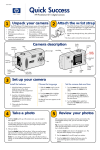
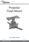
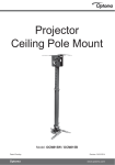
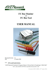
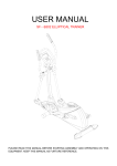
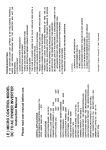
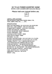
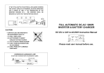
INSTALLATION
Step-6 —Cables management:
A. from top of casing by breaking the tag on the cover.
B. for concealed cable from wall.
C. remove End Cap, slide Silde Covers out from Arm, run cables and slide covers back to place.
Short Throw
Projector Wall
Mount
Slide covers
End Cover
slide
(A)
7a
(B)
(C)
Hand Knob
Slide
Rotate
7b
screen
Pan / Tilt
B
Step-7 —Adjustments:
7a. Projection distance (B) - refer to
Projector User Manual and dependant
on the required diagonal size of
image, adjust the distance from the
“face of the whiteboard” to the “front
of the projector” (nearest part to
screen) by loosening the Hand Knob
and sliding the projector mount along
the wall arm.
7b. Pan / Tilt / Rotate Projector to
adjust the projection image onto the
screen.
Steel cable
Step-8 — Dependant on the weight of projector,
use steel cable (not included) for reinforcement
by inserting the cable through the eye-hook
at the front of the arm and tie to the ceiling if
needed.
Eye-hook
Model: AV890-1500
NOTE: Do consult a qualifi ed and authorized service technician if you encounter any technical difficulties. We are not
liable for any damage or injuries arising from any improper installation or mishandling.
ABtUS SIGAPORE PTE LTD
www.abtussingapore.com
Revision 0
AVIT LTD
www.abtus.co.nz
AVIT LTD
www.abtus.co.nz
User Operation Guide
PACKAGING CONTENT
INSTALLATION
Step-3 — Mount Wall Arm (Item 1 ) onto wall by using the Lag Bolts and Washers (in Item 4) provided.
Lag bolts and Washers
Item-1
Wall Arm —1 set
Item - 2
Universal Mount
—1 set
Item - 3
Screw bag 1 —1 set
Item - 3
Screw bag 2 —1 set
INSTALLATION
Step-1 — Mark the position on the wall for the Wall Plate as shown in Diagram 1.
Note: Mounting position will be
vary dependent on the Brand
and Model of Projector used.
Please refer to Projector User
Manual for installation details.
Universal
Mount
A-1
To find dimention A-1,
A-1 = (offset distance) - 6.15cm
To find dimention A, align Top
of image to the edge Screen or
refer to Projector User Manual
for details.
Step-4 — Fix Universal Mount (Item 2
) with Base Spacer (“M” in Item 3) and
Screws (“A” -”I” in Item 3) onto Hitachi
projector.
Base
Spacer
Centre Line
of Wall Plate
A
Projector
CG of
Projector
Lens
Offset distance
Centre line of Image/
Projector Lens
Top of Image
Step-5 — Lift and insert the assembled
projector (in Step-4) into the short
pipe adaptor of the Wall Arm. Insert
the Locking L-bracket (in Item 4) and
secure with M8 socket cap screw and
nut (in Item 4).
insert
insert
Step-2 — Marks position of the Wall Plate mounting holes. Drill and insert Wall Anchors (in Item 4)
into concrete wall. Note: Do not use Wall Anchor for mounting on wooden wall.
Locking
L-bracket
markings
Holes for
concealed cables
Hammer
Gently
Push in
*Specifications are subject to changes without notice.