1
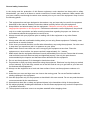
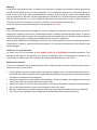
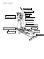
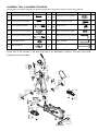
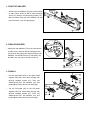
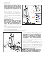
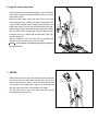
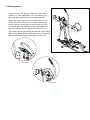
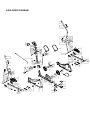
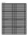
USER MANUAL
SF—E602 ELLIPTICAL TRAINER
PLEASE READ THIS MANUAL BEFORE STARTING ASSEMBLY AND OPERATING ON THIS
EQUIPMENT. KEEP THIS MANUAL AS FURTURE REFERENCE.
General safety instructions
In the design and the production of this fitness equipment, much attention has been paid to safety.
Nevertheless, you need at all times to remain conscious of certain safety measures. Make certain that
you have carefully read through the whole user manual prior to your use of the equipment. Keep in mind
the following points:
1. This equipment has not been designed to be used as a toy and must only be used for the purposes
described in this manual. Read the instructions below carefully before using this equipment.
2. Keep children and animals away from the equipment. Children’s curiosity may probably cause
inappropriate operation on this equipment. If children are allowed to use the equipment, they should
only do so under supervision and after receiving instructions regarding its proper use. Under no
circumstances should the equipment be used as a toy.
3. Always consult with your physician prior to making use of this equipment or any other fitness
equipment.
4. Always wear safe and comfortable clothing when you are using fitness equipment. Preferably, wear
sports shoes or aerobic footwear.
5. In the event you should feel faint or suffer other discomforts, stop using the equipment. You also need
to stop when you experience pain in or pressure on your joints.
6. Make certain that no more than one user is occupying the equipment at one time. Place the
equipment on a level surface; the space required is approximately 2 x 1 metres.
7. Make certain that the equipment has been correctly assembled prior to its use. Ensure that all screws,
nuts and bolts have been fitted correctly and tightened properly. Use only the parts that are
recommended by the importer and that have been delivered with the equipment.
8. Do not use the equipment if it is damaged or has broken down.
9. Pay attention to how your body reacts after using the equipment. Dizziness is a sign that you worked
out too intensely. If you feel dizzy, stretch out on the floor and do not try to get back on your feet until
the dizziness has disappeared.
10. Always use the equipment on a level and clean surface. Never use the equipment outdoors or in
water.
11. Avoid that your arms and legs come too close to the moving parts. Do not stuff articles inside the
existing openings in the equipment.
12. Use this equipment only for the purposes as described in this user manual. Do not use parts that were
not recommended by the manufacturer.
13. Ascertain that there are no sharp and pointed objects in the immediate vicinity of the equipment.
14. We advise physically challenged individuals to use this fitness equipment only under the supervision
of qualified instructors.
15. The equipment must have come to a complete standstill before stepping down.
Warning
Consult with your physician prior to starting your exercises. A frequent and intensive training programme
should first be approved by your family physician. This is especially important for individuals above 35
years of age or for those with physical problems. Carefully read through the entire user manual before
you start exercising. We are in no wise responsible for personal injury or physical strains and discomforts
that are caused by the use of this equipment and cannot be held liable in case of their occurrence.
Carefully save these instructions. Incorrect or extreme use may lead to personal injury.
Note: the maximum permissible weight on this equipment is 221LBS.
Assembly
This user manual has been put together in order to simplify the assembly of the equipment and at the
same time to explain its correct use. Please make certain to carefully read through this manual. In order to
familiarise yourself with the parts of the equipment, we recommend that you carefully study the general
reference drawing prior to starting the assembly and the use of the equipment.
Place all parts needed for the assembly on the floor in an orderly manner and remove all packing material.
Check the list of parts to verify what items are present. For the actual assembly we make referral to the
following pages.
Thank you for your purchase
we thank you for your purchase of this SUNNY HEALTH & FINTNESS household equipment. This
equipment will help you in improving your general conditioning and in developing your muscles in the
correct way. In addition, you can now enjoy all of these benefits inside your own home.
Maintenance and use
Consult your physician before starting the exercises. A frequent and strenuous workout program must be
approved by your physician first.
•
•
•
•
•
•
The equipment requires a regular check-up to prevent physical injury. This means that bolts and nuts
should be frequently checked for their proper tightening and that the equipment in general should be
checked for cracks and sharp edges etc.
Defective components must be replaced immediately. If this is not feasible, the equipment must be put
out of order until the required repairs have been made.
NB! Do not smoke or use fire near the equipment, as some of the plastic components are flammable.
Do not use the equipment in front of a burning stove and/or fire place.
Persons suffering from a plastics allergy should consult their physician before using the equipment.
Do not touch any cylinders on the equipment as they become extremely hot during use
PRODUCT OVERVIEW:
手握心跳
MEGA HAND PULSE
右上扶手管组
RIGHT UPPER SWING BAR
握把管
ROUND GRIP BAR
左上扶手组
ROUND GRIP握把饰盖
BAR HOUSING
LEFT UPPER SWING BAR
METER
仪表
TCD Tension control device
TCD阻力调节器
扶手饰盖
SWING
BAR HOUSING
LOWER SWING BAR
下扶手组
METRE POST BOTTOM HOUSING
脚踏管饰盖
LEFT PEDAL
脚踏板左
前贴地管组
FRONT
STABILIZER
PEDAL SUPPORT TUBE HOUSING
仪表杆护盖
脚踏板右
RIGHT PEDAL
外盖
BODY COVER
REAR STABILIZER
后贴地片组
ASSEMBLY TOOL & ASSEMBLY DIAGRAM
Please identify the following assembly tools’ sketch photo illustration which will be helpful in the process of assembly.
NO.
NAME & SPEC
DRAWING
QTY.
NO.
NAME & SPEC
DRAWING
QTY.
13
M4*35 ROUND CROSS SCREW
4
15
OD20*ID8.5*2.0T FLAT WASHER
2
25
M4*20 ROUND CROSS SCREW
8
70
M8*20 CARRIAGE SCREW
2
27
M10*50 CARRIAGE SCREW
4
59
M8 NYLON CAP
2
23
OD20*ID10.5*2.0T FLAT WASHER
4
36
M5*16 ROUND CROSS SCREW
2
51
M8*72 INNER HEXAGON SCREW
2
5MM INNER HEXAGON SPANNER
1
17
M8 SPRING WASHER
2
6MM L SPANNER
1
49
M8 ARC WASHER
2
TUM SPANNER
1
Please refer to the numbers of the parts that need to be assembled in advance. The body cover inside
mechanism is pre-assembled.
43
44
36
92
7
25
65
9
5
6
7
54
9
14
8
12
14
55
12
13
18
64
19
21
23
22
24
25
29
22
23
36
21
48
17
49
15
16
17
62
25
29
56
13
51 17 49 52
19
24
27
25
15
59
53
93
23
60
26
25
51
17
49
61
84
30
27
96
28
23
26
70
70
69
74
15
59
15
59
1. FRONT STABILIZER
51 17 49 52
- Attach the front stabilizer (52) to the front bottom
of main frame. Insert an M8*72 inner hexagon
screw (51) through an M8 spring washer (17),
M8 arc washer (49) and front stabilizer as well
the main frame. Lock this group tight.
51
17
49
69
2. REAR STABILIZER
-Attach the rear stabilizer (74) to the rear bottom
of main frame. Insert an M8*20 carriage screw
(70) through the main frame bottom and the rear
stabilizer; use OD20*ID8.5*2.0T flat waher (15)
and M8 nylon cap (59) to lock the screw on.
59 15 70
70
70
69
74
15
59
15
59
3. PEDALS
- Put the right pedal (93) on the right pedal
support tube (96). Inert them through with
M10*50 carriage screws (27). Then use
OD20*ID10.5*2.0T flat washers (23) and
pedal adjust knobs (26) to lock them tight.
27
93
23
26
30
27
- Put the left pedal (28) on the left pedal
support tube (30). Insert them through with
M10*50 carriage screws (27). Then use
OD20*ID10.5*2.0T flat washers (23) and
pedal adjust knobs (26) to lock them tight.
28
23
26
96
4. METER POST
0 6
6 4
- First please remove the two M8*70 inner
hexagon screws (48), two M8 nylon caps (59),
six M8 spring washers (17), two M8 arc washers
(49), four M8*20 inner hexagon screws (16) and
four OD20*ID8.5*2.0T flat washers which are
pre-assembled on the bottom of the meter post.
- Make the TCD knob on the meter post (46) at
the lowest level. Under this circumstance, the
sensor wire will come out the post at its longest
48
status which will help the wire porst connection
17
49
15
as follows.
16
17
- Slide the meter post bottom housing (60) onto
62
the meter post (46) and keep it at the upper area
of the post. (See Pic.1-A)
- Move the meter post (46) with the housing close
to the main frame. Connect the TCD upper
segment (62) with the TCD lower segment (61).
(See Pic. 1-B); connect the ports of sensor wire
upper section (53) with the sensor wire lower
section(84)
- Silde the upper meter post onto the lower one.
Use the removed screws and washers to lock this
part according to right photo drawing.
- Fix the meter post bottom housing (60) firm on the body covers.
Pic. 1-A
1
15
59
53
Pic.1-B
2
60
61
84
3
4
5. Lower swing bars & pedal support tubes
-
18
25
29
19
21
23
22
24
21
19
24
96
30
25
94
25
29
22
23
Use 6MM L spanner and tum spanner to
disassemble the M10*76 inner hexagon screws (22),
OD20*ID10.5*2.0T flat washer (23), lower swing bar
axle (21) and M10*6.35T nylon caps (19) which are
pre-assembled on the left and right pedal support
tubes (30,96).
- Insert the lower swing bar axle (21) into tube bushing
of the lower swing bar (18).
- Then fix the lower swing bar (18) between the U
shape end of the let pedal support tube (18). Then
assemble this joint with parts: M10*76 inner hexagon
screws (22), OD20*ID10.5*2.0T flat washer (23), lower
swing bar axle (21) and M10*6.35T nylon caps (19)
- Use M4*20 round cross screws (25) to lock the L+R
pedal support tube housing (24,29)
【NOTE】:The left & right lower swing bar assembly way is
exactly the same procedure. The left lower swing bar (18)
and right lower swing bar (19) can be used alternatively.
6. Upper & lower swing bars
- Remove M8*36 inner hexagon screws (7) and M8*6.35T
nylon caps (9) which are pre-assembled on the L+R lower
swing bars (18,94).
- Move the right upper swing bar (92) close to the right
lower swing bar (94); combine the port of hand pulse wire
1 (6) out from the right upper swing bar with the port of the
hand pulse wire 3 (54) out from the right lower swing bar.
- Slide the right upper swing bar onto the right lower swing
bar and insert them through with removed M8*36 inner
hexagon screw (7). Finally use the M8*6.35T nylon cap
(9) to lock up them.
- Cap the swing bar front (12) and rear (14) housing and
use M4*35 round cross screw (13) to fix them.
92
7
9
5
6
54
7
14
9
14
8
55
12
13
13
12
13
18
94
【NOTE】:The procedure of assembling left right swing bar (5) is
the same as above.
7. METER
- Take the meter screws (44) from the back of the meter (43)
- Connect the sensor wire upper section (53) with sensor
wire on the back of the meter; Connect the hand pulse wire
3 (54) and the hand pulse wire 4 (55) out of the meter post
with the hand pulse wire on back side of the meter.
- Fix the meter (43) on top of the meter post and use the
removed screws to lock it on.
43
44
54 55 53
8. Round grip bar
- Please remove the M8*25 screw (45), M8 spring
washer (17) and OD20*ID8.5*1.5T flat washer (15)
which are pre-assembled on the round grip bar (56).
- Attach the round grip bar front housing (64) on the
meter post. Use an M5*16 round cross screw (36) to
lock it; insert the round grip bar (56) through the holes
in housing (64). Use removed screws and washers to
lock the round bar onto the meter post. (See Pic.2-A)
- Join round grip bar rear housing (65) with the front housing
(64). Finally use an M5*16 round cross screw (36) and two
M4*20 round cross screws to lock them up. (Pic. 2-B)
36
25
65
45
17
15
64
Pic. 2-A
Pic. 2-B
36
56
Meter User Manual.
BUTTON:
1.MODE:Press this button to select all functions and confirm all function values. Hold the button for 2 seconds
to total reset all function values.
2.SET:Press to set function value.
3.RESET:Press to reset function value and back to last setting stage.
Hold the button for 2 seconds to reset all function values and clear all functions.
4.BODY FAT:Press to enter into body fat measure function.
5.RECOVERY:Press this button to enter the fitness test if the pulse excess 72.
The ranking of the test resolute is from F1 to F6.
FUNCTION:
1.SCAN:Automatically scan through functions on under line display.
2.TIME:Automatically count up exercise time during exercise.
Automatically count down exercise time from target during exercise.
3.SPEED:Display current exercise speed during exercise.
4.DISTANCE:Automatically count up exercise distance during exercise.
Automatically count down exercise distance from target during exercise.
5.CAL:Automatically count up calories consumption during exercise.
Automatically count down calories consumption from target during exercise.
6.RPM:Revolution per minute.
7.PULSE:Display current heart rate (beat per minute).
8.BODY FAT:Display about body fat function (BMI, BMR, FAT% and so on).
9.RECOVERY:Detect and display heart rate recovery.
10.TEMPERATURE:Display temperature at room.
NOTE:
1. Stop exercise for 4 seconds, all functions stop working, heart rate function may still working if pulse sensor
still on.
2. Computer automatically stops calculation after 4 minutes without any signal input.
3. Computer automatically shut down after 4 minutes without any signal input.
4. Replace the batteries while the computer displays improperly.
5. Display temperature at room after the computer shut down.
6. Battery specification: 2pcs of AA size batteries
EXPLODED DIAGRAM
1
2
92
3
4
7
9
6
11
16
17
15
12
13
14
10
11
36
25
65
94
43
44
45
17
15
57
58
46
10
47
95
93
47
54
55
56
64
25
20
19
36
29
62
2
17
49
15
16
59
59
15
76
60
77 19 78
15
5
50 51
17 49 52 41 50
66 79 80
10
11
12
13
90 91
100
27
68 85 86 87 88
84
41
19 23
28
70
67
25
70
15
59
15
59
29
30
24
25
23
26
68 69
71
31
32
32
23
19
33 17 15 34
89
73
74
75
63
72
35 34 101 36 37
38
39
40
41
42
32
23
19
38
81 82 83 19
7
8
9
31
32
96
24
25
26
23
97
41
40
61
48
3
27
10
1
14
11
15
16
17
18
19
20
20
21
22
23
20
21
23
22
53
63
98 99 36
34 35 34 15 17 16
PART LIST
NO.
1
2
3
4
NAME & SPECIFICATION
5
6
7
8
9
10
11
12
13
14
15
16
17
18
swing bar end cap
swing bar foam
mega hand pulse
M3*10 hand pulse screw
left upper swing bar
hand pulse wire 1
M8*36 inner hexagon screw
hand pulse wire 2
M8*6.5T nylon cap
wire cap
bearing 6002(ABEC5)
swing bar front housing
M4*35 round cross screw
swing bar rear housing
OD20*ID8.5*2.0T flat washer
M8*20 inner hexagon screw
M8 srping wahser
left lower swing bar
19
20
21
22
23
24
25
26
27
28
29
30
31
32
33
34
35
36
37
38
39
40
41
42
43
44
45
46
47
48
49
50
51
M10*6.35 T nylon cap
lower swing bar bushing
lower swing bar axle
M10*76 inner hexagon screw
OD20*ID10.5*2.0T flat washer
pedal support tube housing (L)
M4*20 round cross screw
pedal adjust knob
M10*50 carriage screw
left pedal
pedal support tube housing (R)
left pedal support tube
M10*50 inner hexagon screw
little copper bushing
M8*20 inner hexagon screw
pedal axle
pedal support tube adjustor
M5*16 round cross screw
left crank housing
5/16-18*25 outer hexagon screw
left crank
crank end cap
M4*20 round cross screw
left body cover
meter
M5*10 scrwe (fixed on meter)
M8*25 inner hexagon screw
meter post
joint axle housing
M8*70 inner hexagon screw
OD16*ID8.5*1.5T arc washer
front trasporation wheel
M8*72 inner hexagon screw
QTY.
2
2
2
4
NO.
52
53
54
55
1
1
4
1
4
4
4
2
4
2
15
7
14
1
56
57
58
59
60
61
62
63
64
65
66
67
68
69
front stabilizer
sensor wire upper section
hand pulse wire 3
hand pulse wire 4
round grip bar
screw with TCD
M5 arc wahser with TCD
M8 nylon cap
meter post botton housing
TCD lower segment
TCD upper segment
M4*12 cross screw
round grip bar front housing
round grip bar rear housing
OD14*ID10.5*1.5T flat washer
crank axle
R12 bearing
main frame
NAME & SPECIFICAITON
7
4
2
2
13
2
8
4
4
1
2
1
2
4
1
4
2
6
1
2
1
2
16
1
1
4
2
1
2
2
4
2
2
70
71
72
73
74
75
76
77
78
79
80
81
82
83
84
85
86
87
88
89
90
91
92
93
94
95
96
97
98
99
100
101
M8*20 carriage screw
rear stabilizer end cap (L)
rear stabilizer rubber wahser (L)
rear stabilizer end cap (R)
rear stabilizer
rear stabilizer rubber washer (R)
adjust wheel fixer hook
inner magnet
arc adjust wheel with bearing 6000
adjust wheel gap bushing
flywheel axle
adjust wheel fixer
gap washer
curve washer
sensor wire lower section
OD32*ID19.5*1.5T flat washer
M6 nylon cap
M6 spring washer
OD16.5*ID6.5*1.5T flat washer
belt plate (wtih magnet sensor )
crank axle
M6*18 outer hexagon screw
right upper swing bar
right pedal
right lower swing bar
round bar foam
right pedal support tube
right body cover
right crank
right crank end cap
belt
OD21.7*ID16*0.3T curve washer
QTY.
1
1
1
1
1
1
1
5
1
1
1
16
1
1
2
1
2
1
2
1
1
1
1
1
1
1
1
1
1
1
1
1
1
1
4
4
4
1
1
4
1
1
1
1
1
1
1
1
1
2