1
SUPER
®
Rack Installation for
Supermicro Switches
USER’S MANUAL
1.0
Rack Installation for Supermicro Switches
The information in this User’s Manual has been carefully reviewed and is believed to be accurate.
The vendor assumes no responsibility for any inaccuracies that may be contained in this document,
makes no commitment to update or to keep current the information in this manual, or to notify any
person or organization of the updates. Please Note: For the most up-to-date version of this
manual, please see our web site at www.supermicro.com.
Super Micro Computer, Inc. ("Supermicro") reserves the right to make changes to the product
described in this manual at any time and without notice. This product, including software and
documentation, is the property of Supermicro and/or its licensors, and is supplied only under a
license. Any use or reproduction of this product is not allowed, except as expressly permitted by
the terms of said license.
IN NO EVENT WILL SUPERMICRO BE LIABLE FOR DIRECT, INDIRECT, SPECIAL, INCIDENTAL,
SPECULATIVE OR CONSEQUENTIAL DAMAGES ARISING FROM THE USE OR INABILITY TO
USE THIS PRODUCT OR DOCUMENTATION, EVEN IF ADVISED OF THE POSSIBILITY OF
SUCH DAMAGES. IN PARTICULAR, SUPERMICRO SHALL NOT HAVE LIABILITY FOR ANY
HARDWARE, SOFTWARE, OR DATA STORED OR USED WITH THE PRODUCT, INCLUDING THE
COSTS OF REPAIRING, REPLACING, INTEGRATING, INSTALLING OR RECOVERING SUCH
HARDWARE, SOFTWARE, OR DATA.
Any disputes arising between manufacturer and customer shall be governed by the laws of Santa
Clara County in the State of California, USA. The State of California, County of Santa Clara shall
be the exclusive venue for the resolution of any such disputes. Super Micro's total liability for all
claims will not exceed the price paid for the hardware product.
California Best Management Practices Regulations for Perchlorate Materials: This Perchlorate
warning applies only to products containing CR (Manganese Dioxide) Lithium coin cells. “Perchlorate
Material-special handling may apply. See www.dtsc.ca.gov/hazardouswaste/perchlorate”
WARNING: Handling of lead solder materials used in this
product may expose you to lead, a chemical known to
the State of California to cause birth defects and other
reproductive harm.
Manual Revision 1.0
Release Date: May 16, 2011
Unless you request and receive written permission from Super Micro Computer, Inc., you may not
copy any part of this document.
Information in this document is subject to change without notice. Other products and companies
referred to herein are trademarks or registered trademarks of their respective companies or mark
holders.
Copyright © 2011 by Super Micro Computer, Inc.
All rights reserved.
Printed in the United States of America
ii
Preface
Preface
About This Manual
This manual is written for professional system integrators and PC technicians. It
provides information for the installation Supermicro switches into a rack environment. Installation and maintenance should be performed by experienced technicians only.
This manual lists compatible parts available at the time of publication. Always refer
to the Supermicro Web site for updates on supported parts and configurations at
www.supermicro.com.
iii
Rack Installation for Supermicro Switches
Manual Organization
Chapter 1 Introduction
The first chapter provides an overview of the optional CSE-PT52L rack mounting
kit and safety information for Supermicro switches.
Chapter 2 Rack Installation
This chapter covers detailed instructions for installing the switch into a rack. You
should follow the procedures given in this chapter when installing, removing or
reconfiguring your switch into a rack environment.
iv
Preface
Table of Contents
Preface
About This Manual......................................................................................................... iii
Chapter 1 Introduction
1-1
Overview.......................................................................................................... 1-1
1-2
Unpacking the System..................................................................................... 1-1
1-3
Preparing for Setup.......................................................................................... 1-1
Choosing a Setup Location.............................................................................. 1-1
Rack Precautions............................................................................................. 1-2
General Precautions........................................................................................ 1-2
Lithium Battery Precaution............................................................................... 1-3
Rack Mounting Considerations........................................................................ 1-3
Ambient Operating Temperature................................................................. 1-3
Reduced Airflow.......................................................................................... 1-3
Mechanical Loading.................................................................................... 1-3
Circuit Overloading...................................................................................... 1-4
Reliable Ground.......................................................................................... 1-4
Chapter 2 Rack Installation
2-1
Rack Mounting Instructions.............................................................................. 2-1
Identifying the Sections of the Rack Rails . .................................................... 2-1
Separating the Sections of the Rails............................................................... 2-2
2-2
Inner Rails........................................................................................................ 2-3
Installing the Inner Rails.................................................................................. 2-3
2-3
Outer Rails....................................................................................................... 2-4
Installing the Outer Rails.................................................................................. 2-4
2-4
Installing the Switch......................................................................................... 2-6
Installing the Switch into a Rack...................................................................... 2-6
Installing the Switch into a Telco rack.............................................................. 2-7
v
Rack Installation for Supermicro Switches
Notes
vi
Chapter 1 Introduction
Chapter 1
Introduction
1-1 Overview
Some Supermicro switches can be equipped with an optional rail kit (CSE-PT52L)
to make it easy to install them in a rack. This manual provides instructions for installing the CSE-PT52L mounting rails onto a rack and for installing the switch into
the mounting rails. Following these steps in the order given should enable you to
have the system operational within a minimum amount of time.
1-2 Unpacking the System
You should inspect the box the switch was shipped in and note if it was damaged
in any way. If the switch itself shows damage you should file a damage claim with
the carrier who delivered it.
Decide on a suitable location for the rack unit that will hold your switch. It should
be situated in a clean, dust-free area that is well ventilated. Avoid areas where
heat, electrical noise and electromagnetic fields are generated. You will also need
it placed near a grounded power outlet. Be sure to read the Rack, General and
Lithium Battery Precautions in the next section.
1-3 Preparing for Setup
The optional rail kit (CSE-PT52L) ships in a separate box and that box should
include two sets of rail assemblies, two rail mounting brackets and the mounting
screws needed to install the system into the rack. Read this section in its entirety
before you begin the installation procedure outlined in the sections that follow.
Choosing a Setup Location
•Leave enough clearance in front of the rack to enable you to open the front
door completely (~25 inches).
•Leave approximately 30 inches of clearance in the back of the rack to allow for
sufficient airflow and ease in servicing.
•This product is for installation only in a Restricted Access Location (dedicated
equipment rooms, service closets and similar environments).
1-1
Rack Installation for Supermicro Switches
!
Warnings and Precautions!
!
Rack Precautions
•Ensure that the leveling jacks on the bottom of the rack are fully extended to
the floor with the full weight of the rack resting on them.
•In a single rack installation, stabilizers should be attached to the rack.
•In multiple rack installations, the racks should be coupled together.
•Always make sure the rack is stable before extending a component from the
rack.
•You should extend only one component at a time - extending two or more simultaneously may cause the rack to become unstable.
General Precautions
•Review the electrical and general safety precautions that came with the components you are adding to your switch (if any).
•Determine the placement of each component in the rack before you install the
rails.
•Install the heaviest server components on the bottom of the rack first, and then
work up.
•Use a regulating uninterruptible power supply (UPS) to protect the servers and
switches from power surges, voltage spikes and to keep your system operating
in case of a power failure.
•Always keep the rack's front door and all panels and components closed when
not servicing to maintain proper cooling.
•Do not remove the cover of the switch, there are no user-serviceable components inside. Take unit to service center for repairs and servicing.
•Disconnect all power cords before servicing.
CAUTION: Slide/rail mounted equipment is not to be used as
a shelf or work space.
1-2
Chapter 1 Introduction
Lithium Battery Precaution
This switch may contain a lithium battery. There is a danger of explosion if the battery is incorrectly replaced.
•Installing the battery upside-down may reverse the polarities and cause the
battery to explode.
•Replace the battery only with the same or equivalent type recommended by
the manufacturer.
•Dispose of used batteries according to the manufacturer’s instructions.
•Do not damage the battery in any way, a damaged battery may release hazardous materials into the environment.
•Do not discard a used battery in the garbage or a public landfill.
•Please comply with the regulations set up by your local hazardous waste management agency to dispose of your used battery properly.
Rack Mounting Considerations
Ambient Operating Temperature
If installed in a closed or multi-unit rack assembly, the ambient operating temperature of the rack environment may be greater than the ambient temperature of the
room. Therefore, consideration should be given to installing the equipment in an
environment compatible with the manufacturer’s maximum rated ambient temperature (Tmra).
Reduced Airflow
Equipment should be mounted into a rack so that a hazardous condition does not
arise due to uneven mechanical loading.
Mechanical Loading
Equipment should be mounted into a rack so that a hazardous condition does not
arise due to uneven mechanical loading.
1-3
Rack Installation for Supermicro Switches
Circuit Overloading
Consideration should be given to the connection of the equipment to the power
supply circuitry and the effect that any possible overloading of circuits might have
on overcurrent protection and power supply wiring. Appropriate consideration of
equipment nameplate ratings should be used when addressing this concern.
Reliable Ground
A reliable ground (earth) must be maintained at all times. To ensure this, the rack
itself should be grounded. Particular attention should be given to power supply
connections other than the direct connections to the branch circuit (i.e. the use of
power strips, etc.).
1-4
Chapter 2 Rack Installation
Chapter 2
Rack Installation
2-1 Rack Mounting Instructions
This chapter provides information on installing the switch into a rack unit with the
CSE-PT52L rail kit. There are a variety of rack units on the market, which may mean
the assembly procedure will differ slightly. You should also refer to the installation
instructions that came with the rack unit you are using.
NOTE: This rail will fit a rack between 26" and 33.5" deep.
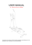
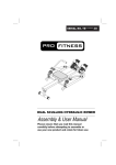
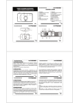
Identifying the Sections of the Rack Rails
The CSE-PT52L rail kit package includes two rack rail assemblies in the rack
mounting kit. Each assembly consists of two sections: a fixed inner rail that secures
directly to the side of the switch, and a fixed outer rail that secures directly to the
rack itself.
Inner Rail Extension
(Discard)
Inner Rail
Outer Rail Rear Bracket
Outer Rail Front Bracket
Figure 2-1: Identifying the Sections of the Rack Rails
2-1
Rack Installation for Supermicro Switches
Separating the Sections of the Rails
The CSE-PT52L rail kit ships with the front inner rail attached to the front outer rail.
These must be separated prior to installation in the rack.
Separating the Rails
1. Separate the inner rail from the outer rail by depressing the black plastic
flange inside the inner rail. This will release the outer rail.
2. Silde the inner rail forward and out of the outer rail.
3. The CSE-PT52L rail kit also includes a set of inner rail extensions. Only the
inner rails are required and you may discard the inner rail extensions.
2-2
Chapter 2 Rack Installation
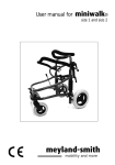
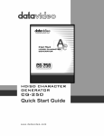
1
13
2
Figure 2-2: Installing the Inner Rail
Note: Your switch may differ from the illustrations in this manual
2-2 Inner Rails
Installing the Inner Rails
Installing the Inner Rails on the Switch
1. Place one of the inner rails on one side of the switch aligning the hook on the
side of the switch with the mounting hole in the rail. Make sure the inner rail
faces outward, as illustrated above.
2. Slide the inner rail forward so that the rail fits securely into the hook on the
side of the switch.
3. Secure the inner rail to the switch with one screw as illustrated above.
4. Repeat steps 1-2 for the remaining inner rail.
2-3
Rack Installation for Supermicro Switches
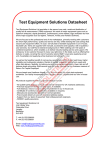
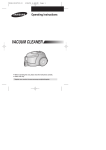
Secure to the
Front of the Rack
Attach Outer Racks
together
Secure to the
Rear of the Rack
Figure 2-3: Assembling the Outer Rails
2-3 Outer Rails
Installing the Outer Rails
Installing the Outer Rails on the Rack
1. Attach the shorter outer rail to the outside of the longer outer rail. You must
align the pins with the slides. Also, both bracket ends must face the same
direction.
2. Adjust both the shorter and longer brackets to the proper length so that the
rail fits snugly into the rack.
3. Secure the long bracket to the front side of the rack with two M5 screws and
the short bracket to the rear side of the rack with three M5 screws.
4. Repeat steps 1-4 for the remaining outer rail.
2-4
Chapter 2 Rack Installation
3
3
2
SCALE 0.380
Figure 2-4: Installing the Outer Rails onto the Rack
2-5
Rack Installation for Supermicro Switches
Figure 2-5: Installing the Switch into a Rack
Note: Your switch may differ from the illustrations in this manual
2-4 Installing the Switch
Installing the Switch into a Rack
Installing the Switch
1. Confirm that inner rails have been secured to the switch.
2. Confirm that the outer rails are installed on the rack.
3. Align the ends of the inner rails on the switch with the front of the outer rails
on the rack.
4. Slide the inner rails into the outer rails, keeping the pressure even on both
sides (you may have to depress the locking tabs when inserting). When the
switch has been pushed completely into the rack, you should hear the locking
tabs click into the locked position.
5. (Optional) Insert and tighten the thumbscrews which secure the front of the
switch to the rack.
2-6
Chapter 2 Rack Installation
Installing the Switch into a Telco rack
To install the switch into a Telco (post style) rack, use two L-shaped brackets on
either side of the switch (four total). First, determine how far the switch will extend
out the front of the rack. Larger switches should be positioned to balance the weight
between front and back. Attach the two front brackets to each side of the switch,
then position the two rear brackets with just enough space to accommodate the
width of the telco rack. Finish by sliding the switch into the rack and tightening the
brackets to the rack.
Figure 2-6: Installing the Switch into a Telco Rack
Note: Your switch may differ from the illustrations in this manual
2-7
Rack Installation for Supermicro Switches
Disclaimer (cont.)
The products sold by Supermicro are not intended for and will not be used in life support systems, medical equipment, nuclear facilities or systems, aircraft, aircraft devices,
aircraft/emergency communication devices or other critical systems whose failure to perform be reasonably expected to result in significant injury or loss of life or catastrophic
property damage. Accordingly, Supermicro disclaims any and all liability, and should
buyer use or sell such products for use in such ultra-hazardous applications, it does so
entirely at its own risk. Furthermore, buyer agrees to fully indemnify, defend and hold
Supermicro harmless for and against any and all claims, demands, actions, litigation,
and proceedings of any kind arising out of or related to such ultra-hazardous use or
sale.
2-8