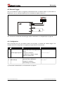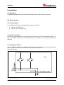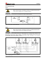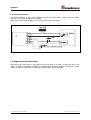
1
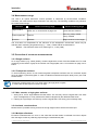
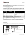
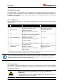
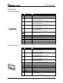
Rotary
Encoders
Linear
Encoders
System
Motion
D
Seite 2 - 52
GB
Page 53 - 104
LLB-65 (H) / LLB-500 (H)
• Software/Support CD: 490-01001
Benutzerhandbuch / User Manual
Laser-Entfernungs-Messgerät / Laser Measuring Device
LLB-65 (H) Analog
LLB-500 (H) Analog + SSI
TR - ELE - BA - DGB - 0021 - 01 10/19/2010
- Soft-No.: LLB Utility
User Manual
Laser Measuring Device
LLB-65 (H) Analog
LLB-500 (H) Analog + SSI
© TR-Electronic GmbH 2010, All Rights Reserved
Printed in the Federal Republic of Germany
10/19/2010
TR - ELE - BA - DGB - 0021 - 01
Page 53 of 104
TR-Electronic GmbH
D-78647 Trossingen
Eglishalde 6
Tel.: (0049) 07425/228-0
Fax: (0049) 07425/228-33
E-mail: [email protected]
http://www.tr-electronic.de
Copyright protection
This Manual, including the illustrations contained therein, is subject to copyright
protection. Use of this Manual by third parties in contravention of copyright
regulations is forbidden. Reproduction, translation as well as electronic and
photographic archiving and modification require the written content of the
manufacturer. Offenders will be liable for damages.
Subject to amendments
Any technical changes that serve the purpose of technical progress, reserved.
Document information
Release date/Rev. date:
Document rev. no.:
File name:
Author:
10/19/2010
TR - ELE - BA - DGB - 0021 - 01
TR-ELE-BA-DGB-0021-00.DOC
MÜJ
Font styles
Italic or bold font styles are used for the title of a document or are used for
highlighting.
Courier font displays text, which is visible on the display or screen and software
menu selections.
″<
> ″ indicates keys on your computer keyboard (such as <RETURN>).
© TR-Electronic GmbH 2010, All Rights Reserved
Page 54 of 104
Printed in the Federal Republic of Germany
TR - ELE - BA - DGB - 0021 - 01
10/19/2010
Contents
Contents
Contents ............................................................................................................................................55
Revision index ..................................................................................................................................58
1 General information ......................................................................................................................59
1.1 Applicability......................................................................................................................59
1.2 EC Declaration of conformity...........................................................................................60
1.3 Abbreviations and definitions...........................................................................................60
2 Basic safety instructions..............................................................................................................61
2.1 Definition of symbols and instructions .............................................................................61
2.2 Obligation of the operator before start-up .......................................................................61
2.3 General risks when using the product .............................................................................62
2.4 Proper use .......................................................................................................................62
2.5 Warranty and liability .......................................................................................................63
2.6 Organizational measures.................................................................................................63
2.7 Personnel qualification; obligations .................................................................................64
2.8 Safety information's .........................................................................................................65
3 Introduction....................................................................................................................................67
3.1 Product identification .......................................................................................................68
3.2 Components ....................................................................................................................69
3.3 Validity .............................................................................................................................69
3.4 Measurement range ........................................................................................................70
3.5 Prevention of erroneous measurements .........................................................................70
3.5.1 Rough surfaces................................................................................................70
3.5.2 Transparent surfaces.......................................................................................70
3.5.3 Wet, smooth, or high-gloss surfaces ...............................................................70
3.5.4 Inclined, round surfaces ..................................................................................70
3.5.5 Multiple reflections ...........................................................................................70
4 Device setup ..................................................................................................................................71
4.1 Connection.......................................................................................................................71
4.2 Controlled mode ..............................................................................................................72
4.2.1 Configuration ...................................................................................................72
4.2.2 Host software...................................................................................................72
4.3 Automatic mode...............................................................................................................73
4.3.1 Configuration ...................................................................................................73
4.4 Display Mode ...................................................................................................................74
4.5 External Trigger ...............................................................................................................75
4.5.1 Configuration ...................................................................................................75
5 Installation......................................................................................................................................76
5.1 Mounting ..........................................................................................................................76
© TR-Electronic GmbH 2010, All Rights Reserved
Printed in the Federal Republic of Germany
10/19/2010
TR - ELE - BA - DGB - 0021 - 01
Page 55 of 104
Contents
5.2 Device wiring ...................................................................................................................76
5.2.1 Power Supply...................................................................................................76
5.2.2 Cable connection .............................................................................................76
5.2.3 Shield and Ground...........................................................................................76
5.2.4 Controlled mode ..............................................................................................77
5.2.5 Automatic mode...............................................................................................78
5.3 Alignment of the laser beam............................................................................................78
6 Technical data................................................................................................................................79
6.1 Measuring accuracy ........................................................................................................79
6.2 Specifications...................................................................................................................80
7 Electrical components ..................................................................................................................81
7.1 ID switch ..........................................................................................................................81
7.2 Reset switch ....................................................................................................................81
7.3 Digital output....................................................................................................................81
7.4 Digital Input......................................................................................................................81
7.5 Analog output...................................................................................................................82
7.6 Connector ........................................................................................................................83
7.6.1 D-Sub connector..............................................................................................83
7.6.2 Screw terminal .................................................................................................83
8 Physical dimensions .....................................................................................................................84
9 Factory settings.............................................................................................................................85
9.1 Operation .........................................................................................................................85
9.2 Communication parameters ............................................................................................85
9.3 Analog outputs.................................................................................................................85
9.4 Module ID ........................................................................................................................85
9.5 Digital output 1 (DOUT1) .................................................................................................85
9.6 Digital output 2 (DOUT2) .................................................................................................85
9.7 Digital input 1 (DI1)..........................................................................................................85
9.8 User distance offset.........................................................................................................85
10 Command set...............................................................................................................................86
10.1 General ..........................................................................................................................86
10.1.1 Command termination <trm> .......................................................................86
10.1.2 Module identification N...................................................................................86
10.1.3 Parameter separator......................................................................................86
10.1.4 Set/Get Commands .......................................................................................86
10.1.5 Startup sequence...........................................................................................86
10.2 Operation commands ....................................................................................................87
10.2.1 STOP/CLEAR command (sNc) ...................................................................87
10.2.2 Distance measurement (sNg)......................................................................87
10.2.3 Signal measurement (sNm)..........................................................................87
10.2.4 Temperature measurement (sNt) ...............................................................88
10.2.5 Laser ON (sNo)............................................................................................88
© TR-Electronic GmbH 2010, All Rights Reserved
Page 56 of 104
Printed in the Federal Republic of Germany
TR - ELE - BA - DGB - 0021 - 01
10/19/2010
Contents
10.2.6 Laser OFF (sNp)..........................................................................................88
10.2.7 Single sensor, Tracking (sNh) .......................................................................89
10.2.8 Tracking with buffering – Start (sNf).............................................................89
10.2.9 Read out - Tracking with buffering (sNq).......................................................90
10.3 Configuration commands...............................................................................................90
10.3.1 Set/Get communication parameter (sNbr)....................................................90
10.3.2 Set automatic mode (sNA).............................................................................91
10.3.3 Set/Get analog output min level (sNvm) ........................................................91
10.3.4 Set/Get analog output value in error case (sNve).........................................92
10.3.5 Set/Get distance range (sNv) ........................................................................92
10.3.6 Set/Get digital output levels (sNn) .................................................................93
10.3.7 Save configuration parameters (sNs)............................................................94
10.3.8 Set configuration parameters to factory default (sNd)...................................94
10.3.9 Get Software Version (sNsv) ........................................................................94
10.3.10 Get Serial Number (sNsn)...........................................................................95
10.3.11 Get device generation and type (dg)...........................................................95
10.4 Digital Input....................................................................................................................96
10.4.1 Configure digital input (sNDI1)......................................................................96
10.4.2 Read digital input (sNRI)...............................................................................96
10.5 SSI (Synchronous serial interface)................................................................................97
10.5.1 Change from RS422 to SSI output and back (sNSSI) ..................................97
10.5.2 Set/Get error value on SSI output (sNSSIe) .................................................97
10.6 Special User Commands...............................................................................................98
10.6.1 Set/Get user distance offset (sNuof) ..........................................................98
10.6.2 User configured distance measurement (sNug)..........................................98
10.6.3 User-configured single sensor tracking (sNuh)..........................................99
10.6.4 User-configured tracking with buffering – Start (sNuf) .................................100
10.6.5 Read out – User-configured tracking with buffering (sNuq) ..........................100
10.6.6 Set user configured automatic mode (sNuA).................................................101
10.7 Error codes ....................................................................................................................102
11 Accessories .................................................................................................................................103
11.1 Viewfinder ......................................................................................................................103
11.2 Target plates..................................................................................................................103
11.3 Laser glasses ................................................................................................................103
11.4 Connection set...............................................................................................................104
11.5 Connector cover IP65....................................................................................................104
11.6 Connector with 90° cable exit IP65 ...............................................................................104
© TR-Electronic GmbH 2010, All Rights Reserved
Printed in the Federal Republic of Germany
10/19/2010
TR - ELE - BA - DGB - 0021 - 01
Page 57 of 104
Revision index
Revision index
Revision
Date
Index
First release
4/27/2010
00
Vibration and shock added to the technical data
10/19/2010
01
© TR-Electronic GmbH 2010, All Rights Reserved
Page 58 of 104
Printed in the Federal Republic of Germany
TR - ELE - BA - DGB - 0021 - 01
10/19/2010
General information
1 General information
The User Manual includes the following topics:
•
Basic safety instructions
•
Introduction
•
Device setup
•
Installation
•
Technical data
•
Electrical components
•
Physical dimensions
•
Factory settings
•
Command set
•
Accessories
As the documentation is arranged in a modular structure, this User Manual is
supplementary to other documentation, such as product datasheets, dimensional
drawings, leaflets etc.
The User Manual may be included in the customer's specific delivery package or it
may be requested separately.
1.1 Applicability
This User Manual applies exclusively to the following measuring system series with
- Analog interface
•
•
•
•
LLB65-00600
LLB65-00601
LLB65-00610
LLB65-00611
- Analog + SSI interface
•
•
•
•
LLB500-00600
LLB500-00601
LLB500-00610
LLB500-00611
The products are labelled with affixed nameplates and are components of a system.
The following documentation therefore also applies:
•
•
the operator's operating instructions specific to the system,
this User Manual
© TR-Electronic GmbH 2010, All Rights Reserved
Printed in the Federal Republic of Germany
10/19/2010
TR - ELE - BA - DGB - 0021 - 01
Page 59 of 104
General information
1.2 EC Declaration of conformity
The measuring systems have been developed, designed and manufactured under
observation of the applicable international and European standards and directives.
A corresponding declaration of conformity can be requested from TR-Electronic
GmbH.
The manufacturer of the product, TR-Electronic GmbH in
D-78647 Trossingen, operates a certified quality assurance system in accordance
with ISO 9001.
1.3 Abbreviations and definitions
EC
European Community
EMC
Electro Magnetic Compatibility
ESD
Electro Static Discharge
IEC
International Electrotechnical Commission
LLB
Laser Measuring Device
VDE
German Electrotechnicians Association
© TR-Electronic GmbH 2010, All Rights Reserved
Page 60 of 104
Printed in the Federal Republic of Germany
TR - ELE - BA - DGB - 0021 - 01
10/19/2010
Basic safety instructions
2 Basic safety instructions
2.1 Definition of symbols and instructions
Means that death, serious injury or major damage to property
could occur if the stated precautions are not met.
WARNING !
Means that minor injuries or damage to property can occur if
the stated precautions are not met.
CAUTION !
Means that eye injury can occur from laser light if the stated
precautions are not met.
WARNING !
Indicates important information's or features and application
tips for the product used.
2.2 Obligation of the operator before start-up
As an electronic device the measuring system is subject to the regulations of the EMC
Directive.
It is therefore only permitted to start up the measuring system if it has been
established that the system/machine into which the measuring system is to be fitted
satisfies the provisions of the EC EMC Directive, the harmonized standards,
European standards or the corresponding national standards.
© TR-Electronic GmbH 2010, All Rights Reserved
Printed in the Federal Republic of Germany
10/19/2010
TR - ELE - BA - DGB - 0021 - 01
Page 61 of 104
Basic safety instructions
2.3 General risks when using the product
The product, hereinafter referred to as "the measuring system", is manufactured
according to state-of-the-art technology and accepted safety rules. Nevertheless,
improper use can pose a danger to life and limb of the user or third parties, or
lead to impairment of the measuring system or other property!
Only use the measuring system in a technically faultless state, and only for its
designated use, taking safety and hazard aspects into consideration, and observing
this User Manual! Faults which could threaten safety should be eliminated without
delay!
2.4 Proper use
The measuring system is used to measure distances and to condition the
measurement data for the subsequent control of industrial control processes.
Proper use also includes:
• observing all instructions in this User Manual,
• observing the nameplate and any prohibition or instruction symbols on the
measuring system,
• observing the enclosed
configurations etc.,
documentation,
e.g.
product
insert,
connector
• observing the operating instructions from the machine or system manufacturer,
• operating the measuring system within the limit values specified in the technical
data.
The following areas of use are especially forbidden:
• in areas in which interruption of the laser beam can cause damage or personal
injury, for example by covering the laser lens opening,
• in environments where heavy rain, snow, fog, vapours or direct sunlight etc. can
impair the laser intensity,
• in environments where there is an explosive atmosphere,
• for medical purposes
Where there is a danger of physical injury and damage to property arising
from jumps in the position of the measuring system!
WARNING !
-
As the measuring system does not constitute a safety component, a
plausibility check of the measuring system values must be performed
through the subsequent control system.
-
It is mandatory for the operator to integrate the measuring system into his
own safety concept.
© TR-Electronic GmbH 2010, All Rights Reserved
Page 62 of 104
Printed in the Federal Republic of Germany
TR - ELE - BA - DGB - 0021 - 01
10/19/2010
Basic safety instructions
2.5 Warranty and liability
The General Terms and Conditions ("Allgemeine Geschäftsbedingungen") of TRElectronic GmbH always apply. These are available to the operator with the Order
Confirmation or when the contract is concluded at the latest. Warranty and liability
claims in the case of personal injury or damage to property are excluded if they
result from one or more of the following causes:
•
Non-designated use of the measuring system.
•
Improper assembly, installation, start-up and programming of the measuring
system.
•
Incorrectly undertaken work on the measuring system by unqualified
personnel.
•
Operation of the measuring system with technical defects.
•
Mechanical or electrical modifications to the measuring systems undertaken
autonomously.
•
Repairs carried out autonomously.
•
Third party interference and Acts of God.
2.6 Organizational measures
• The User Manual must always be kept accessible at the place of use of the
measuring system.
• In addition to the User Manual, generally applicable legal and other binding
accident prevention and environmental protection regulations are to be observed
and must be mediated.
• The respective applicable national, local and system-specific provisions and
requirements must be observed and mediated.
• The operator is obliged to inform personnel on special operating features and
requirements.
• The personnel instructed to work with the measuring system must have read and
understood the User Manual, especially the chapter “Basic safety instructions”
prior to commencing work.
• The nameplate and any prohibition or instruction symbols applied on the
measuring system must always be maintained in a legible state.
• Do not undertake any mechanical or electrical modifications on the measuring
system, apart from those explicitly described in this User Manual.
• Repairs may only be undertaken by the manufacturer or a facility or person
authorized by the manufacturer.
© TR-Electronic GmbH 2010, All Rights Reserved
Printed in the Federal Republic of Germany
10/19/2010
TR - ELE - BA - DGB - 0021 - 01
Page 63 of 104
Basic safety instructions
2.7 Personnel qualification; obligations
• All work on the measuring system must only be carried out by qualified personnel.
Qualified personnel includes persons, who, through their training, experience and
instruction, as well as their knowledge of the relevant standards, provisions,
accident prevention regulations and operating conditions, have been authorized
by the persons responsible for the system to carry out the required work and are
able to recognize and avoid potential hazards.
• The definition of “Qualified Personnel” also includes an understanding of the
standards VDE 0105-100 and IEC 364 (source: e.g. Beuth Verlag GmbH, VDEVerlag GmbH).
• Define clear rules of responsibilities for the assembly, installation, start-up and
operation. The obligation exists to provide supervision for trainee personnel !
© TR-Electronic GmbH 2010, All Rights Reserved
Page 64 of 104
Printed in the Federal Republic of Germany
TR - ELE - BA - DGB - 0021 - 01
10/19/2010
Basic safety instructions
2.8 Safety information's
Eye injury from laser radiation!
WARNING !
-
The measuring system functions with a red light laser Class 2. In the case of
Class 2 laser devices, the eye is not endangered if the exposure to the laser
radiation is very brief (up to 0.25 s) and accidental. For this reason, devices of
this class can be used without additional protective measures, provided the
application does not require one to look into the laser beam deliberately for
longer periods, i.e. 0.25 s, or to look repeatedly into the laser beam or the
reflected laser beam.
The existence of the blinking reflex for the protection of the eyes may not
be assumed. Therefore eyes should be closed consciously, or the head
should be turned away immediately!
-
The measuring system must be installed in such a way that the exposure of
persons to the laser beam can only occur accidentally.
-
The laser beam must only extend as far as is necessary for the range
measurement. The beam must be limited at the end of the useful range by a
target area in such a way as to minimize the danger from direct or diffuse
reflection.
-
The area outside the operating range where the unshielded laser beam falls
should be limited as far as possible and should remain out of bounds,
particularly in the area above and below eye level.
-
Heed the laser safety regulations according to DIN EN 60825-1 in their most
current version.
-
Observe the legal and local regulations applicable to the operation of laser
units.
© TR-Electronic GmbH 2010, All Rights Reserved
Printed in the Federal Republic of Germany
10/19/2010
TR - ELE - BA - DGB - 0021 - 01
Page 65 of 104
Basic safety instructions
•
Danger of physical injury and damage to property !
-
Do not point the viewfinder directly at the sun, the viewfinder functions as a
magnifying glass and can injure eyes and/or cause damage inside the
LLB.
-
De-energize the system before carrying out wiring work or opening and
closing electrical connections.
-
Do not carry out welding if the measuring system has already been wired up
or is switched on.
-
Ensure that the laser warning symbol on the measuring system is well visible
anytime.
-
No use of accessories from other manufacturers.
-
Ensure that the area around the assembly site is protected from corrosive
media (acid, etc.).
-
Do not open the measuring system.
WARNING !
CAUTION !
•
Disposal
If disposal has to be undertaken after the life span of the device, the respective
applicable country-specific regulations are to be observed.
•
Cleaning
Clean the lens opening of the measuring system regularly with a damp cloth.
Do not use any aggressive detergents, such as thinners or acetone!
© TR-Electronic GmbH 2010, All Rights Reserved
Page 66 of 104
Printed in the Federal Republic of Germany
TR - ELE - BA - DGB - 0021 - 01
10/19/2010
Introduction
3 Introduction
The LLB (optional LLB (H = with heating) is a powerful distance-measuring instrument for integration
into industrial applications. It allows accurate and contactless distance measurement over a wide
range using the reflection of a laser beam:
Figure 1: Standard application
Key features:
● Compatible with TR LLB-60 Laser Distance Sensor
●
LLB-65 / LLB-500 measurement range on natural surfaces 0.05 m up to approx. 65 m
●
LLB-500 measurement range on (reflective) target plate 0.05 m up to approx. 500 m
●
Serial interface (RS232 and RS422)
●
SSI interface (LLB-500 only)
●
Connection of up to 10 modules on a single RS422 line
●
Wide range power supply (9...30 VDC), heating option (24...30 VDC)
●
Programmable analog output (0/4...20 mA)
●
Two programmable digital outputs (DO1 and DO2)
●
Digital output for error signalization (DOE)
●
One programmable digital input (DI1)
●
ASCII protocol to control external displays
●
D-Sub connector and screw terminal joint for easy connection
●
IP65 (protected against ingress of dust and water)
●
4 LEDs for status signalling
●
Complementary configuration software available at web site www.tr-electronic.de or Support CD
●
Optional: Internal heater for module operation down to -40 °C
●
Laser class II (<0.95 mW)
●
Accessories for easy use of the sensor
For easy startup with the device, please use the free configuration software from our
web-page: http://www.tr-electronic.de/ or Support CD
© TR-Electronic GmbH 2010, All Rights Reserved
Printed in the Federal Republic of Germany
10/19/2010
TR - ELE - BA - DGB - 0021 - 01
Page 67 of 104
Introduction
3.1 Product identification
The product is identified by the label on the top of the enclosure:
LLB-65 Version with a measuring rate of up to 6 Hz.
Version
Typical Accuracy
1.5 mm
3 mm
Standard version
LLB-65
Part No.: LLB65-00600
LLB-65
Part No.: LLB65-00601
Extended temperature range
LLB-65 (H)
Part No.: LLB65-00610
LLB-65 (H)
Part No.: LLB65-00611
LLB-500 Version with a measuring rate of up to 25 Hz.
Version
Typical Accuracy
1 mm
3 mm
Standard version
LLB-500
Part No.: LLB500-00600
LLB-500
Part No.: LLB500-00601
Extended temperature range
LLB-500 (H)
Part No.: LLB500-00610
LLB-500 (H)
Part No.: LLB500-00611
© TR-Electronic GmbH 2010, All Rights Reserved
Page 68 of 104
Printed in the Federal Republic of Germany
TR - ELE - BA - DGB - 0021 - 01
10/19/2010
Introduction
3.2 Components
1
Status LEDs
2
15-Pin D-Sub connector
6
Screw terminal
7
ID switch
status signalling
RS422, RS232, SSI, analog, digital output
RS422, RS232, SSI, analog, digital output
3
Cable gland (M16 x 1.5 mm)
defines the module ID for RS422 operation
8
Laser beam outlet
9
Receiver optics
for connection cable insertion
4
Cover
provides access to electrical components
5
Reset switch
10 Product label
resets the LLB to default settings
see 2.8 on page 65.
3.3 Validity
This manual is valid for LLB devices with the following software version:
Interface software version:
Module software version:
0100 or later
0100 or later
To get the software version for the LLB use the command described in 10.3.9 Get Software Version
(sNsv) on page 94
© TR-Electronic GmbH 2010, All Rights Reserved
Printed in the Federal Republic of Germany
10/19/2010
TR - ELE - BA - DGB - 0021 - 01
Page 69 of 104
Introduction
3.4 Measurement range
The LLB is an optical instrument, whose operation is influenced by environmental conditions.
Therefore, the measurement range achieved in use may vary. The following conditions may influence
the measurement range:
Influence
Factors increasing range
Factors reducing range
Target surface
Bright and reflective surfaces such as the target Matt and dark surfaces
plates, see 11 Accessories on page 103.
green and blue surfaces
Airborne particles
Clean air
Dust, fog, heavy rainfall,
heavy snowfall
Sunshine
Darkness
Bright sunshine on the target
The LLB does not compensate for the influence of the atmospheric environment, which may be
relevant when measuring long distances (e.g. > 150m). These effects are described in:
B.Edlen: “The Refractive Index of Air, Metrologia 2”, 71-80 (1966)
3.5 Prevention of erroneous measurements
3.5.1 Rough surfaces
On a rough surface (e.g. coarse plaster), measure against the center of the illuminated area. To avoid
measuring to the bottom of gaps in the surface use a target plate, see 11 Accessories on page 103 or
board.
3.5.2 Transparent surfaces
To avoid measuring errors, do not measure against transparent surfaces such as colourless liquids
(such as water) or (dust-free) glass. In case of unfamiliar materials and liquids, always carry out a trial
measurement.
Erroneous measurements can occur when aiming through panes of glass,
or if there are several objects in the line of sight.
3.5.3 Wet, smooth, or high-gloss surfaces
1 Aiming at an “acute“ angle deflects the laser beam. The LLB may receive a signal that is too weak
(error message 255) or it may measure the distance targeted by the deflected laser beam.
2 If aiming at a right angle, the LLB may receive a signal that is too strong (error message 256).
3.5.4 Inclined, round surfaces
Measurement is possible as long as there is enough target surface area for the laser spot.
3.5.5 Multiple reflections
Erroneous measurements can occur in the case that the laser beam is reflected from other objects
than the target. Avoid any reflecting object along the measurement path.
© TR-Electronic GmbH 2010, All Rights Reserved
Page 70 of 104
Printed in the Federal Republic of Germany
TR - ELE - BA - DGB - 0021 - 01
10/19/2010
Device setup
4 Device setup
We recommend performing the configuration steps in an office before mounting the device, especially
if you are not familiar with the LLB.
The LLB supports two types of operation modes:
• Controlled mode
•
Automatic mode (for use in stand-alone operation)
The first decision to be taken is the type of operation mode that will be used to transmit the distance
measurement data. While the controlled mode provides maximum flexibility and accuracy, it is often
not suitable for integration into existing PLCs or analog environments. In such cases the automatic
mode might be preferred.
Influence
controlled mode
automatic mode
(with analog output and/or digital outputs)
Accuracy
Maximum measurement accuracy
Accuracy depends on signal scaling
(see 10.3.5 Set/Get distance range (sNv)
on page 92)
Flexibility
Access to full command set
Limited
Integration
Requires protocol implementation
Wiring of AO and/or DO signals
Connection
Connection of up to 10 LLB to a single
Point-to-point connection
RS-422 line.
The following two sections describe the configuration of the LLB for the controlled and automatic
modes.
4.1 Connection
To be able to configure the LLB, it must be powered and connected to a PC. Figure 2 shows the
necessary connections. On the PC, any terminal program can be used to communicate with the
module. A configuration utility is also available on the web page www.tr-electronic.de.
Figure 2: Connection for LLB configuration
© TR-Electronic GmbH 2010, All Rights Reserved
Printed in the Federal Republic of Germany
10/19/2010
TR - ELE - BA - DGB - 0021 - 01
Page 71 of 104
Device setup
4.2 Controlled mode
In controlled mode, each operation of a LLB is triggered by a command sent from a host system over
a serial line. While a single device can be connected to the host system using the RS232 interface, up
to 10 devices can be connected to a single serial RS422 line. The related command set is described
in Chapter 10 on page 86.
4.2.1 Configuration
After connecting the module, the steps below are necessary to configure the LLB for the controlled
interface mode.
No.
Action
Comment
1
Changes of the module ID are
activated after a power cycle.
Set ID switch
Example for module 0:
Change the ID Switch to position 0
Command
Set ID switch to position 0
Power OFF; Wait 10s;
Power ON
Set the LLB to the controlled mode, if
not already in controlled mode.
2
3
Set controlled mode
Set communication
parameters
Example for module 0:
Set to controlled mode by means of
the stop command.
If necessary, change the settings for
the serial interface.
Example for module 0:
Set serial interface to 19200 Baud,
8 Bit, no Parity
s0c<trm>1)
s0br+2<trm>1)
Power OFF; Wait 10s; Change
settings on the host;
Power ON
1) Commands are described in chapter 10 Command set on page 86
If the communication parameters of the module are lost, please reset the configuration to the factory
settings (9 Factory settings on page 85) using the reset button (see 7.2 Reset switch on page 81).
Please note that the ID switch must be reset manually.
4.2.2 Host software
Host software is required for operation of the LLB in controlled mode. When connecting multiple
devices to a single serial line (RS422), strict Master-Slave communication must be implemented
(LLB operates as slave).
•
WARNING !
Danger of physical injury and damage to property by accidentally
commands !
-
Careful testing of the host software together with the devices prior to
installation is strongly recommended.
© TR-Electronic GmbH 2010, All Rights Reserved
Page 72 of 104
Printed in the Federal Republic of Germany
TR - ELE - BA - DGB - 0021 - 01
10/19/2010
Device setup
4.3 Automatic mode
The automatic mode is provided for host-less operation of the LLB. The analog and digital outputs are
updated according the configuration described below as soon as the unit is powered up.
Analog Output
The analog output is configurable and works with two ranges:
–
–
0..20 mA
4..20 mA
Digital Outputs
Three digital outputs are included in the LLB. Two are programmable, while the third is used to
signal an error state of the device.
4.3.1 Configuration
After connecting the module, the following steps are necessary to configure the LLB for automatic
mode.
No.
1
2
Action
Set current output
range
Set distance range
Comment
Command
Defines if the current output range
from 0 to 20 mA or from 4 to 20 mA.
Example for module 0:
Set current output range from 4mA
to 20 mA.
s0vm+1<trm>1)
Defines minimum distance (Dmin) and
the maximum distance (Dmax) for the
distance range of the analog output. s0v+00000000+00100000<trm>1)
Example for module 0:
Set distance range from 0m to 10m
3
4
Set analog output in
case of an error
Configure digital
output
Sets the current, that should be
applied in case of an error.
Example for module 0:
Set current to 0 mA in case of an
error.
Set the ON and OFF level for the
digital outputs.
Example for module 0:
DO 1: off=2000 mm on=2005 mm
DO 2: off=4000 mm on=4005 mm
s01+00020000+00020050<trm>1)
s02+00040000+00040050<trm>1)
© TR-Electronic GmbH 2010, All Rights Reserved
Printed in the Federal Republic of Germany
10/19/2010
s0ve+000<trm>1)
TR - ELE - BA - DGB - 0021 - 01
Page 73 of 104
Device setup
No.
5
Action
Save settings
Comment
The changed configuration must be
saved to make it permanent.
Example for module 0:
Save settings for module 0
Command
s0s<trm>1)
Set the LLB to the automatic mode
with the desired update rate.
6
Set automatic mode
Example for module 0:
Set measurement rate to fastest
possible speed.
s0A+0<trm>1)
1) Commands are described in chapter 10 Command set on page 86.
If the communication parameters of the module have been lost, please reset the configuration to the
factory settings (9 Factory settings on page 85) using the reset button (see 7.2 Reset switch on page
81). Please note that the ID switch must be reset manually.
4.4 Display Mode
If Display Mode is enabled, the LLB formats the measured distance as ASCII string, which is
understood by External Displays with a serial interface. Since the LLB outputs this formatted string
automatically on the serial interface after completing a measurement. Measurement results can be
displayed on an external display without an additional controller.
For a detailed description of this mode, please contact TR-Electronic.
© TR-Electronic GmbH 2010, All Rights Reserved
Page 74 of 104
Printed in the Federal Republic of Germany
TR - ELE - BA - DGB - 0021 - 01
10/19/2010
Device setup
4.5 External Trigger
The LLB includes the option of triggering measurements with an external switch or push button on
Digital Input 1 (DI 1). Using the Digital Input DI 1 disables the Digital Output DO 1.
The command to activate the external trigger option is described in 10.4 Digital Input on page 96.
4.5.1 Configuration
After connecting the LLB, the following steps are necessary to activate the external trigger. The
example shows the configuration for triggering a single distance measurement.
No.
Action
Comment
Command
Defines the action for a trigger event
on DI1.
1
5
Activate digital input DI1 Example for module 0:
Configure DI1 to trigger a single
distance measurement.
Save settings
The changed configuration must be
saved to make it permanent.
s0DI1+2<trm>1)
s0s<trm>1)
Example for module 0:
Save settings for module 0
1) Commands are described in 10 Command set on page 86
© TR-Electronic GmbH 2010, All Rights Reserved
Printed in the Federal Republic of Germany
10/19/2010
TR - ELE - BA - DGB - 0021 - 01
Page 75 of 104
Installation
5 Installation
5.1 Mounting
Three M4 threaded holes in the bottom of the LLB make it easy to mount the device.
5.2 Device wiring
5.2.1 Power Supply
For trouble-free operation use a separate power supply for the LLB.
●
●
LLB: 9…30 VDC, 0.5 A
LLB (H): 24…30 VDC, 2.5 A
5.2.2 Cable connection
A ferrite core must be fitted to the connecting cable. Use a ferrite core with an impedance of 150 Ω to
260 Ω at 25 MHz and 640 Ω to 730 Ω at 100 MHz. For example you can use KCF-65 from KE
Kitagawa.
5.2.3 Shield and Ground
The LLB contains two electrically isolated grounds, the general ground (GND) and the analog ground
(AGND). GND and AGND are connected to the housing by a RC element.
Please see Figure 3.
Figure 3: Connection between shield, Ground (GND) and Analog Ground (AGND)
© TR-Electronic GmbH 2010, All Rights Reserved
Page 76 of 104
Printed in the Federal Republic of Germany
TR - ELE - BA - DGB - 0021 - 01
10/19/2010
Installation
5.2.4 Controlled mode
RS232
•
Danger of physical injury and damage to property by undefined interface states !
-
WARNING !
Never connect multiple LLB´s on a RS232 serial line
Only point-to-point communication is possible when using the RS232 interface.
Figure 4: Point-to-point connection with RS 232
RS422
•
Danger of physical injury and damage to property by undefined interface states !
-
WARNING !
Ensure, that all LLB´s are set to different ID numbers
It is possible to connect multiple devices on a single RS422 line. To ensure proper operation, strict
Master-Slave communication must be applied. It is important, that the Master has full control of the
communication and never initiates a new communication before termination of the previous
communication (answer from the LLB or timeout).
Figure 5: Connecting multiple devices with RS422
© TR-Electronic GmbH 2010, All Rights Reserved
Printed in the Federal Republic of Germany
10/19/2010
TR - ELE - BA - DGB - 0021 - 01
Page 77 of 104
Installation
5.2.5 Automatic mode
The analog interface of the LLB is isolated from the rest of the device. When using the analog
interface, connect the analog ground (AGND).
Make sure, that the total resistance in the analog path is lower than 500 Ω.
Figure 6: Connection of an instrument and a PLC
5.3 Alignment of the laser beam
Alignment of the laser beam is often difficult when the target is far away, as the laser spot is not
visible. An optional telescopic viewfinder is available which simplifies alignment significantly. Please
refer to chapter 11 Accessories on page 103 for a description of the viewfinder.
© TR-Electronic GmbH 2010, All Rights Reserved
Page 78 of 104
Printed in the Federal Republic of Germany
TR - ELE - BA - DGB - 0021 - 01
10/19/2010
Technical data
6 Technical data
6.1 Measuring accuracy
The measuring accuracy corresponds to the ISO-recommendation
ISO/R 1938-1971 with a statistical confidence level of 95.4 %
(i.e. ± twice the standard deviation σ, refer to diagram on the right).
The typical measuring accuracy relates to average conditions for
measuring.
Measuring accuracy
LLB65-00600
± 1.5 mm
LLB65-00601
± 3 mm
LLB65-00610
± 1.5 mm
LLB65-00611
± 3 mm
LLB500-00600
± 1 mm
LLB500-00601
± 3 mm
LLB500-00610
± 1 mm
LLB500-00611
± 3 mm
The values above are valid in the tracking mode.
The maximum measuring error relates to unfavourable conditions such as:
-
Highly reflective surfaces (e.g. reflector tapes)
-
Operation at the limits of the permitted temperature range, adaptation to ambient temperature
canceled
-
Very bright ambient conditions, strong heat shimmer
Maximum measuring error
LLB65-00600
± 2 mm
LLB65-00601
± 5 mm
LLB65-00610
± 2 mm
LLB65-00611
± 5 mm
LLB500-00600
± 2 mm
LLB500-00601
± 5 mm
LLB500-00610
± 2 mm
LLB500-00611
± 5 mm
The LLB does not compensate changes of atmospheric environment. These changes can influence
the accuracy if measuring long distances (>150 m) under conditions very different from 20 °C, 60 %
relative humidity and 953 mbar air pressure. The influences of the atmospheric environment are
described in:
B.Edlen: “The Refractive Index of Air, Metrologia 2”, 71-80 (1966)
© TR-Electronic GmbH 2010, All Rights Reserved
Printed in the Federal Republic of Germany
10/19/2010
TR - ELE - BA - DGB - 0021 - 01
Page 79 of 104
Technical data
6.2 Specifications
Typical measuring accuracy for:
1)
LLB65-00600, LLB65-00610
1)
LLB65-00601, LLB65-00611
1)
LLB500-00600, LLB500-00610
1)
LLB500-00601, LLB500-00611
± 1.5 mm at 2 σ
± 3 mm at 2 σ
± 1 mm at 2 σ
± 3 mm at 2 σ
Accuracy of the analog output
LLB-65:
LLB-500:
0.2 % full scale
0.1 % full scale
Smallest unit displayed:
0.1 mm
Measuring range on natural surfaces:
0.05 m to approx. 65 m
Measuring range on orange (reflective) target plate
LLB-500:
see chapter 11 Accessories on page 103.
0.05 m to 500 m
Measuring reference:
from front edge, see 8 Physical dimensions
Diameter of laser spot at target with a distance of:
4 mm at 5 m
8 mm at 10 m
15 mm at 30 m
Time for a measurement:
- Single measurement
LLB-65 / LLB-500:
- Tracking
LLB-65:
LLB-500:
0.3 s to approx. 4 s
0.15 s to approx. 4 s
40 ms to 4 s
Light source:
Laser diode 620-690 nm (red)
IEC 60825-1:2001; Class 2
FDA 21CFR 1040.10 and 1040.11
Beam divergence: 0.16 x 0.6 mrad
-9
Pulse duration: 0.45x10 s
Maximum radiant power: 0.95 mW
Laser Life Time:
>50'000 h at 20 °C
ESD:
IEC 61000-4-2: 1995 +A1 +A2
EMC:
EN 61000-6-4
EN 61000-6-2
Power supply:
LLB-65/-500:
LLB-65/-500 (with heating):
150 x 80 x 55 mm
Dimensions:
2)
Operation temperature :
2
LLB-65/-500:
LLB-65/-500 (with heating):
-10 °C to +50 °C
-40 °C to +50 °C
Storage temperature:
-40 °C to +70 °C
Degree of Protection:
IP65; IEC60529 (protected against ingress of dust and water)
Vibration, DIN EN 60068-2-6: 1996
≤ 50 m/s2, sine 50-2000 Hz
Schock, DIN EN 60068-2-27: 1995
≤ 300 m/s2, half-sine 11 ms
Weight:
690 g
720 g
Interfaces:
1
9 ... 30 V DC 0.6 A
24 ... 30 V DC 2.5 A
LLB-65/-500:
LLB-65/-500 (with heating):
1 RS232/RS422 interface
1 SSI interface (only LLB-500)
1 programmable analog output 0/4 .. 20 mA
2 programmable digital outputs
1 programmable digital input
1 digital output for error status
) See 6.1 Measuring accuracy on page 79.
) In case of permanent continuous measurement (tracking mode) the max. temperature is reduced to 45°C
© TR-Electronic GmbH 2010, All Rights Reserved
Page 80 of 104
Printed in the Federal Republic of Germany
TR - ELE - BA - DGB - 0021 - 01
10/19/2010
Electrical components
7 Electrical components
7.1 ID switch
This switch is used to set the module ID and can be set from 0 to 9. Default setting is 0.
7.2 Reset switch
To reset the module to factory settings do the following:
● Switch OFF the power for the module
● Press the reset button and keep it pressed
● Switch on the power for the module with pressed reset button
● Keep the reset button pressed until all LEDs on the module are illuminated
● Release the reset button.
● Switch the power OFF and wait 5 seconds.
● Switch on the power and wait until the green power LED is on.
7.3 Digital output
DOUT
On
The LLB contains two digital outputs for level monitoring (DO 1 and DO 2) and one
digital output for error signalization (DO E). These outputs are open drain outputs
as shown in Figure 7 and can drive up to 200mA. Maximum switching voltage is
30 VDC. In the ON state, the FET transistor is electro conductive.
Figure 7: Open drain output
7.4 Digital Input
The Digital Output (DO 1) can be configured as a Digital Input (DI 1). This is useful for triggering
measurements by means of an external switch or push button. Please refer to chapter 10.4 Digital
Input on page 96.
Low Level is:
High Level is:
U DI1 < 2 VDC
U DI1 > 9 VDC and U DI1 < 30 VDC
© TR-Electronic GmbH 2010, All Rights Reserved
Printed in the Federal Republic of Germany
10/19/2010
TR - ELE - BA - DGB - 0021 - 01
Page 81 of 104
Electrical components
7.5 Analog output
The analog output of the LLB is a current source (0..20 mA or 4..20 mA). It is capable of driving loads
up to 500 Ω. The analog output has an accuracy of ± 0.2 % for LLB-65 and ± 0.1 % for LLB-500 full
scale.
LLB-65:
uMax =
Range (Conf MaxDist − Conf MinDist )
=
500
500
uMax = max. uncertainty
ConfMaxDist = Distance programmed for the max. output current
ConfMinDist = Distance programmed for the min. output current
LLB-500:
uMax =
Range (Conf MaxDist − Conf MinDist )
=
1000
1000
uMax = max. uncertainty
ConfMaxDist = Distance programmed for the max. output current
ConfMinDist = Distance programmed for the min. output current
Example:
The configured measurement range is 0...20 m and the actual measured distance is 14 m. This results
in a measurement uncertainty of ± 0.04 m (0.2 % of 20 m) for the LLB-65 and ± 0.02 m (0.1 % of
20 m) for the LLB-500, which includes all parameters (temperature drift, sensor accuracy, linearity,
target color etc.). The uncertainty decreases, if the ambient temperature is stable.
© TR-Electronic GmbH 2010, All Rights Reserved
Page 82 of 104
Printed in the Federal Republic of Germany
TR - ELE - BA - DGB - 0021 - 01
10/19/2010
Electrical components
7.6 Connector
7.6.1 D-Sub connector
15
8
9
1
Pin
Designator
Description
1
Rx
RS232 receive line
2
Tx
3
T-
4
T+
5
R-
6
R+
7
PWR
9
DO 1
RS232 send line
- RS422 send line negative
- SSI data output negative
(only for LLB-500 and if configured for SSI)
- RS422 send line positive
- SSI data output positive
-(only for LLB-500 and if configured for SSI)
- RS422 receive line negative
- SSI clock input negative
(only for LLB-500 and if configured for SSI)
- RS422 receive line positive
- SSI clock input positive
(only for LLB-500 and if configured for SSI)
DC Power
+ 9 V…+30 V for LLB
+24 V…+30 V for LLB (with heating)
Digital output 1 (Open Drain) or Digital input 1
10
DO 2
Digital output 2 (Open Drain)
11
DO E
Digital output for error signalization (Open Drain)
12
AGND
Analog ground
13
AO
Analog output (0/4..20 mA)
14
GND
Ground line
15
GND
Ground line
8
7.6.2 Screw terminal
Pin
No.1
Designator
Description
1
R+
2
R-
3
T+
4
T-
5
Tx
- RS422 receive line positive
- SSI clock input positive
(only for LLB-500 and if configured for SSI)
- RS422 receive line negative
- SSI clock input negative
(only for LLB-500 and if configured for SSI)
- RS422 send line positive
- SSI data output positive
(only for LLB-500 and if configured for SSI)
- RS422 send line negative
- SSI data output negative
(only for LLB-500 and if configured for SSI)
RS232 Transmit line
6
Rx
RS232 Receive line
7
AGND
Analog ground
8
AO
Analog output (0/4..20mA)
9
DO E
Digital output for error signalization (Open Drain)
10
DO 2
Digital output 2 (Open Drain)
11
DO 1
Digital output 1 (Open Drain) or Digital input 1
12
GND
13
PWR
Ground line
Power DC
+9 V...+30 V LLB
+24 V...+30 V LLB (with heating)
© TR-Electronic GmbH 2010, All Rights Reserved
Printed in the Federal Republic of Germany
10/19/2010
TR - ELE - BA - DGB - 0021 - 01
Page 83 of 104
Physical dimensions
8 Physical dimensions
All dimensions in mm
© TR-Electronic GmbH 2010, All Rights Reserved
Page 84 of 104
Printed in the Federal Republic of Germany
TR - ELE - BA - DGB - 0021 - 01
10/19/2010
Factory settings
9 Factory settings
9.1 Operation
Mode:
Controlled Mode
9.2 Communication parameters
Baud:
Data bit:
Parity:
Stop bit:
19200
7
Even
1
9.3 Analog outputs
Min output:
Range min:
Range max:
Error output:
4 mA
0m
10 m
0 mA
9.4 Module ID
ID Number:
0
9.5 Digital output 1 (DOUT1)
ON:
OFF:
2 m + 5 mm = 2005 mm
2 m – 5 mm = 1995 mm
9.6 Digital output 2 (DOUT2)
ON:
OFF:
1 m – 5 mm = 995 mm
1 m + 5 mm = 1005 mm
9.7 Digital input 1 (DI1)
Inactive, configured as output
9.8 User distance offset
User distance offset = 0 mm
© TR-Electronic GmbH 2010, All Rights Reserved
Printed in the Federal Republic of Germany
10/19/2010
TR - ELE - BA - DGB - 0021 - 01
Page 85 of 104
Command set
10 Command set
10.1 General
10.1.1 Command termination <trm>
All commands for the LLB are ASCII based and terminated <trm> with <cr><lf>.
10.1.2 Module identification N
Since the module can be addressed with the ID switch, the ID is represented in the commands by N.
At the location of the N insert the Module ID.
10.1.3 Parameter separator
The command syntax uses the '+' sign as parameter separator. The '+' sign can be replaced by the
minus '-' sign if applicable by the command.
10.1.4 Set/Get Commands
All configuration commands that are used to set configuration values can also be used to read the
currently set value by omitting the parameter. The command syntax is described as follows:
Set Command
Get Command
sNuof+xxxxxxxx<trm>
sNuof<trm>
Return successful
gNof?<trm>
gNuof+xxxxxxxx<trm>
Return Error
gN@Ezzz<trm>
gN@Ezzz<trm>
Parameters
N
xxxxxxxx
zzz
Command
Module ID (0..9)
Offset in 1/10 mm; + positive / - negative
Error code
10.1.5 Startup sequence
After power on the LLB does all the initializations and sends a start sequence gN?. On this sequence,
the N stands for the Module ID. After sending this start sequence, the LLB is ready to use.
© TR-Electronic GmbH 2010, All Rights Reserved
Page 86 of 104
Printed in the Federal Republic of Germany
TR - ELE - BA - DGB - 0021 - 01
10/19/2010
Command set
10.2 Operation commands
10.2.1 STOP/CLEAR command (sNc)
Stops the current execution and resets the status LEDs as well as the digital outputs.
Command
Command
sNc<trm>
Return successful
gN?<trm>
Return Error
gN@Ezzz<trm>
Parameters
N
zzz
Module ID (0..9)
Error code
10.2.2 Distance measurement (sNg)
Triggers simple measurement of distance. Each new command cancels an active measurement.
Command
Command
sNg<trm>
Return successful
gNg+xxxxxxxx<trm>
Return Error
gN@Ezzz<trm>
Parameters
N
xxxxxxxx
zzz
Module ID (0..9)
Distance in 1/10 mm
Error code
10.2.3 Signal measurement (sNm)
Signal measurement can be done continuously or with a single measurement. The signal strength is
returned as a relative number in the range of 0 to 8 million.
Command
Command
sNm+c<trm>
Return successful
gNm+xxxxxxxx<trm>
Return Error
gN@Ezzz<trm>
N
c
Module ID (0..9)
0: single measurement
xxxxxxxx
zzz
Use only with one sensor!
1: repetitive measurement
Signal strength (range 0.. 8 millions)
Error code
Parameters
© TR-Electronic GmbH 2010, All Rights Reserved
Printed in the Federal Republic of Germany
10/19/2010
TR - ELE - BA - DGB - 0021 - 01
Page 87 of 104
Command set
10.2.4 Temperature measurement (sNt)
Triggers measurement of the temperature inside the sensor.
Command
Command
sNt<trm>
Return successful
gNt+xxxxxxxx<trm>
Return Error
gN@Ezzz<trm>
Parameters
N
xxxxxxxx
zzz
Module ID (0..9)
Temperature in 0.1°C
Error code
10.2.5 Laser ON (sNo)
Switches laser beam ON for easy adjustment.
Command
Command
sNo<trm>
Return successful
gN?<trm>
Return Error
gN@Ezzz<trm>
N
zzz
Parameters
Module ID (0..9)
Error code
10.2.6 Laser OFF (sNp)
Switches laser OFF.
Command
Command
sNp<trm>
Return successful
gN?<trm>
Return Error
gN@Ezzz<trm>
Parameters
N
zzz
Module ID (0..9)
Error code
© TR-Electronic GmbH 2010, All Rights Reserved
Page 88 of 104
Printed in the Federal Republic of Germany
TR - ELE - BA - DGB - 0021 - 01
10/19/2010
Command set
10.2.7 Single sensor, Tracking (sNh)
•
Danger of physical injury and damage to property by undefined interface states !
-
WARNING !
Never use this command if more than one module is connected to the
RS232/RS422 line
Triggers continuous measurement of the distance. This command is not to be used with more than
one LLB on the RS-232/RS-422 line. The measurements are continued until the STOP/CLEAR
command (sNc) is issued. The status LEDs and the digital outputs are updated corresponding to the
new measured distance.
Command
Command
sNh<trm>
Return successful
gNh+xxxxxxxx<trm>
Return Error
gN@Ezzz<trm>
Parameters
N
xxxxxxxx
zzz
Module ID (0..9)
Distance in 0.1 mm
Error code
10.2.8 Tracking with buffering – Start (sNf)
Triggers continuous measurement of the distance with internal buffering in the module (buffer for one
measurement). The rate of measurements is defined with the sampling time. If the sampling time is
set to zero, the measurements are executed as fast as possible. The last measurement can be read
out from the module with the command sNq. The measurements are continued until the 'sNc'
command is issued.
Set Command
Get Command
sNf+xxxxxxxx<trm>
sNf<trm>
Return successful
gNf?<trm>
gNf+xxxxxxxx<trm>
Return Error
gN@Ezzz<trm>
gN@Ezzz<trm>
Parameters
N
xxxxxxxx
zzz
Command
Module ID (0..9)
Sampling rate in 10 ms (if 0 -> max possible rate)
Error code
© TR-Electronic GmbH 2010, All Rights Reserved
Printed in the Federal Republic of Germany
10/19/2010
TR - ELE - BA - DGB - 0021 - 01
Page 89 of 104
Command set
10.2.9 Read out - Tracking with buffering (sNq)
After starting “tracking with buffering” with the command sNf, the last measurement can be read out
from the module with the command sNq.
Command
Command
sNq<trm>
Return successful
gNq+xxxxxxxx+c<trm>
Return Error
gN@Ezzz+c<trm>
Module ID (0..9)
Distance in 0.1 mm
0 = no new measurement since last sNq command
1 = one new measurement since last sNq command, not overwritten
2 = more than one measurement since last sNq command, overwritten
Error code
N
xxxxxxxx
Parameters
c
zzz
10.3 Configuration commands
10.3.1 Set/Get communication parameter (sNbr)
Sets the communication parameters for the serial interface.
This command saves all configuration parameters to Flash.
The changed baud rate is activated after the next power on.
Bold = default parameters (first use or after reset)
Command
Command
sNbr+y<trm>
Return successful
gN?<trm>
Return Error
gN@Ezzz<trm>
Module ID (0..9)
Defines the new settings
N
y
%
Parameters
Baud rate
Data bit
Parity
Baud rate
Data bit
Parity
0
1200
8
N
6
9600
7
E
1
9600
8
N
7
19200
7
E
2
19200
8
N
8
38400
8
N
3
1200
7
E
9
38400
7
E
4
2400
7
E
10
115200
8
N
5
4800
7
E
11
115200
7
E
© TR-Electronic GmbH 2010, All Rights Reserved
Page 90 of 104
%
Printed in the Federal Republic of Germany
TR - ELE - BA - DGB - 0021 - 01
10/19/2010
Command set
10.3.2 Set automatic mode (sNA)
This command activates the automatic mode of the LLB. It triggers continuous measurement of the
distance and sets the analog and digital outputs according to the measured distance values. The rate
of measurements is defined with the sampling time. If the sampling time is set to zero, the
measurements are executed as fast as possible.
The automatic mode is active until the sNc command is issued.
●
The operating mode is stored in the LLB and activated immediately. This mode is also
activated after next power ON.
●
Internally “tracking with buffering” is started (command sNf). Therefore the last
measurement can also be read out from the module with the command sNq.
Command
Command
sNA+xxxxxxxx<trm>
Return successful
gNA?<trm>
Return Error
gN@Ezzz<trm>
Parameters
Module ID (0..9)
Sampling time in 10 ms (if 0 -> max possible rate)
Error code
N
xxxxxxxx
zzz
10.3.3 Set/Get analog output min level (sNvm)
This command sets the minimum analog output current level (0 or 4 mA).
Set Command
Get Command
sNvm+x<trm>
sNvm<trm>
Return successful
gNvm?<trm>
gNvm+x<trm>
Return Error
gN@Ezzz<trm>
gN@Ezzz<trm>
Command
N
x
Parameters
zzz
Module ID (0..9)
Minimum output for analog out
0: 0 mA
1: 4 mA
Error code
© TR-Electronic GmbH 2010, All Rights Reserved
Printed in the Federal Republic of Germany
10/19/2010
TR - ELE - BA - DGB - 0021 - 01
Page 91 of 104
Command set
10.3.4 Set/Get analog output value in error case (sNve)
This command sets the analog output current level in mA in case of an error. This level can be lower
than the minimum level set in 10.3.3 Set/Get analog output min level (sNvm).
Set Command
Get Command
sNve+xxx<trm>
sNve<trm>
Return successful
gNve?<trm>
sNve+xxx<<trm>
Return Error
gN@Ezzz<trm>
gN@Ezzz<trm>
Command
Module ID (0..9)
Value in case of an error in 0.1mA
Error code
N
xxx
zzz
Parameters
10.3.5 Set/Get distance range (sNv)
Sets the minimum and maximum distances corresponding to the minimum and maximum analog
output current levels.
0...20 mA
Aout
4...20 mA
DIST Dmin
20 mA
D max Dmin
Aout
DIST
Dmin
Dmax
Aout
Analog current output
Actual measured distance
Distance programmed for the minimum output current
Distance programmed for the maximum output current
Set Command
Command
DIST Dmin
16 mA 4 mA
D max Dmin
Get Command
sNv+xxxxxxxx+yyyyyyyy<trm> sNv<trm>
Return successful
gNv?<trm>
gNv+xxxxxxxx+yyyyyyyy<trm>
Return Error
gN@Ezzz<trm>
gN@Ezzz<trm>
Parameters
N
xxxxxxxx
yyyyyyyy
zzz
Module ID (0..9)
Minimum distance in 1/10 mm corresponding to 0 mA / 4 mA
Maximum distance in 1/10 mm corresponding to 20 mA
Error code
© TR-Electronic GmbH 2010, All Rights Reserved
Page 92 of 104
Printed in the Federal Republic of Germany
TR - ELE - BA - DGB - 0021 - 01
10/19/2010
Command set
10.3.6 Set/Get digital output levels (sNn)
Sets the distance levels at which the digital outputs are switched ON and OFF with a hysteresis.
Two different situations are possible:
ON Distance > OFF Distance
The ON level of the hysteresis is larger than the
OFF level. With an increasing distance, the
digital output is switched on (open drain output is
closed) when the distance exceeds the ON level.
With a decreasing distance, the digital output is
switched off (open drain output is open) when the
distance falls below the OFF level.
ON Distance < OFF Distance
The ON level of the hysteresis is smaller than the
OFF level. With a decreasing distance, the digital
output is switched on (open drain output is
closed) when the distance falls below the ON
level. With an increasing distance, the digital
output is switched off (open drain output is open)
when the distance exceeds the OFF level.
Set Command
Get Command
sNn+xxxxxxxx+yyyyyyyy<trm>
sNn<trm>
Return successful
gNn?<trm>
gNn+xxxxxxxx+yyyyyyyy<trm>
Return Error
gN@Ezzz<trm>
gN@Ezzz<trm>
Parameters
N
n
xxxxxxxx
yyyyyyyy
zzz
Command
Module ID (0..9)
Digital output port (1 or 2)
Distance ON level in 1/10 mm for switching digital output ON
Distance OFF level in 1/10 mm for switching digital output OFF
Error code
© TR-Electronic GmbH 2010, All Rights Reserved
Printed in the Federal Republic of Germany
10/19/2010
TR - ELE - BA - DGB - 0021 - 01
Page 93 of 104
Command set
10.3.7 Save configuration parameters (sNs)
This command saves all configuration parameters, which are set by the commands above. The
parameters are written to the Flash Memory.
Command
Command
sNs<trm>
Return successful
gNs?<trm>
Return Error
gN@Ezzz<trm>
N
zzz
Parameters
Module ID (0..9)
Error code
10.3.8 Set configuration parameters to factory default (sNd)
This command restores all configuration parameters to their factory default values. The parameters
are written to the Flash Memory.
The communication parameters are also reset to factory settings.
Command
Command
sNd<trm>
Return successful
gN?<trm>
Return Error
gN@Ezzz<trm>
N
zzz
Parameters
Module ID (0..9)
Error code
10.3.9 Get Software Version (sNsv)
Retrieves the software version of the LLB.
Command
Command
sNsv<trm>
Return successful
gNsv+xxxxyyyy<trm>
Return Error
gN@Ezzz<trm>
Parameters
N
xxxx
yyyy
zzz
Module ID (0..9)
Module software version
Interface software version
Error code
© TR-Electronic GmbH 2010, All Rights Reserved
Page 94 of 104
Printed in the Federal Republic of Germany
TR - ELE - BA - DGB - 0021 - 01
10/19/2010
Command set
10.3.10 Get Serial Number (sNsn)
Retrieves the serial number.
Command
Command
sNsn<trm>
Return successful
gNsn+xxxxxxxx<trm>
Return Error
gN@Ezzz<trm>
Parameters
N
xxxxxxxx
zzz
Module ID (0..9)
Serial number of the device
Error code
10.3.11 Get device generation and type (dg)
This command returns the device type, generation and current communication settings.
Command
Command
dg<trm>
Return successful
gNdg+xxx+yz?<trm>
Return Error
gN@Ezzz<trm>
N
xxx
Parameters
y
z
zzz
Module ID (0..9)
Bit coded number to identify the device:
0x53 (83) LLB-65
not used
Comunication settings (see command sNbr+C)
Error code
© TR-Electronic GmbH 2010, All Rights Reserved
Printed in the Federal Republic of Germany
10/19/2010
TR - ELE - BA - DGB - 0021 - 01
Page 95 of 104
Command set
10.4 Digital Input
The following commands configure the terminal
DO1. This port can also be used as digital input.
For safety reasons, always use a resistor to
protect the connection terminal.
10.4.1 Configure digital input (sNDI1)
The digital output 1 of the LLB can also be used as digital input. Its state can be read or trigger a
configurable action. Use the following command to configure the behavior of the digital input.
On active digital input, the digital output function of DO1 is deactivated.
Set Command
Get Command
sNDI1+xxxxxxxx<trm>
sNDI1<trm>
Return successful
gNDI1?<trm>
sNDI1+xxxxxxxx<trm>
Return Error
gN@Ezzz<trm>
gN@Ezzz<trm>
Command
N
Module ID (0..9)
xxxxxxxx 0: Digital input inactive (DO1 active)
1:
activate the digital input to read out its state with the command
10.4.2 Read digital input (sNRI).
2:
Trigger Distance measurement (sNg)
3:
Start/Stop Single sensor Tracking (sNh)
4:
Start/Stop Tracking with buffering (sNf)
zzz
Error code
Parameters
10.4.2 Read digital input (sNRI)
Displays the state of the digital input, if the input is not inactive.
Command
Command
sNRI<trm>
Return successful
gNRI+x<trm>
Return Error
gN@Ezzz<trm>
Parameters
N
x
zzz
Module ID (0..9)
0: Input Off (Signal Low)
1: Input On (Signal High)
Error code
© TR-Electronic GmbH 2010, All Rights Reserved
Page 96 of 104
Printed in the Federal Republic of Germany
TR - ELE - BA - DGB - 0021 - 01
10/19/2010
Command set
10.5 SSI (Synchronous serial interface)
Only implemented in the LLB-500.
10.5.1 Change from RS422 to SSI output and back (sNSSI)
If the SSI interface should be used at the same port where normally the RS422 resides, it can be
switched. This setting will only be activate until next power OFF. To keep it, use the sNs command.
Set Command
Get Command
sNSSI+c<trm>
sNSSI<trm>
Return successful
gNSSI?<trm>
gNSSI+c<trm>
Return Error
gN@Ezzz<trm>
gN@Ezzz<trm>
Command
Parameters
Module ID (0..9)
0: switch to (or stay in) RS422 mode
1: switch to (or stay in) SSI mode
Error code
N
c
zzz
10.5.2 Set/Get error value on SSI output (sNSSIe)
In measuring error case, the SSI output will have the value, which is stored as the SSI error value. To
change it, the sNSSIe command can be used: The value can be in the range (0…16777215). This
value will will only be available until next power OFF. To keep it, use the sNs command.
Set Command
Get Command
sNSSIe+xxxxxxxx<trm>
sNSSIe<trm>
Return successful
gNSSIe?<trm>
gNSSIe+xxxxxxxx<trm>
Return Error
gN@Ezzz<trm>
gN@Ezzz<trm>
Command
Parameters
N
xxxxxxxx
zzz
Module ID (0..9)
A value within 0 and 16777215.
Error code
© TR-Electronic GmbH 2010, All Rights Reserved
Printed in the Federal Republic of Germany
10/19/2010
TR - ELE - BA - DGB - 0021 - 01
Page 97 of 104
Command set
10.6 Special User Commands
The special user commands can be configured by the user and are an extension to the standard
commands. Use these commands carefully and only if you really understand what they do.
10.6.1 Set/Get user distance offset (sNuof)
The user can set an individual overall offset correction for all distance measurement commands in this
'Special User Command' section. The standard distances measurement commands are not involved.
Set Command
Get Command
sNuof+xxxxxxxx<trm>
sNuof<trm>
Return successful
gNof?<trm>
gNuof+xxxxxxxx<trm>
Return Error
gN@Ezzz<trm>
gN@Ezzz<trm>
Parameters
N
xxxxxxxx
zzz
Command
Module ID (0..9)
Offset in 1/10 mm; + positive / - negative
Error code
10.6.2 User configured distance measurement (sNug)
Triggers simple distance measurement, similar to the command 10.2.2 Distance measurement (sNg)
on page 87. This command returns the distance corrected with the user offset (and user gain) as set
with the command 10.6.1 Set/Get user distance offset (sNuof). Each new command cancels an
active measurement.
This command takes the user distance offset into account (sNuof).
Command
Command
sNug<trm>
Return successful
gNug+xxxxxxxx<trm>
Return Error
gN@Ezzz<trm>
Parameters
N
Module ID (0..9)
xxxxxxxx Distance in 0.1 mm
zzz
Error code
© TR-Electronic GmbH 2010, All Rights Reserved
Page 98 of 104
Printed in the Federal Republic of Germany
TR - ELE - BA - DGB - 0021 - 01
10/19/2010
Command set
10.6.3 User-configured single sensor tracking (sNuh)
•
Danger of physical injury and damage to property by undefined interface states !
-
WARNING !
Never use these commands if more than one module is connected to the
RS232/RS422 line
Triggers continuous measurement of the distance and outputs the result immediately to the serial
interface. The measured distance is corrected with the user offset (and user gain) as set with the
command 10.6.1 Set/Get user distance offset (sNuof). Since the LLB returns the result directly after
completing a measurement, never use this command if more than one device is connected to the
serial line. The measurements are continued until the stop/clear command (sNc) is issued. Each
measurement updates the status LED's and the digital outputs.
This command takes the user distance offset into account (sNuof).
Command
Command
sNuh<trm>
Return successful
gNuh+xxxxxxxx<trm>
Return Error
gN@Ezzz<trm>
Parameters
N
Module ID (0..9)
xxxxxxxx Distance in 0.1 mm
zzz
Error code
© TR-Electronic GmbH 2010, All Rights Reserved
Printed in the Federal Republic of Germany
10/19/2010
TR - ELE - BA - DGB - 0021 - 01
Page 99 of 104
Command set
10.6.4 User-configured tracking with buffering – Start (sNuf)
Triggers continuous measurement of the distance with internal buffering in the module (buffer for one
measurement). The measured distance is corrected with the user offset (and user gain) as set with
the command 10.6.1 Set/Get user distance offset (sNuof). Define the rate of measurements with the
sampling time. If the sampling time is set to zero, the measurements are executed as fast as possible.
The last measurement can be read out from the module with the command sNuq. The measurements
are continued until the STOP/CLEAR command (sNc) is issued.
This command takes the user distance offset into account (sNuof).
Set Command
Get Command
sNuf+xxxxxxxx<trm>
sNuf<trm>
Return successful
gNuf<trm>
gNuf+xxxxxxxx<trm>
Return Error
gN@Ezzz<trm>
gN@Ezzz<trm>
Parameters
N
xxxxxxxx
zzz
Command
Module ID (0..9)
Sampling time in 10 ms (if 0 -> use max. possible sample rate)
Error code
10.6.5 Read out – User-configured tracking with buffering (sNuq)
After starting “User-configured tracking with buffering” with the command sNuf, the last measurement
can be read out from the LLB with the command sNuq.
This command takes the user distance offset into account (sNuof).
Command
Command
sNuq<trm>
Return successful
gNuq+xxxxxxxx+c<trm>
Return Error
gN@Ezzz+c<trm>
N
xxxxxxxx
Parameters
c
zzz
Module ID (0..9)
Distance in 0.1 mm
0 = no new measurement since last sNuq command
1 = one new measurement since last sNuq command, not overwritten
2 = more than one measurement since last sNuq command, overwritten
Error code
© TR-Electronic GmbH 2010, All Rights Reserved
Page 100 of 104
Printed in the Federal Republic of Germany
TR - ELE - BA - DGB - 0021 - 01
10/19/2010
Command set
10.6.6 Set user configured automatic mode (sNuA)
This command activates the user automatic mode of the LLB. It triggers continuous measurement of
the distance and sets the analog and digital outputs according to the measured distance values. The
rate of measurements is defined with the sampling time. If the sampling time is set to zero, the
measurements are executed as fast as possible.
In difference to the command sNA, this command returns measuring results according to the user
parameters.
The automatic mode is active until the sNc command is issued.
●
The operating mode is stored in the LLB and activated immediately. This mode is also
activated after next power ON.
●
Internally “tracking with buffering” is started (command sNuf). Therefore the last
measurement can also be read out from the module with the command sNuq.
Command
Command
sNuA+xxxxxxxx <trm>
Return successful
gNuA?<trm>
Return Error
gN@Ezzz<trm>
Parameters
N
Module ID (0..9)
xxxxxxxx Sampling time in 10ms (if 0 -> use max. possible sample rate)
zzz
Error code
© TR-Electronic GmbH 2010, All Rights Reserved
Printed in the Federal Republic of Germany
10/19/2010
TR - ELE - BA - DGB - 0021 - 01
Page 101 of 104
Command set
10.7 Error codes
No.
Format
Meaning
203
@E203
Wrong syntax in command, prohibited parameter in command entry or nonvalid result
210
@E210
Not in tracking mode, start tracking mode first.
211
@E211
Sampling too fast, set the sampling time to a larger value.
212
@E212
Command cannot be executed, because tracking mode is active, first use
command sNc to stop tracking mode.
220
@E220
Communication error
230
@E230
Distance value overflow caused by wrong user configuration.
Change user offset (and/or user gain)
231
@E231
Wrong mode for digital input status read.
232
@E232
Digital output 1 cannot be set if configured as digital input
233
@E233
Number cannot be displayed, check output format.
234
@E234
Distance out of range
236
@E236
Digital output manual mode (DOM)
cannot be activated when configured as digital input
252
@E252
Temperature too high
(contact TR-Electronic if error occurs at room temperature)
253
@E253
Temperature too low
(contact TR-Electronic if error occurs at room temperature)
254
@E254
Bad signal from target
It takes too long to measure according distance
255
@E255
Received signal too weak, distance
(Use different target and distances, if the problem persists,
please contact TR-Electronic)
256
@E256
Received signal too strong
(Use different targets and distances, if the problem persists,
please contact TR-Electronic)
257
@E257
Too much background light
(Use different target and distances, if the problem persists,
please contact TR-Electronic)
258
@E258
Power supply is too high
260
@E260
Distance cannot be calculated because ambiguous targets. Use clear
defined targets to measure the distance.
360
@E360
Measuring time is too short
361
@E361
Measuring time is too long
not listed
Hardware failure (Contact TR-Electronic)
Before contacting TR-Electronic, please collect as much information as possible.
© TR-Electronic GmbH 2010, All Rights Reserved
Page 102 of 104
Printed in the Federal Republic of Germany
TR - ELE - BA - DGB - 0021 - 01
10/19/2010
Accessories
11 Accessories
11.1 Viewfinder
The telescopic viewfinder can be used for easy alignment of the LLB for long distances. Clip the
support onto the case of the LLB.
Part Number
Description
On request
Telescopic viewfinder
11.2 Target plates
The target plates provide a defined measuring target. Color orange reflective, for measuring longer
distances from about 30 m. The reflective surface sends more light back to the LLB. These target
plates work over distances from 0.05 to 500 m.
Part Number
Description
49.500.040
Aluminium target plate orange
reflective, 210 x 297 mm
11.3 Laser glasses
The red lens glasses improve visibility of the laser dot under bright environment conditions. They can
be used for distances up to 10-20 m.
Part Number
Description
On request
Laser glasses
© TR-Electronic GmbH 2010, All Rights Reserved
Printed in the Federal Republic of Germany
10/19/2010
TR - ELE - BA - DGB - 0021 - 01
Page 103 of 104
Accessories
11.4 Connection set
Part Number
Description
62.205.009
Connection set
11.5 Connector cover IP65
If the LLB is connected via the cable gland and the 15 pin D-Sub connector is not used, this cover
protects the 15 pin D-Sub connector.
Part Number
Description
49.500.041
Connector cover IP65
11.6 Connector with 90° cable exit IP65
The connector allows the connection of the LLB with IP65 protection.
Part Number
Description
620.001.464
Connector 90° IP65
© TR-Electronic GmbH 2010, All Rights Reserved
Page 104 of 104
Printed in the Federal Republic of Germany
TR - ELE - BA - DGB - 0021 - 01
10/19/2010