1
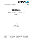
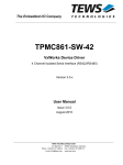
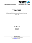
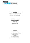
The Embedded I/O Company
TPMC861
4 Channel Isolated Serial Interface
RS422/RS485
Version 1.0
User Manual
Issue 1.0.4
November 2010
TEWS TECHNOLOGIES GmbH
Am Bahnhof 7 25469 Halstenbek, Germany
Phone: +49 (0) 4101 4058 0 Fax: +49 (0) 4101 4058 19
e-mail: [email protected] www.tews.com
TPMC861-10
4 channel isolated serial interface RS422/RS485
This document contains information, which is
proprietary to TEWS TECHNOLOGIES GmbH. Any
reproduction without written permission is forbidden.
TEWS TECHNOLOGIES GmbH has made any
effort to ensure that this manual is accurate and
complete. However TEWS TECHNOLOGIES GmbH
reserves the right to change the product described
in this document at any time without notice.
TEWS TECHNOLOGIES GmbH is not liable for any
damage arising out of the application or use of the
device described herein.
Style Conventions
Hexadecimal characters are specified with prefix 0x,
i.e. 0x029E (that means hexadecimal value 029E).
For signals on hardware products, an ‚Active Low’ is
represented by the signal name with # following, i.e.
IP_RESET#.
Access terms are described as:
W
Write Only
R
Read Only
R/W
Read/Write
R/C
Read/Clear
R/S
Read/Set
©2001-2010 by TEWS TECHNOLOGIES GmbH
All trademarks mentioned are property of their respective owners.
TPMC861 User Manual Issue 1.0.4
Page 2 of 22
Issue
Description
Date
1.0
First Issue
July 2001
1.1
Correction Figure “PCI Header”
April 2003
1.2
New address TEWS LLC
September 2006
1.0.3
New User Manual Issue Notation
“Interrupt Status Register” at PCI Base-Address 2 + 0x24
renamed to “Interrupt Pending Register”
July 2009
1.0.4
Correction Figure “Serial Channel Interface Overview”
November 2010
TPMC861 User Manual Issue 1.0.4
Page 3 of 22
Table of Contents
1
2
3
PRODUCT DESCRIPTION ......................................................................................... 6
TECHNICAL SPECIFICATION................................................................................... 7
LOCAL SPACE ADDRESSING.................................................................................. 8
3.1 PCI9030 Local Space Configuration .............................................................................................8
3.2 Local I/O Space ...............................................................................................................................8
3.3 Local Memory Space ......................................................................................................................8
3.3.1 Register Map........................................................................................................................8
3.3.2 Register Set of each channel...............................................................................................9
3.3.3 Special Registers ...............................................................................................................10
3.3.3.1 FIFO Ready Register Channel 0-3.............................................................................10
3.3.3.2 Interrupt Status Register.............................................................................................11
4
PCI9030 TARGET CHIP........................................................................................... 12
4.1 PCI Configuration Registers (PCR) .............................................................................................12
4.1.1 PCI9030 Header ................................................................................................................12
4.1.2 PCI Base Address Initialization..........................................................................................13
4.2 Local Configuration Register (LCR)............................................................................................14
4.3 Configuration EEPROM ................................................................................................................15
4.4 Local Software Reset....................................................................................................................15
5
CONFIGURATION HINTS ........................................................................................ 16
5.1 PCI Interrupt Control / Status ......................................................................................................16
6
PROGRAMMING HINTS .......................................................................................... 17
6.1 Baud Rate Programming Formula...............................................................................................17
7
INSTALLATION........................................................................................................ 18
7.1
7.2
7.3
7.4
8
Serial Channel Interface Overview ..............................................................................................18
Serial Channel Interface Configuration ......................................................................................19
DIP Switch Locations....................................................................................................................20
Default Configuration ...................................................................................................................20
PIN ASSIGNMENT – I/O CONNECTOR .................................................................. 21
8.1 Mezzanine Card I/O Connector P14.............................................................................................21
8.2 Front panel DB25 Connector .......................................................................................................22
TPMC861 User Manual Issue 1.0.4
Page 4 of 22
List of Figures
FIGURE 1-1 : BLOCK DIAGRAM......................................................................................................................6
FIGURE 7-1 : SERIAL CHANNEL INTERFACE OVERVIEW.........................................................................18
FIGURE 7-2 : DIP SWITCH LOCATIONS.......................................................................................................20
List of Tables
TABLE 2-1 : TECHNICAL SPECIFICATION.....................................................................................................7
TABLE 3-1 : PCI9030 LOCAL SPACE CONFIGURATION ..............................................................................8
TABLE 3-2 : REGISTER SET 1 ........................................................................................................................9
TABLE 3-3 : REGISTER SET 2 ........................................................................................................................9
TABLE 3-4 : SPECIAL REGISTER .................................................................................................................10
TABLE 3-5 : FIFO READY REGISTER CHANNEL 0-3 ..................................................................................10
TABLE 3-6 : INTERRUPT PENDING REGISTER (ADDRESS 0X24)............................................................11
TABLE 4-1 : PCI9030 HEADER......................................................................................................................12
TABLE 4-2 : PCI9030 BASE ADDRESS USAGE ...........................................................................................13
TABLE 4-3 : PCI9030 LOCAL CONFIGURATION REGISTER ......................................................................14
TABLE 4-4 : CONFIGURATION EEPROM .....................................................................................................15
TABLE 5-1 : INTERRUPT CONTROL/STATUS REGISTER (INTCSR, PCI BASE ADDRESS 0 + 0X4C) ...16
TABLE 6-1 : BAUD RATE PROGRAMMING TABLE......................................................................................17
TABLE 7-1 : DIP SWITCH FUNCTION ...........................................................................................................19
TABLE 7-2 : DIP SWITCH CONFIGURATION ...............................................................................................19
TABLE 8-1 : MEZZANINE CARD I/O CONNECTOR P14 ..............................................................................21
TABLE 8-2 : FRONT PANEL DB25 FEMALE CONNECTOR.........................................................................22
TPMC861 User Manual Issue 1.0.4
Page 5 of 22
1 Product Description
The TPMC861 is a standard single-width 32 bit PMC module with four channels of high performance
RS422/485-HD/FD serial interface. Each of the four channels is isolated from the system and against
each other by optocoupler and on board DC/DC converter per channel.
The serial channels are accessible through a DB25 connector mounted in the front panel and via P14
I/O. Each channel has a 128 byte transmit FIFO and a 128 byte receive FIFO to significantly reduce
the overhead required to provide data to and get data from the transmitter and receivers. The FIFO
trigger levels are programmable. For RS422 and RS485-FD a four wire interface (RX+, RX-, TX+, TX-)
plus isolated ground (GND) per channel is supported. For RS485-HD a two wire interface (DX+, DX-)
plus isolated ground (GND) per channel is supported. The baud rate is individually programmable up
to 460.8 Kbaud for each channel. The interrupts are supported.
All channels generate interrupts on PCI interrupt INTA. For fast interrupt source detection the
TPMC861 provides a special interrupt pending register.
Each receiver input and transmitter output of all channels is protected against electrostatic discharge
(ESD) up to +/- 15kV according to IEC 1000-4-2.
Figure 1-1 : Block Diagram
TPMC861 User Manual Issue 1.0.4
Page 6 of 22
2 Technical Specification
PMC Interface
Mechanical Interface
PCI Mezzanine Card (PMC) Interface
Single Size
Electrical Interface
PCI Rev. 2.1 compliant
33 MHz / 32 bit PCI
3.3V and 5V PCI Signaling Voltage
On Board Devices
PCI Target Chip
PCI9030 (PLX Technology)
UART Controller
XR16C864 (4 channel UART, RS422/RS485)
I/O Interface
Number of UART Channels
4
FIFO
128byte transmit FIFO, 128byte receive FIFO per channel
Interrupts
PCI INTA for all channels, on board Interrupt Pending Register
I/O Signals / Channel
TX+/-, RX+/-, isolated GND
Maximum Transfer Rate
Each channel programmable up to 460.8 kbaud
ESD Protection
+/- 15kV Human Body Model, +/- 6kV IEC1000-4-2 Model
I/O Connector
DB25 female connector
PMC P14 I/O (64 pin Mezzanine connector)
Physical Data
Power Requirements
33mA typical @+3.3V DC
246mA typical @+5V DC
Temperature Range
Operating
Storage
MTBF
210613 h
Humidity
5 – 95 % non-condensing
Weight
85 g
-40°C to +85 °C
-55°C to +125°C
Table 2-1 : Technical Specification
TPMC861 User Manual Issue 1.0.4
Page 7 of 22
3 Local Space Addressing
3.1 PCI9030 Local Space Configuration
The local on board addressable regions are accessed from the PCI side by using the PCI9030 local
spaces.
PCI9030
Local
Space
PCI9030
PCI Base Address
(Offset in PCI
Configuration
Space)
PCI
Space
Mapping
Size
(Byte)
Port
Width
(Bit)
Endian
Mode
Description
0
0x18
MEM
64
8
Little
Access of all
TPMC861 register
Table 3-1 : PCI9030 Local Space Configuration
3.2 Local I/O Space
Not used by the TPMC861.
3.3 Local Memory Space
All local registers of the TPMC861 are accessible in the memory space of the PMC module.
Address range: PCI Base Address 2 for Local Address Space 0 + (0x00 to 0x24).
UART controller channel 0:
PCI Base Address 2 + (x000 to 0x07)
UART controller channel 1:
PCI Base Address 2 + (0x08 to 0x0F)
UART controller channel 2:
PCI Base Address 2 + (0x10 to 0x17)
UART controller channel 3:
PCI Base Address 2 + (0x18 to 0x1F)
FIFO Ready Register CH0-CH3:
PCI Base Address 2 + (0x20)
Interrupt Pending Register:
PCI Base Address 2 + (0x24)
PCI Base Address:
PCI9030 PCI Base Address 2 (Offset 0x18 in PCI Configuration Space).
3.3.1 Register Map
Each of the four isolated serial channels of the TPMC861 is accessed in the PCI Memory Space by
two sets of registers. Both register sets have a common register, the Line Control Register (LCR). Bit 7
of the Control Register is used to switch between the two register sets of a channel.
TPMC861 User Manual Issue 1.0.4
Page 8 of 22
3.3.2 Register Set of each channel
Register Set 1 is only accessible if bit 7 of the Line Control Register (LCR, Address: PCI Base Address
2 + Channel Offset + 0x03) is set to ‘0’. After reset Register Set 1 is accessible.
PCI Base Address +
Channel Offset +
Read Mode
Write Mode
Size
0x00
Receive Holding Register
Transmit Holding Register
Byte
0x01
Interrupt Enable Register
Interrupt Enable Register
Byte
0x02
Interrupt Status Register
FIFO Control Register
Byte
0x03
Line Control Register
Line Control Register
Byte
0x04
Modem Control Register
Modem Control Register
Byte
0x05
Line Status Register (LCR)
-
Byte
0x06
Modem Status Register
-
Byte
0x07
Scratchpad Register
Scratchpad Register
Byte
Table 3-2 : Register Set 1
To get to the first two registers of Register Set 2, bit 7 of the Line Control Register must be set to ‘1’.
PCI Base Address +
Channel Offset +
READ/WRITE
Size
Comment
0x00
LSB of Divisor Latch
Byte
LCR bit-7 set to ‘1’
0x01
MSB of Divisor Latch
Byte
LCR bit-7 set to ‘1’
The Enhanced Feature Registers, Xon-1/2 and Xoff-1/2 registers are only accessible if the LCR is set
to ‘0xBF’.
PCI Base Address +
Channel Offset +
READ/WRITE
Size
Comment
0x00
Trigger Level Register (TRG)
Byte
LCR is set to ‘0xBF’
0x01
Feature Control Register (FCTR)
Byte
LCR is set to ‘0xBF’
0x02
Enhanced Feature Register (EFR)
Byte
LCR is set to ‘0xBF’
0x03
Line Control Register (LCR)
Byte
Always accessible
0x04
Xon-1 Word
Byte
LCR is set to ‘0xBF’
0x05
Xon-2 Word
Byte
LCR is set to ‘0xBF’
0x06
Xoff-1 Word
Byte
LCR is set to ‘0xBF’
0x07
Xoff-2 Word
Byte
LCR is set to ‘0xBF’
Table 3-3 : Register Set 2
When LCR is set to ‘0xBF’ and FCTR bit 6 is set to ‘1’, the EMS Register is accessible:
PCI Base Address +
Channel Offset +
READ/WRITE
Size
Comment
0x07
Enhanced Mode Select Register
(EMSR)
Byte
LCR is set to ‘0xBF’
TPMC861 User Manual Issue 1.0.4
Page 9 of 22
3.3.3 Special Registers
The TPMC861 provides two special registers. For fast status detection there is a FIFO Ready Register
for channel 0 to channel 3 and an Interrupt Pending Register for all four channels.
Offset to PCI
Base Address 2
Register Name
Size
(Bit)
0x20
FIFO Ready Register Channel 0 - Channel 3
8
0x24
Interrupt Pending Register
8
Table 3-4 : Special Register
3.3.3.1 FIFO Ready Register Channel 0-3
The FIFO Ready Register FIFORDY1 is a byte wide read only register. The FIFO Ready Register
provides the status of the transmit and receive FIFO’s of channel 0 to channel 3. Each TX and RX
channel (0-3) has its own 128 byte FIFO. When any of the TX/RX FIFO’s become empty/full, the
status bit associated with the TX/RX function of channel 0-3 is set in the FIFO Ready Register.
Bit
Symbol
7
RXRDY
Channel 3
6
RXRDY
Channel 2
5
RXRDY
Channel 1
4
RXRDY
Channel 0
3
TXRDY
Channel 3
2
TXRDY
Channel 2
1
TXRDY
Channel 1
0
TXRDY
Channel 0
Description
RX Ready Bit for channel 0-3
0 = the corresponding receive FIFO is above the programmed
trigger level or a time-out has occurred
1 = the receiver is ready and is below the programmed trigger
level
TX Ready Bit for channel 0-3
0 = the corresponding transmit FIFO is full. This channel will not
accept any more transmit data
1 = one or more empty locations exist in the corresponding
FIFO
Access
Reset
Value
R
R
Table 3-5 : FIFO Ready Register Channel 0-3
TPMC861 User Manual Issue 1.0.4
Page 10 of 22
3.3.3.2 Interrupt Pending Register
The Interrupt Pending Register is a byte wide read only register located in the PCI Memory Space
(PCI Base Address2 + 0x24) and reflects the interrupt status of the four UART channels. It is useful for
fast interrupt source detection.
Bit
Symbol
7:4
3
Interrupt
Channel 3
2
Interrupt
Channel 2
1
Interrupt
Channel 1
0
Interrupt
Channel 0
Description
Access
Reset
Value
Not used
-
-
R
0x0
Interrupt Status of Channel 0-3
1 = indicates interrupt is pending on channel 0-3
0 = no interrupt on channel 0-3
Table 3-6 : Interrupt Pending Register (Address 0x24)
Each of the four serial channels generates interrupts on the local interrupt 1 of the PCI target chip,
which is mapped to PCI interrupt INTA.
If the “PCI Interrupt Enable” of the PCI target chip is disabled (INTCSR bit 6 is set to ‘0’) the Interrupt
Pending Register can be used as a polling register for interrupts of the four serial channels.
Interrupts from the four serial channels can be individual enabled by the ST16C654 serial controller.
After reset all UART interrupts are disabled.
TPMC861 User Manual Issue 1.0.4
Page 11 of 22
4 PCI9030 Target Chip
4.1 PCI Configuration Registers (PCR)
4.1.1 PCI9030 Header
PCI CFG
Register
Address
Write ‘0’ to all unused (Reserved) bits
31
24
23
16
15
PCI
Initial Values
writeable (Hex Values)
8
7
0
0x00
Device ID
Vendor ID
N
035D 1498
0x04
Status
Command
Y
0280 0000
Revision ID
N
070200 0A
Cache Line
Size
Y[7:0]
00 00 00 00
0x08
0x0C
Class Code
BIST
Header Type
PCI Latency
Timer
0x10
PCI Base Address 0 for MEM Mapped Config. Registers
Y
FFFFFF80
0x14
PCI Base Address 1 for I/O Mapped Config. Registers
Y
FFFFFF81
0x18
PCI Base Address 2 for Local Address Space 0
Y
FFFFFFC0
0x1C
PCI Base Address 3 for Local Address Space 1
Y
00000000
0x20
PCI Base Address 4 for Local Address Space 2
Y
00000000
0x24
PCI Base Address 5 for Local Address Space 3
Y
00000000
0x28
PCI CardBus Information Structure Pointer
N
00000000
N
000A 1498
Y
00000000
N
000000 40
N
00000000
00 00 01 00
0x2C
Subsystem ID
0x30
PCI Base Address for Local Expansion ROM
0x34
Reserved
0x38
0x3C
Subsystem Vendor ID
Max_Lat
0x40
Min_Gnt
PM Cap.
0x44
PM Data
PM CSR EXT
0x48
Reserved
HS CSR
0x4C
New Cap. Ptr.
Reserved
VPD Address
0x50
Interrupt Pin
Interrupt Line
Y[7:0]
PM Nxt Cap.
PM Cap. ID
N
4801 48 01
Y
00 00 0000
PM CSR
HS Nxt Cap.
HS Cap. ID
Y[23:16]
00 00 4C 06
VPD Nxt Cap.
VPD Cap. ID
Y[31:16]
0000 00 03
Y
00000000
VPD Data
Table 4-1 : PCI9030 Header
TPMC861 User Manual Issue 1.0.4
Page 12 of 22
4.1.2 PCI Base Address Initialization
PCI Base Address Initialization is scope of the PCI host software.
PCI9030 PCI Base Address Initialization:
1. Write 0xFFFF_FFFF to the PCI9030 PCI Base Address Register.
2. Read back the PCI9030 PCI Base Address Register.
3. For PCI Base Address Registers 0:5, check bit 0 for PCI Address Space.
Bit 0 = '0' requires PCI Memory Space mapping
Bit 0 = '1' requires PCI I/O Space mapping
For the PCI Expansion ROM Base Address Register, check bit 0 for usage.
Bit 0 = ‘0’: Expansion ROM not used
Bit 0 = ‘1’: Expansion ROM used
4. For PCI I/O Space mapping, starting at bit location 2, the first bit set determines the size of the
required PCI I/O Space size.
For PCI Memory Space mapping, starting at bit location 4, the first bit set to '1' determines the size
of the required PCI Memory Space size.
For PCI Expansion ROM mapping, starting at bit location 11, the first bit set to '1' determines the
required PCI Expansion ROM size.
For example, if bit 5 of a PCI Base Address Register is detected as the first bit set to ‘1’, the
PCI9030 is requesting a 32 byte space (address bits 4:0 are not part of base address decoding).
5. Determine the base address and write the base address to the PCI9030 PCI Base Address
Register. For PCI Memory Space mapping the mapped address region must comply with the
definition of bits 3:1 of the PCI9030 PCI Base Address Register.
After programming the PCI9030 PCI Base Address Registers, the software must enable the
PCI9030 for PCI I/O and/or PCI Memory Space access in the PCI9030 PCI Command Register
(Offset 0x04). To enable PCI I/O Space access to the PCI9030, set bit 0 to '1'. To enable PCI
Memory Space access to the PCI9030, set bit 1 to '1'.
Offset in Config.
Description
Usage
0x10
PCI9030 LCR’s MEM
Used
0x14
PCI9030 LCR’s I/O
Used
0x18
PCI9030 Local Space 0
Used
Table 4-2 : PCI9030 Base Address Usage
TPMC861 User Manual Issue 1.0.4
Page 13 of 22
4.2 Local Configuration Register (LCR)
After reset, the PCI9030 Local Configuration Registers are loaded from the on board serial
configuration EEPROM.
The PCI base address for the PCI9030 Local Configuration Registers is PCI9030 PCI Base
Address 0 (PCI Memory Space, Offset 0x10 in the PCI9030 PCI Configuration Register Space)
or PCI9030 PCI Base Address 1 (PCI I/O Space, Offset 0x14 in the PCI9030 PCI Configuration
Register Space).
Do not change hardware dependent bit settings in the PCI9030 Local Configuration Registers.
Offset from
PCI Base
Address
Register
Value
Description
0x00
Local Address Space 0 Range
0x0FFF_FFC0
Used memory space
0x04
Local Address Space 1 Range
0x0000_0000
Not used
0x08
Local Address Space 2 Range
0x0000_0000
Not used
0x0C
Local Address Space 3 Range
0x0000_0000
Not used
0x10
Local Exp. ROM Range
0x0000_0000
Not used
0x14
Local Re-map Register Space 0
0x0000_0001
Address Offset for Memory
0x18
Local Re-map Register Space 1
0x0000_0000
Not used
0x1C
Local Re-map Register Space 2
0x0000_0000
Not used
0x20
Local Re-map Register Space 3
0x0000_0000
Not used
0x24
Local Re-map Register ROM
0x0000_0000
Not used
0x28
Local Address Space 0 Descriptor
0x5000_8080
Local Timing Address Space 0
0x2C
Local Address Space 1 Descriptor
0x0000_0000
Not used
0x30
Local Address Space 2 Descriptor
0x0000_0000
Not used
0x34
Local Address Space 3 Descriptor
0x0000_0000
Not used
0x38
Local Exp. ROM Descriptor
0x0000_0000
Not used
0x3C
Chip Select 0 Base Address
0x0000_0011
UART-Register
0x40
Chip Select 1 Base Address
0x0000_0027
Special Register
0x44
Chip Select 2 Base Address
0x0000_0023
Not used
0x48
Chip Select 3 Base Address
0x0000_0000
Not used
0x4C
Interrupt Control/Status
0x0041
Interrupt Configuration
0x4E
EEPROM Write Protect Boundary
0x0030
No write protection
0x50
Miscellaneous Control Register
0x0078_0000
Retry Delay = max.(reset value)
0x54
General Purpose I/O Control
0x26D2_0249
All GP I/Os are outputs
0x70
Hidden1 Power Management data
select
0x0000_0000
Not used
0x74
Hidden 2 Power Management data
scale
0x0000_0000
Not used
Table 4-3 : PCI9030 Local Configuration Register
TPMC861 User Manual Issue 1.0.4
Page 14 of 22
4.3 Configuration EEPROM
After power-on or PCI reset, the PCI9030 loads initial configuration register data from the on board
configuration EEPROM.
The configuration EEPROM contains the following configuration data:
• Address 0x00 to 0x27 : PCI9030 PCI Configuration Register Values
• Address 0x28 to 0x87 : PCI9030 Local Configuration Register Values
See the PCI9030 Manual for more information.
Address
Offset
0x00
0x02
0x04
0x06
0x08
0x0A
0x0C
0x0E
0x00
0x035D
0x1498
0x0280
0x0000
0x0702
0x000A
0x000A
0x1498
0x10
0x0000
0x0040
0x0000
0x0101
0x4801
0x4801
0x0000
0x0000
0x20
0x0000
0x4C06
0x0000
0x0003
0x0FFF
0xFFC0
0x0000
0x0000
0x30
0x0000
0x0000
0x0000
0x0000
0x0000
0x0000
0x0000
0x0001
0x40
0x0000
0x0000
0x0000
0x0000
0x0000
0x0000
0x0000
0x0000
0x50
0x5000
0x8080
0x0000
0x0000
0x0000
0x0000
0x0000
0x0000
0x60
0x0000
0x0000
0x0000
0x0011
0x0000
0x0027
0x0000
0x0023
0x70
0x0000
0x0000
0x0030
0x0041
0x0078
0x0000
0x0249
0x26D2
0x80
0x0000
0x0000
0x0000
0x0000
0xFFFF
0xFFFF
0xFFFF
0xFFFF
0x90
0xFFFF
0xFFFF
0xFFFF
0xFFFF
0xFFFF
0xFFFF
0xFFFF
0xFFFF
0xA0
0xFFFF
0xFFFF
0xFFFF
0xFFFF
0xFFFF
0xFFFF
0xFFFF
0xFFFF
0xB0
0xFFFF
0xFFFF
0xFFFF
0xFFFF
0xFFFF
0xFFFF
0xFFFF
0xFFFF
0xC0
0xFFFF
0xFFFF
0xFFFF
0xFFFF
0xFFFF
0xFFFF
0xFFFF
0xFFFF
0xD0
0xFFFF
0xFFFF
0xFFFF
0xFFFF
0xFFFF
0xFFFF
0xFFFF
0xFFFF
0xE0
0xFFFF
0xFFFF
0xFFFF
0xFFFF
0xFFFF
0xFFFF
0xFFFF
0xFFFF
0xF0
0xFFFF
0xFFFF
0xFFFF
0xFFFF
0xFFFF
0xFFFF
0xFFFF
0xFFFF
Table 4-4 : Configuration EEPROM
4.4 Local Software Reset
The PCI9030 Local Reset Output LRESETo# is used to reset the on board local logic.
The PCI9030 local reset is active during PCI reset or if the PCI Adapter Software Reset bit is set in the
PCI9030 local configuration register CNTRL (offset 0x50).
CNTRL[30] PCI Adapter Software Reset:
Value of 1 resets the PCI9030 and issues a reset to the Local Bus (LRESETo# asserted). The
PCI9030 remains in this reset condition until the PCI Host clears this bit. The contents of the PCI9030
PCI and Local Configuration Registers are not reset. The PCI9030 PCI Interface is not reset.
TPMC861 User Manual Issue 1.0.4
Page 15 of 22
5 Configuration Hints
5.1 PCI Interrupt Control / Status
The UART generates an interrupt on pin INTA# of the PCI bus. The interrupt status can be read at the
Interrupt Status Register INTCSR of the PCI Controller PCI9030.
Bit
Symbol
Description
Access
Reset
Value
Not used
R
0
Software Interrupt
R/W
0
31:8
-
7
SINT
6
PINT Enable
PCI Interrupt Enable
R/W
1
5
LINT2 Status
Local Interrupt 2 Status (not in use)
R
0
4
LINT2 Polarity
Local Interrupt 2 Polarity
R/W
0
3
LINT2 Enable
Local Interrupt 2 Enable
R/W
0
2
LINT1 Status
Local Interrupt Status (UART)
R
0
1
LINT1 Polarity
Local Interrupt 1 Polarity
R/W
0
0
LINT1 Enable
Local Interrupt 1 Enable
R/W
1
Table 5-1 : Interrupt Control/Status Register (INTCSR, PCI Base Address 0 + 0x4C)
This register will be initialized from the on board EEPROM after power-on with the above shown initial
values.
The local interrupt 1 reflects the four channel UART interrupts. Bit 2 will be set if bit 0 is set and an
interrupt is generated on one or more UART channels. For more information see chapter “Interrupt
Pending Register”.
TPMC861 User Manual Issue 1.0.4
Page 16 of 22
6 Programming Hints
6.1 Baud Rate Programming Formula
Each of the four serial isolated channels of the TPMC861 contains a programmable baud rate
generator. The clock of the ST16C654 can divided by any divisor from 1 to 216 – 1. The divisor can be
programmed by the LSB and the MSB of the Divisor Latch Register. After reset the MCR bit 7 of each
channel is default ‘0’ and the value of LSB and MSB is 0xFFFF.
The basic formula of baud rate programming is:
7.3728MHz
16 * DIVISOR * (1 + 3 * MCR _ BIT 7)
Baud Rate
MCR bit 7=0
Baud Rate
MCR bit 7=1
Divisor
200
50
0x0900
300
75
0x0600
600
150
0x0300
1200
300
0x0180
2400
600
0x00C0
4800
1200
0x0060
9600
2400
0x0030
19.2K
4800
0x0018
28.8K
7200
0x0010
38.4K
9600
0x000C
76.8K
19.2K
0x0006
153.6K
38.4K
0x0003
230.4K
57.6K
0x0002
460.8K
115.2K
0x0001
Table 6-1 : Baud Rate Programming Table
TPMC861 User Manual Issue 1.0.4
Page 17 of 22
7 Installation
7.1 Serial Channel Interface Overview
Figure below shows the hardware scheme of the TPMC861 serial channel interfaces.
+5V Isolated
UART
Optocouoler
Transceiver
Connector
TXD+, DX+
Tx
TXD-, DX+5V Isolated
120
Sx-6
Sx-10
+5V
Sx-4
Sx-3
1k5
120
Sx-9
Full / Half Duplex
OP1
+5V Isolated
1k5
Sx-5
+5V Isolated
Half Dupl.
Rx / Tx
Select
RI#
Termination
Sx-8
Isolated
Isolated
Rx
Sx-1
Sx-2
RXD+
RXD-
Figure 7-1 : Serial Channel Interface Overview
TPMC861 User Manual Issue 1.0.4
Page 18 of 22
7.2 Serial Channel Interface Configuration
The isolated serial channel interface is configurable by DIP switch for each channel individually. There
is a 10 switch DIP switch for each of the 4 isolated serial channels.
Sx-y with x =1 to 4 channel and y = 1 to 10 is switch number y on the DIP switch for serial channel x.
Sub Switch ID
Function Group
Function
Sx-1, Sx-2
Duplex Mode Configuration 1
ON: RS422 and RS485 FD Modes
OFF: RS485 HD Mode
Sx-3, Sx-4
Duplex Mode Configuration 2
ON: RS485 HD Mode
OFF: RS422 and RS485 FD Modes
Sx-5
Transmitter Enable Control
ON: Controlled by 16C864
OFF: Transmitter Enabled
Sx-6
Receiver Enable Control
ON: Controlled by 16C864
OFF: Receiver Enabled
Sx-7
Reserved
Sx-8
Transmit Line Termination
ON: 120R Transmit Line Termination
OFF: No Transmit Line Termination
Sx-9, Sx-10
Receive Line Termination
ON: 120R Receive Line Termination
OFF: No Receive Line Termination
FD: Full Duplex, HD: Half Duplex
Table 7-1 : DIP Switch Function
RS422
Sx-1
Sx-2
Sx-3
Sx-4
Sx-5
Sx-6
Sx-7
Sx-8
Sx-9
Sx-10
Sx-8
Sx-9
Sx-10
Sx-8
Sx-9
Sx-10
Sx-8
Sx-9
Sx-10
X
RS485 FD-M
Sx-1
Sx-2
Sx-3
Sx-4
Sx-5
Sx-6
Sx-7
X
RS485 FD-S
Sx-1
Sx-2
Sx-3
Sx-4
Sx-5
Sx-6
Sx-7
X
RS485 HD
Sx-1
Sx-2
Sx-3
Sx-4
Sx-5
Sx-6
Sx-7
X
Switch Closed (ON)
FD-M : Full Duplex Master
FD-S : Full Duplex Slave
HD : Half Duplex
X = Reserved
Switch Open (OFF)
Switch setting depends on bus configuration
Table 7-2 : DIP Switch Configuration
TPMC861 User Manual Issue 1.0.4
Page 19 of 22
7.3 DIP Switch Locations
Figure 7-2 : DIP Switch Locations
7.4 Default Configuration
All 4 channels are configured to RS422 mode by factory default.
TPMC861 User Manual Issue 1.0.4
Page 20 of 22
8 Pin Assignment – I/O Connector
8.1 Mezzanine Card I/O Connector P14
Pin
TPMC861
RS485-HD
TPMC861
RS422
RS485-FD
Comment
1
GND_A
GND_A
Isolated Ground Channel A
2
DX0-
TXD0-
Serial Channel A
3
DX0+
TXD0+
Serial Channel A
4
RXD0-
Serial Channel A
5
RXD0+
Serial Channel A
6
GND_B
GND_B
Isolated Ground Channel B
7
DX1-
TXD1-
Serial Channel B
8
DX1+
TXD1+
Serial Channel B
9
RXD1-
Serial Channel B
10
RXD1+
Serial Channel B
11
GND_C
GND_C
Isolated Ground Channel C
12
DX2-
TXD2-
Serial Channel C
13
DX2+
TXD2+
Serial Channel C
14
RXD2-
Serial Channel C
15
RXD2+
Serial Channel C
16
GND_D
GND_D
Isolated Ground Channel D
17
DX3-
TXD3-
Serial Channel D
18
DX3+
TXD3+
Serial Channel D
19
RXD3-
Serial Channel D
20
RXD3+
Serial Channel D
NC
Not connected
21..64
NC
Table 8-1 : Mezzanine Card I/O Connector P14
TPMC861 User Manual Issue 1.0.4
Page 21 of 22
8.2 Front panel DB25 Connector
Pin
TPMC861
RS485-HD
TPMC861
RS422
RS485-FD
Comment
1
DX0-
TXD0-
Serial Channel A
2
DX0+
TXD0+
Serial Channel A
3
GND_A
GND_A
Isolated Ground Channel A
4
DX1-
TXD1-
Serial Channel B
5
DX1+
TXD1+
Serial Channel B
6
GND_B
GND_B
Isolated Ground Channel B
7
DX2-
TXD2-
Serial Channel C
8
DX2+
TXD2+
Serial Channel C
9
GND_C
GND_C
Isolated Ground Channel C
10
DX3-
TXD3-
Serial Channel D
11
DX3+
TXD3+
Serial Channel D
12
GND_D
GND_D
Isolated Ground Channel D
13
NC
NC
Not connected
14
RXD0-
Serial Channel A
15
RXD0+
Serial Channel A
GND_A
Isolated Ground Channel A
17
RXD1-
Serial Channel B
18
RXD1+
Serial Channel B
GND_B
Isolated Ground Channel B
20
RXD2-
Serial Channel C
21
RXD2+
Serial Channel C
GND_C
Isolated Ground Channel C
23
RXD3-
Serial Channel D
24
RXD3+
Serial Channel D
GND_D
Isolated Ground Channel D
16
19
22
25
GND_A
GND_B
GND_C
GND_D
Table 8-2 : Front panel DB25 female connector
TPMC861 User Manual Issue 1.0.4
Page 22 of 22