1
User’s Manual Pub. 0300257-01 Rev. A
Point IO™
2/4 Channel Analog HART Module
Catalog Number: 1734sc-IE2CH / IE4CH
ii
Point IO™ 2/4 Channel Analog HART Module
Important Notes
1.
Please read all the information in this owner’s guide before installing the
product.
2.
The information in this owner's guide applies to hardware Series A and firmware
version 1.00 or later.
3.
This guide assumes that the reader has a full working knowledge of the relevant
processor.
Notice
The products and services described in this owner's guide are useful in a wide variety of
applications. Therefore, the user and others responsible for applying the products and
services described herein are responsible for determining their acceptability for each
application. While efforts have been made to provide accurate information within this
owner's guide, Spectrum Controls assumes no responsibility for the accuracy,
completeness, or usefulness of the information herein.
Under no circumstances will Spectrum Controls be responsible or liable for any damages
or losses, including indirect or consequential damages or losses, arising out of either the
use of any information within this owner's guide or the use of any product or service
referenced herein.
No patent liability is assumed by Spectrum Controls with respect to the use of any of the
information, products, circuits, programming, or services referenced herein.
The information in this owner's guide is subject to change without notice.
Limited Warranty
Spectrum Controls warrants that its products are free from defects in material and
workmanship under normal use and service, as described in Spectrum Controls literature
covering this product, for a period of 1 year. The obligations of Spectrum Controls under
this warranty are limited to replacing or repairing, at its option, at its factory or facility,
any product which shall, in the applicable period after shipment, be returned to the
Spectrum Controls facility, transportation charges prepaid, and which after examination
is determined, to the satisfaction of Spectrum Controls, to be thus defective.
This warranty shall not apply to any such equipment which shall have been repaired or
altered except by Spectrum Controls or which shall have been subject to misuse, neglect,
or accident. In no case shall the liability of Spectrum Controls exceed the purchase price.
The aforementioned provisions do not extend the original warranty period of any product
which has either been repaired or replaced by Spectrum Controls.
User’s Manual Pub. 0300257-01 Rev. A
iii
Table of Contents
IMPORTANT NOTES ............................................................................................................................................... II
NOTICE .................................................................................................................................................................. II
LIMITED WARRANTY .............................................................................................................................................. II
CHAPTER 1 MODULE OVERVIEW ......................................................................................................................... 1-1
SECTION 1.1 GENERAL DESCRIPTION .............................................................................................................................. 1-1
SECTION 1.2 INPUT TYPES ............................................................................................................................................ 1-1
SECTION 1.3 DATA FORMATS ....................................................................................................................................... 1-1
SECTION 1.4 FILTER FREQUENCIES ................................................................................................................................ 1-1
SECTION 1.5 HARDWARE FEATURES .............................................................................................................................. 1-2
1.5.1 LED Indicators ........................................................................................................................................... 1-3
SECTION 1.6 SYSTEM OVERVIEW ................................................................................................................................... 1-3
1.6.1 Module Power-up ..................................................................................................................................... 1-3
1.6.2 Module Operation..................................................................................................................................... 1-4
CHAPTER 2 INSTALLATION AND WIRING ............................................................................................................. 2-1
SECTION 2.1 COMPLIANCE TO EUROPEAN UNION DIRECTIVES ............................................................................................. 2-1
2.1.1 EMC Directive............................................................................................................................................ 2-1
2.1.2 Low Voltage Directive ............................................................................................................................... 2-1
SECTION 2.2 POWER REQUIREMENTS ............................................................................................................................ 2-1
SECTION 2.3 GENERAL CONSIDERATIONS ........................................................................................................................ 2-2
2.3.1 Hazardous Location Considerations .......................................................................................................... 2-2
2.3.2 Prevent Electrostatic Discharge ................................................................................................................ 2-3
2.3.3 Remove Power .......................................................................................................................................... 2-3
2.3.4 Selecting a Location .................................................................................................................................. 2-3
SECTION 2.4 MOUNTING ............................................................................................................................................. 2-3
2.4.1 Before You Begin ....................................................................................................................................... 2-3
2.4.2 Install Mounting Base ............................................................................................................................... 2-5
2.4.3 Install the I/O Module ............................................................................................................................... 2-5
2.4.4 Install the Removable Terminal Block (RTB) ............................................................................................. 2-6
2.4.5 Remove a Mounting Base ......................................................................................................................... 2-6
2.4.6 Install a 1734-TOPS Base .......................................................................................................................... 2-7
2.4.7 Remove a 1734-TOPS Base ....................................................................................................................... 2-7
SECTION 2.5 FIELD WIRING CONNECTIONS...................................................................................................................... 2-7
2.5.1 Wiring Diagram ........................................................................................................................................ 2-8
CHAPTER 3 CONFIGURING THE 1734SC-IEXCH USING RSLOGIX 5000 .................................................................. 3-1
SECTION 3.1 INTRODUCTION ........................................................................................................................................ 3-1
SECTION 3.2 ABOUT COMMUNICATIONS......................................................................................................................... 3-1
SECTION 3.3 USE GENERIC PROFILE ............................................................................................................................... 3-2
3.3.1 Add a Local Ethernet Bridge Module ........................................................................................................ 3-2
3.3.2 Add a Remote Ethernet Point IO Adapter ................................................................................................. 3-4
3.3.3 Add the Generic Point IO Module ............................................................................................................. 3-5
SECTION 3.4 USE ADD-ON-PROFILE.............................................................................................................................. 3-7
3.4.1 Installing The Add-On profile .................................................................................................................... 3-7
3.4.2 Adding the IExCH Module To Your Logix Project....................................................................................... 3-8
SECTION 3.5 MODULE CONFIGURATION......................................................................................................................... 3-9
3.5.1 Channel Configuration ............................................................................................................................ 3-11
3.5.2 Analog Notch Filter ................................................................................................................................. 3-13
3.5.3 RTS (Real Time Sample) .......................................................................................................................... 3-13
3.5.4 HART Pass-through Handle Timeout....................................................................................................... 3-14
SECTION 3.6 READ INPUT DATA ................................................................................................................................. 3-14
User’s Manual Pub. 0300257-01 Rev. A
iv
Point IO™ 2/4 Channel Analog HART Module
SECTION 3.7 MODULE UPDATE TIME ........................................................................................................................... 3-18
CHAPTER 4 IEXCH AND HART .............................................................................................................................. 4-1
SECTION 4.1 HART FEATURES ...................................................................................................................................... 4-1
SECTION 4.2 DETECTING HART DEVICES ........................................................................................................................ 4-1
4.2.1 Auto-Scanning of Dynamic HART Variables (PV, SV, TV, FV) .................................................................... 4-3
SECTION 4.3 SUPPORTED HART CIP MESSAGES .............................................................................................................. 4-4
4.3.1 Read Additional Device Status .................................................................................................................. 4-4
4.3.2 Get HART Device Information ................................................................................................................... 4-6
4.3.3 HART Pass-through Messaging ................................................................................................................. 4-9
4.3.4 Flush Queue ............................................................................................................................................ 4-14
4.3.5 Suspend HART Communication............................................................................................................... 4-14
4.3.6 Resume HART Communication ............................................................................................................... 4-15
APPENDIX A MODULE SPECIFICATIONS ...............................................................................................................A-1
APPENDIX B ADDITIONAL HART PROTOCOL INFORMATION ............................................................................... B-1
SECTION B.1 MESSAGE STRUCTURE ............................................................................................................................... B-1
B.1.1 Master-slave Operation ............................................................................................................................ B-1
B.1.2 Multiple Master Operation ....................................................................................................................... B-1
B.1.3 Transaction Procedure .............................................................................................................................. B-2
B.1.4 Burst Mode ............................................................................................................................................... B-2
SECTION B.2 RESPONSE CODE AND FIELD DEVICE STATUS .................................................................................................. B-2
SECTION B.3 HART PV, SV, TV, AND FV STATUS ............................................................................................................ B-9
APPENDIX C MANUFACTURER IDENTIFICATION CODES ...................................................................................... C-1
APPENDIX D ENGINEERING UNIT CODES ............................................................................................................ D-1
User’s Manual Pub. 0300257-01 Rev. A
v
PREFACE
Read this preface to familiarize yourself with the rest of the manual. This preface covers
the following topics:
•
•
•
•
•
Who should use this manual
How to use this manual
Related publications
Conventions used in this manual
Rockwell Automation support
Who Should
Use This Manual
Use this manual if you are responsible for designing, installing, programming, or
troubleshooting control systems that use Allen-Bradley I/O and/or compatible controllers,
such as CompactLogix and ControlLogix.
How to Use
This Manual
As much as possible, we organized this manual to explain, in a task-by-task manner, how
to install, configure, program, operate and troubleshoot a control system using the
1734sc-IExCH.
Related
Documentation
The table below provides a listing of publications that contain important information
about Allen-Bradley PLC systems.
For
A description and
overview of the 1734 and
1734D series POINT I/O
modules
and compatible control
platforms. Also includes
an overview of how to
specify
a POINT I/O system.
Information about how to
install the 1734-EP24DC,
Series B POINT I/O 24V
dc Expansion Power
Supply.
Information about how to
install 1734-TB and -TBS
POINT I/O Wiring Base
Assemblies
Information about how to
install 1734-TB3 and TB3S POINT I/O Wiring
Base
Assemblies.
Refer to this
Document
POINT I/O Selection
Guide
Allen-Bradley
Pub. No.
1734-SG001
Expansion Power
Supply Installation
Instructions
1734-IN058
Wiring Base Assembly
Installation Instructions
1734-IN511
Wiring Base Assembly
Installation Instructions
1734-IN013
If you would like a manual, you can:
• Download a free electronic version from the internet at
www.theautomationbookstore.com
• Purchase a printed manual by:
o Contacting your local distributor or Rockwell Automation
representative
o Visiting www.theautomationbookstore.com and placing your order
User’s Manual Pub. 0300257-01 Rev. A
vi
Point IO™ 2/4 Channel Analog HART Module
o
Calling 1.800.963.9548 (USA/Canada) or 001.330.725.1574
(Outside USA/Canada)
User’s Manual Pub. 0300257-01 Rev. A
vii
Conventions
Used in This
Manual
The following conventions are used throughout this manual:
• Bulleted lists (like this one) provide information not procedural steps.
• Numbered lists provide sequential steps or hierarchical information.
• Italic type is used for emphasis
• Bold type identifies headings and sub-headings
!
•
Attention Are used to identify critical information to the reader
User’s Manual Pub. 0300257-01 Rev. A
viii
Point IO™ 2/4 Channel Analog HART Module
User’s Manual Pub. 0300257-01 Rev. A
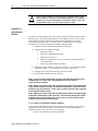
Chapter 1
Module Overview
The 1734sc-IE2CH module has two analog input channels with HART and the IE4CH
has four. Each channel on either module can be configured for current only or current
with HART. This chapter includes information about:
•
General description
•
Input types
•
Data Formats
•
Filter frequencies
•
Hardware Features
•
System overview and module operation
Section 1.1
General
Description
The IExCH module digitally converts and stores analog data for each configured input.
Each input channel can be individually configured via software for HART and provides
over-range and under-range detection and indication.
Section 1.2
Input Types
The IExCH module supports a 4 to 20 mA (3.42 to 20.58mA) input type only.
Section 1.3
Data Formats
User defined scaling is provided by means of a high engineering and low engineering set
point.
Section 1.4
Filter
Frequencies
The module uses a notch filter to provide noise rejection for each input channel. The filter
for each channel is programmable allowing you to select from 7 different filter options:
•
50/60 Hz (default)
•
50 Hz
•
60 Hz
•
100 Hz
•
120 Hz
•
240 Hz
•
480 Hz
User’s Manual Pub. 0300257-01 Rev. A
1-2
Point IO™ 2/4 Channel Analog HART Module
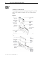
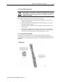
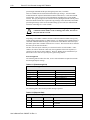
Section 1.5
Hardware
Features
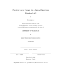
Channels are wired as differential inputs.
Module configuration is done via the controller’s programming software. The module
configuration is stored in the memory of the controller. Refer to your controller’s user
manual for more information. The illustration below shows the module’s hardware
features.
Figure 1-1
Figure 1-2
User’s Manual Pub. 0300257-01 Rev. A
Chapter 1: Module Overview
1-3
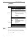
1.5.1 LED Indicators
The 1734 analog HART module uses several LEDs to show operational status. The
status LEDs are defined below:
Table 1-1 (LED Status Indicators)
Indicator
State
Module Status Off
Description
No power applied to device
Green
Device operating normally
Flashing Green
Device needs commissioning due to configuration
missing, incomplete, or incorrect
Flashing Red
Unrecoverable fault may require device replacement.
Red
Recoverable fault.
Flashing Red/Green Device is in self-test mode.
Network status Off
Device is not on-line
- Device has not completed dup_MAC_id test.
- Device not powered - check module status indicator
Flashing Green
Device is on-line but has no connections in the
established state.
Green
Device on-line and has connections in the established
state.
Flashing Red
One or more I/O connections in timed-out state
Red
Critical link failure - failed communication device.
Device detected error that prevents it communicating
on the network.
Flashing
Red/Green
Communication faulted device - the device has
detected a network access error and is in
communication faulted state.
Channel status Off
Channel not in use
Solid Green
Normal (channel scanning inputs)
Flashing Green
Channel receiving HART data
Solid Red
No power or major channel fault
Flashing Red
Channel at end of range
Flashing Red/Green Hart device error on HART enabled channel
Section 1.6
System
Overview
The module communicates to the controller via a 1734 Control Net, Device Net or
Ethernet adapter. The module receives 5 and 24V dc power through the bus interface.
Note: No external power supply is required for 2-wire input transmitters.
1.6.1 Module Power-up
At power-up, the module performs a check of its internal circuits, memory, and basic
User’s Manual Pub. 0300257-01 Rev. A
1-4
Point IO™ 2/4 Channel Analog HART Module
functions. If no faults are found during power-up diagnostics, the module status LED is
turned on.
After power-up checks are complete, the module waits for valid channel configuration
data. If an invalid configuration is detected, the module will generate a PLC fault. Once
a channel is properly configured and enabled, it continuously converts the input data to a
value within the range selected for that channel.
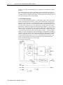
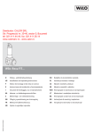
1.6.2 Module Operation
The 1734sc-IE2CH and IE4CH modules are single ended 4-20mA current sensing input
modules with HART master capability. Analog current is measured by sensing voltage
drop across an internal resistor. The nominal input resistance of individual channels is
250ohms. In the event of an over-current fault the module will protect the input circuitry
by increasing the input resistance to limit input current. Analog to digital conversion is
performed by a multiplexed Sigma-Delta ADC shared by all channels. A range of notch
filters as well as an averaging filter can be applied to analog inputs. All channels share a
common ground. Field power is provided on the terminal block to simplify wiring. The
1734sc-IE2CH and IE4CH have HART Primary Master capability. A dedicated HART
modem is used for each channel for maximum throughput. When HART functionality is
enabled on a channel the module will discover and establish communication with HART
revision 5 and greater devices. Once communication has been established the module
will automatically gather HART PV, SV, TV, FV data and monitor device status. The
modules provide a communication bridge to HART devices for Asset Management
Software and Ladder Programs via CIP messaging.
See the block diagram below.
User’s Manual Pub. 0300257-01 Rev. A
Chapter 2
Installation and Wiring
This chapter will cover:
•
Compliance to European union directives
•
Power requirements
•
General considerations
•
Mounting
•
Field wiring connections
Section 2.1
Compliance to
European
Union Directives
This product is approved for installation within the European Union and EEA regions. It
has been designed and tested to meet the following directives.
2.1.1 EMC Directive
The 1734sc-IExCH module is tested to meet Council Directive 89/336/EEC
Electromagnetic Compatibility (EMC) and the following standards, in whole or in part,
documented in a technical construction file:
•
IEC 61000-6-4 Electromagnetic compatibility (EMC) - Part 6-4: Generic
standards - Emission standard for industrial environments
•
IEC 61000-6-2 Electromagnetic compatibility (EMC) – Part 6-2: Generic
standards – Immunity for industrial environments
This product is intended for use in an industrial environment.
2.1.2 Low Voltage Directive
This product is tested to meet Council Directive 73/23/EEC Low Voltage, by applying
the safety requirements of EN 61131-2Programmable Controllers, Part 2 – Equipment
Requirements and Tests. For specific information required by EN61131-2, see the
appropriate sections in this publication, as well as the following Allen-Bradley
publications:
•
Industrial Automation, Wiring and Grounding Guidelines for Noise Immunity,
publication 1770-4.1
•
Automation Systems Catalog, publication B113
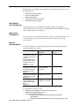
Section 2.2
Power
Requirements
The module receives power through the bus interface from the +5V dc/+24V dc system
power supply. The maximum current drawn by the module is shown in the table below.
User’s Manual Pub. 0300257-01 Rev. A
2-2
Point IO™ 2/4 Channel Analog HART Module
5 VDC
24 VDC
15 mA
20 mA
Use the table below to determine the maximum number of IExCH modules that can be
installed in a MicroLogix system.
Section 2.3
General
Considerations
1734 I/O is suitable for use in an industrial environment when installed in accordance
with these instructions. Specifically, this equipment is intended for use in clean, dry
environments Pollution degree 21 and to circuits not exceeding Over Voltage Category
II2(IEC 60664-1)3.
2.3.1 Hazardous Location Considerations
This equipment is suitable for use in Class I, Division 2, Groups A, B, C, D or nonhazardous locations only. The following WARNING statement applies to use in
hazardous locations.
!
Attention
EXPLOSION HAZARD
• Substitution of components may impair suitability for Class I,
Division 2.
• Do not replace components or disconnect equipment unless
power has been switched off or the area is known to be nonhazardous.
• Do not connect or disconnect components unless power has
been switched off or the area is known to be non-hazardous.
• This product must be installed in an IP54 rated enclosure.
• All wiring must comply with N.E.C. article 501-4(b).
1
Pollution Degree 2 is an environment where, normally, only non-conductive pollution occurs except that
occasionally a temporary conductivity caused by condensation shall be expected.
2
Over Voltage Category II is the load level section of the electrical distribution system. At this level
transient voltages are controlled and do not exceed the impulse voltage capability of the product’s
insulation.
3
Pollution Degree 2 and Over Voltage Category II are International Electrotechnical Commission (IEC)
designations.
User’s Manual Pub. 0300257-01 Rev. A
Chapter 2: Installation and Wiring
2-3
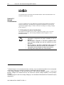
2.3.2 Prevent Electrostatic Discharge
!
Attention
Electrostatic discharge can damage integrated circuits or
semiconductors if you touch analog I/O module bus connector pins or
the terminal block on the input module. Follow these guidelines when
you handle the module:
• Touch a grounded object to discharge static potential.
• Wear an approved wrist-strap grounding device.
• Do not touch the bus connector or connector pins.
• Do not touch circuit components inside the module.
• If available, use a static-safe work station.
• When it is not in use, keep the module in its static-shield bag.
2.3.3 Remove Power
!
Attention
Remove power before removing or inserting this module. When you
remove or insert a module with power applied, an electrical arc may
occur. An electrical arc can cause personal injury or property damage
by:
• Sending an erroneous signal to your system’s field devices,
causing unintended machine motion
• Causing an explosion in a hazardous environment
Electrical arcing causes excessive wear to contacts on both the module
and its mating connector and may lead to premature failure.
2.3.4 Selecting a Location
Reducing Noise
Most applications require installation in an industrial enclosure to reduce the effects of
electrical interference. Analog inputs are highly susceptible to electrical noise. Electrical
noise coupled to the analog inputs will reduce the performance (accuracy) of the module.
Group your modules to minimize adverse effects from radiated electrical noise and heat.
Consider the following conditions when selecting a location for the analog module.
Position the module:
•
Away from sources of electrical noise such as hard-contact switches, relays, and
AC motor drives
•
Away from modules which generate significant radiated heat. Refer to the
module’s heat dissipation specification.
In addition, route shielded, twisted-pair analog input wiring away from any high voltage
I/O wiring.
Section 2.4
Mounting
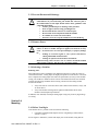
2.4.1 Before You Begin
Note that this series C product can be used with the following:
•
ControlNet and EtherNet/IP adapters ONLY, using RSLogix 5000 software,
version 11 or later
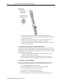
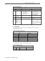
See the figures to familiarize yourself with major parts of the module, noting that the
User’s Manual Pub. 0300257-01 Rev. A
2-4
Point IO™ 2/4 Channel Analog HART Module
wiring base assembly is one of the following:
•
1734-TB or 1734-TBS POINT I/O two-piece terminal base, which includes the
1734-RTB removable terminal block and 1734-MB mounting base
•
1734-TOP or 1734-TOPS POINT I/O one-piece terminal base
User’s Manual Pub. 0300257-01 Rev. A
Chapter 2: Installation and Wiring
2-5
2.4.2 Install Mounting Base
!
Attention
During panel or DIN rail mounting of all devices, be sure that all debris
(metal chips, wire strands, etc.) is kept from falling into the module.
Debris that falls into the module could cause damage when power is
applied to the module.
To install the mounting base on the DIN rail, proceed as follows:
1.) Position the mounting base vertically above the installed units (adapter, power
supply or existing module.
2.) Slide the mounting base down allowing the interlocking side pieces to engage
the adjacent module or adapter.
3.) Press firmly to seat the mounting base on the DIN rail. The mounting base will
snap into place.
4.) To remove the mounting base from the DIN rail, remove the module, and use a
small bladed screwdriver to rotate the base locking screw to a vertical position.
This releases the locking mechanism. Then lift straight up to remove.
2.4.3 Install the I/O Module
The module can be installed before, or after base installation. Make sure that the
mounting base is correctly keyed before installing the module into the mounting base. In
addition, make sure the mounting base locking screw is positioned horizontal referenced
to the base.
User’s Manual Pub. 0300257-01 Rev. A
2-6
Point IO™ 2/4 Channel Analog HART Module
1.) Using a bladed screwdriver, rotate the key switch on the mounting base
clockwise until the number required for the type of module being installed aligns
with the notch in the base.
2.) Make certain the DIN rail locking screw is in the horizontal position. (You
cannot insert the module if the locking mechanism is unlocked.)
3.) Insert the module straight down into the mounting base and press to secure. The
module will lock into place.
2.4.4 Install the Removable Terminal Block (RTB)
A removable terminal block is supplied with your wiring base assembly. To remove the
terminal block, pull up on the RTB handle. This allows the mounting base to be removed
and replaced as necessary without removing any of the wiring. To reinsert the removable
terminal block, proceed as follows.
1.) Insert the end opposite the handle into the base unit. This end has a curved
section that engages with the wiring base.
2.) Rotate the terminal block into the wiring base until it locks itself in place.
3.) If an I/O module is installed, snap the RTB handle into place on the module.
2.4.5 Remove a Mounting Base
To remove a mounting base, you must remove any installed module, and the module
installed in the base to the right. Remove the removable terminal block (if wired).
1.) Unlatch the RTB handle on the I/O module.
2.) Pull on the RTB handle to remove the removable terminal block.
3.) Press on the module lock on the top of the module.
4.) Pull on the I/O module to remove from the base.
5.) Repeat steps 1, 2, 3 and 4 for the module to the right.
6.) Use a small bladed screwdriver to rotate the orange base locking screw to a
User’s Manual Pub. 0300257-01 Rev. A
Chapter 2: Installation and Wiring
2-7
vertical position.
This releases the locking mechanism.
7.) Lift straight up to remove.
2.4.6 Install a 1734-TOPS Base
1.) Position the base vertically above the installed units, such as an adapter, power
supply, or existing module.
2.) Slide the base down, allowing the interlocking side pieces to engage the adjacent
installed unit.
3.) Press firmly to seat the base on the DIN rail until the base snaps into place.
4.) Verify that the DIN-rail locking screw is in a horizontal, locked position before
inserting an I/O module.
2.4.7 Remove a 1734-TOPS Base
To remove a wiring base from the DIN rail, you must remove the module installed to the
right of the base.
1.) Squeeze the module locking mechanism of the module to the right of the base,
pulling up to remove the module.
2.) Turn the orange locking screw to a vertical position to unlock the base from the
DIN rail.
3.) Slide the base up to release it from its mating units.
Section 2.5
Field Wiring
Connections
Consider the following when wiring your system:
General
•
Power and input wiring must be in accordance with Class 1, Division 2 wiring
methods, Article 501-4(b) of the National Electric Code, NFPA 70, and in
accordance with the authority having jurisdiction.
•
Use Belden™ 8761, or equivalent, shielded wire.
•
To ensure optimum accuracy, limit overall cable impedance by keeping a cable
as short as possible. Locate the module as close to input devices as the
application permits.
•
Digital and analog power must be supplied by an Isolated Secondary Limited
Energy Low Voltage source.
Inputs
•
The module provides loop power for analog inputs.
User’s Manual Pub. 0300257-01 Rev. A
2-8
Point IO™ 2/4 Channel Analog HART Module
Grounding
USE SUPPLY WIRES SUITALE FOR 10°C ABOVE SURROUNDING
AMBIENT
!
Attention
!
Attention
UTILISER DES FILS D’ALIMENTATION QUI CONVIENNENT A
UNE TEMPERATURE DE 10°C AU-DESSUS DE LA
TEMPERATURE AMBIANTE
•
This product is intended to be mounted to a well-grounded mounting surface
such as a metal panel. Additional grounding connections from the module’s
mounting tabs or DIN rail (if used) are not required unless the mounting surface
cannot be grounded.
•
Under normal conditions, the drain wire (shield) should be connected to the
metal mounting panel (earth ground). Keep shield connection to earth ground as
short as possible.
•
Ground the shield drain wire at one end only. The typical location is as follows:
•
o
For grounded thermocouples or millivolt sensors, this is at the sensor
end.
o
For insulated/ungrounded thermocouples, this is at the module end.
Contact your sensor manufacturer for additional details.
Refer to Industrial Automation Wiring and Grounding Guidelines, AllenBradley publication 1770-4.1, for additional information.
Noise Prevention
•
Route field wiring away from any other wiring and as far as possible from
sources of electrical noise, such as motors, transformers, contactors, and ac
devices. As a general rule, allow at least 15.2 cm (6 in.) of separation for every
120V of power.
•
Routing field wiring in a grounded conduit can reduce electrical noise.
•
If field wiring must cross ac or power cables, ensure that they cross at right
angles.
•
If noise persists for a device, try grounding the opposite end of the cable shield
or ground both ends of the shield.
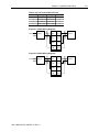
2.5.1 Wiring Diagram
Refer to the following wiring diagrams for field wiring connections.
Table 2-1 (4 Ch Terminal Block Pinout)
RTB Pin#
Usage
Usage
RTB Pin#
0
Input 0
Input 1
1
2
Input 2
Input 3
3
4
Common Field Power
5
6
Chas GND Chas GND
7
User’s Manual Pub. 0300257-01 Rev. A
Chapter 2: Installation and Wiring
Table 2-2 (2 Ch Terminal Block Pinout)
RTB Pin#
Usage
Usage
RTB Pin#
0
Input 0
Input 1
1
2
Field Power Field Power
3
4
Common
Common
5
6
Chas GND Chas GND
7
Figure 2-1 (IE4CH Wiring Diagram)
AC/DC Pwr
4 Wire
Device
0
IN 0
1
IN 1
2
IN 2
3
IN 3
4
COM
5
+ 24
6
FGN
7
FGN
2 Wire
Device
Figure 2-2 (IE2CH Wiring Diagram)
AC/DC Pwr
4 Wire
Device
User’s Manual Pub. 0300257-01 Rev. A
0
IN 0
1
IN 1
2
+ 24
3
+ 24
4
COM
5
COM
6
FGN
7
FGN
2 Wire
Device
2-9
2-10
Point IO™ 2/4 Channel Analog HART Module
User’s Manual Pub. 0300257-01 Rev. A
Chapter 3
Configuring the 1734sc-IExCH
Using RSLogix 5000
This chapter covers the following subjects:
•
Introduction
•
About Communications
•
Use Generic Profile
•
Use AOP (Add On Profile)
•
Module configuration
•
Reading input data
•
Module update time
Section 3.1
Introduction
The 1734sc-IE2CH and IE4CH allow, in addition to reading the 4 to 20 mA analog
signal, the ability to read and write HART data to and from HART compatible devices.
This chapter will describe how to configure the IExCH module using RSLogix 5000
programming software.
Section 3.2
About
Communications
The module produces and consumes data as follows:
IE2CH Produce/Consume Data
Input Assembly Options
I/O Connection Type
Consumes
Produces
Analog + HART 0, 1
Change-of-State
0 Bytes
60 Bytes
IE4CH Produce/Consume Data
Input Assembly Options
I/O Connection Type
Consumes
Produces
Analog + HART 0, 1, 2, 3
Change-of-State
0 Bytes
112 Bytes
!
The IExCH module is not compatible with the 1734-ADN, ADN(X), and
PDN device net adapters and the 1734-APB profibus adapter.
Attention
!
Attention
It is not recommended to update module firmware if the module is
installed behind a Control Net adapter (1734-ACNR). Only update
firmware when the module is installed behind an Ethernet adapter
(1734-AENT or 1734-AENTR).
User’s Manual Pub. 0300257-01 Rev. A
3-2
Point IO™ 2/4 Channel Analog HART Module
!
Attention
The ControlNet adapter (1734-ACNR) has a maximum data transmit
limit of 600 bytes. Therefore, the maximum number of 1734sc-IE4CH
modules that can be installed behind a ControlNet adapter is four and
the maximum number of 1734sc-IE2CH modules is eight.
Section 3.3
Use Generic
Profile
The generic point IO module profile can be used to represent the IExCH module within
RSLogix 5000. The generic profile should be used for RSLogix 5000 versions 14 and
older. Before the generic profile can be added to the IO configuration, the proper
communication module needs to be added to the IO configuration first. Follow the
procedure below to add a communication module to RSLogix 5000.
1.) Add the new local communication module to your project.
2.) Configure the local module, including:
a.
Naming the module
b.
Choosing a Communication Format
c.
Setting the Revision level
d.
Setting the module location as necessary such as the slot number for a
1756-CNB module
e.
Choosing an Electronic Keying method
3.) Add the new remote module to your project, such as a 1734 Control Net adapter
or Ethernet Adapter (i.e. 1734-ACNR or 1734-AENT, respectively).
4.) Configure the remote module similarly to the local module
5.) Download the configuration to the controller
Note: If you are using Control Net, you must schedule the network using
“RSNetworks for Control Net” after adding the local and remote
communication modules.
Note: When you create a new RSLogix 5000 project with the CompactLogix
1769-L32C or L35CR controller, The Controller Organizer creates a Control
Net port in the local chassis. In this case, you don’t need to add a separate
local communication module.
Note: When you create a new RSLogix 5000 project with the CompactLogix
1769-L23E, 1769-L32E or L35E controller, The Controller Organizer creates
a Ethernet port in the local chassis. In this case, you don’t need to add a
separate local communication module.
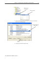
3.3.1 Add a Local Ethernet Bridge Module
After you have started RSLogix 5000 software and created a controller project, you can
add Ethernet communication modules. A local Ethernet communication module is a
module that resides in the same chassis as the controller.
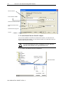
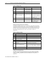
1.) Select a New Module for the I/O Configuration.
User’s Manual Pub. 0300257-01 Rev. A
Chapter 3: Configuring the 1734sc-IExCH for RSLogix 5000
3-3
Right-click on I/O
Configuration
Select New Module
2.) Select the module type from the Select Module Type pop-up. The example
below uses a 1756-ENBT module.
Select the local Ethernet
bridge module
Click OK
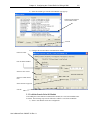
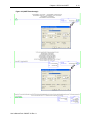
3.) Configure the local Ethernet bridge module.
User’s Manual Pub. 0300257-01 Rev. A
3-4
Point IO™ 2/4 Channel Analog HART Module
Name the module
Enter IP address of ENBT
Select the module’s slot number
Select the module’s revision
level
Select electronic keying level
Click OK
3.3.2 Add a Remote Ethernet Point IO Adapter
After you have added the local Ethernet communication module, you must add remote
Ethernet communication modules. A remote Ethernet module is a module that resides in a
separate chassis from the controller.
!
Attention
If you plan to use the 1734 Control Net adapter, you will need to install
the 1734sc-IExCH EDS file before scheduling the network. The latest
EDS files can be found at (www.spectrumcontrols.com).
1.) Select a New Module for the I/O Configuration.
Right-click on the local
communication module
Select New Module
User’s Manual Pub. 0300257-01 Rev. A
Chapter 3: Configuring the 1734sc-IExCH for RSLogix 5000
3-5
2.) Select the module type from the Select Module Type pop-up.
Select the remote Ethernet
communication module.
Click OK
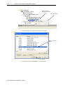
3.) Configure the remote Ethernet communication module.
Name the module
Enter IP address of ENBT
Select the comm. format
Select the chassis size
Select the module revision
level
Select electronic keying level
Click OK
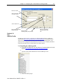
3.3.3 Add the Generic Point IO Module
After adding the remote Ethernet communication module, the 1734 Generic Module must
be added. The following steps must be followed to add the 1734 Generic IO Module.
1.) Select a New Module for the I/O Configuration.
User’s Manual Pub. 0300257-01 Rev. A
3-6
Point IO™ 2/4 Channel Analog HART Module
Right-click on the
remote communication
Select New Module
2.) Select the module type from the Select Module Type pop-up.
Select Generic Flex
Module
Click OK
3.) Configure the Generic 1734 Module (i.e. 1734sc-IExCH)
User’s Manual Pub. 0300257-01 Rev. A
Chapter 3: Configuring the 1734sc-IExCH for RSLogix 5000
3-7
Name the module
Enter “Input Data – SINT”
for Comm. Format
Enter module slot #
Enter the input assembly
instance and size.
Enter the output
assembly (always 190) Click OK
Enter the configuration
assembly instance and
size.
Section 3.4
Use
Add-On-Profile
For RSLogix 5000 version 15 and greater an Add-On module profile is available for
download at (http://www.spectrumcontrols.com/downloads.htm). The Add-On profile
allows the user to add the IExCH module to the RSLogix 5000 module pick list. The
profile provides configuration and information screens to the user to simplify installation.
Follow the procedure below to install and use the Add-On profile.
3.4.1 Installing the Add-On profile
1.) Download the zipped file from the Spectrum Controls website and unzip
the file (http://www.spectrumcontrols.com/downloads.htm)
2.)
Open the created folder and double-click on the MPSetup.exe file.
3.) Follow the online prompts.
User’s Manual Pub. 0300257-01 Rev. A
3-8
Point IO™ 2/4 Channel Analog HART Module
3.4.2 Adding the IExCH Module To Your Logix Project
Once the profiles are installed you can access them through RSLogix 5000 via the I/O
Configuration. Follow the procedure below to add a module:
1.) Before you can add the 1734sc-IExCH to your RSLogix 5000 project, you must
first add a local communication module and a remote communication adapter.
Complete sections 3.3.1 and 3.3.2 above, before proceeding to step 2 below.
2.) In the I/O Configuration, right mouse click on the Point IO backplane under the
remote communication adapter that you added in step one above and select
“New Module”.
3.) When the dialog screen opens, select the “By Vender” tab and expand the
Spectrum Controls folder.
4.) Highlight the module and press the “OK” button.
5.) Give the module a unique name.
User’s Manual Pub. 0300257-01 Rev. A
Chapter 3: Configuring the 1734sc-IExCH for RSLogix 5000
3-9
Name the module
6.) Enter an RPI Rate
Set the RPI rate
7.) Configure the rest of the module using the “Module Configuration” tab and the
“Channel Configuration” tab.
Section 3.5
Module
Configuration
The IExCH can be configured using the AOP (Add-On-Profile) or by using the 1734
generic module profile. The configuration tags for the IExCH are located under the
controller tags. The following examples describe the tag structure allocated by the
Generic Module profile and the AOP.
User’s Manual Pub. 0300257-01 Rev. A
3-10
Point IO™ 2/4 Channel Analog HART Module
Generic Module Profile:
[Name of remote communication module]:e:x.Data[0 to 198]
e = IExCH slot number
x = Image Type (i.e. C, I, or O)
AOP (Add-On-Profile):
[Name of remote communication module]:e:x
e = IE4CH slot number
x = Image Type (i.e. C, I, or O)
Note: The AOP will provide a predefined tag structure for the
configuration. See example below.
Figure 3-1 (AOP Config. Tags)
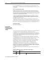
Table 3-1 (IE2CH Configuration Assembly)
Instance: 225
Size: 50 Bytes (DNET 46 Bytes)
OFFSET
FIELD
TYPE
BYTES
0x00 – 0x11
Channel 1 Configuration
STRUCT
20
+0x00
Low Engineering Channel 0
INT
2
+0x02
High Engineering Channel 0
INT
2
+0x04
Digital Filter Channel 0
INT
2
+0x06
Low Alarm Channel 0
INT
2
+0x08
High Alarm Channel 0
INT
2
+0x0A
Low Low Alarm Channel 0
INT
2
+0x0C
High High Alarm Channel 0
INT
2
+0x0E
Reserved pad alignment bytes
SINT
1
+0x0F
Alarm Latch Channel 0
SINT
1
+0x10
Enable Hart Channel 0
SINT
1
+0x11
Alarm Disable Channel 0
SINT
1
+0x12
Reserved pad alignment bytes
INT
2
0x14
Channel 1 Configuration
User’s Manual Pub. 0300257-01 Rev. A
STRUCT
20
Chapter 3: Configuring the 1734sc-IExCH for RSLogix 5000
Instance: 225
Size: 50 Bytes (DNET 46 Bytes)
OFFSET
FIELD
3-11
TYPE
BYTES
(same structure as Ch.0 above)
0x28
Notch Filter (All Channels)
SINT
1
0x29
pad
SINT
1
0x2A
RTS (All Channels)
INT
2
0x2C
Hart Pass-Through Hold Time
UINT
2
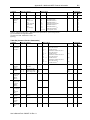
Table 3-2 (IE4CH Configuration Assembly)
Instance: 225
Size: 90 Bytes (DNET 86 Bytes)
OFFSET
FIELD
TYPE
BYTES
0x00 – 0x11
Channel 1 Configuration
STRUCT
20
+0x00
Low Engineering Channel 0
INT
2
+0x02
High Engineering Channel 0
INT
2
+0x04
Digital Filter Channel 0
INT
2
+0x06
Low Alarm Channel 0
INT
2
+0x08
High Alarm Channel 0
INT
2
+0x0A
Low Low Alarm Channel 0
INT
2
+0x0C
High High Alarm Channel 0
INT
2
+0x0E
Reserved pad alignment bytes
SINT
1
+0x0F
Alarm Latch Channel 0
SINT
1
+0x10
Enable Hart Channel 0
SINT
1
+0x11
Alarm Disable Channel 0
SINT
1
+0x12
Reserved pad alignment bytes
INT
2
0x14
Channel 1 Configuration
(same structure as Ch.0 above)
STRUCT
20
0x28
Channel 2 Configuration
(same structure as Ch.0 above)
STRUCT
20
0x3C
Channel 3 Configuration
(same structure as Ch.0 above)
STRUCT
20
0x50
Notch Filter (All Channels)
SINT
1
0x51
pad
SINT
1
0x52
RTS (All Channels)
INT
2
0x54
Hart Pass-Through Hold Time
UINT
2
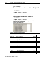
3.5.1 Channel Configuration
Low Engineering
The minimum scaled value that will be displayed when the analog input signal is at 4
mA. This feature is applied on a per channel basis.
User’s Manual Pub. 0300257-01 Rev. A
3-12
Point IO™ 2/4 Channel Analog HART Module
High Engineering
The maximum scaled value that will be displayed when the analog input signal is at 20
mA. This feature is applied on a per channel basis.
Digital Filter
The digital filter smoothes input data noise transients. This feature is applied on a per
channel basis. The digital filter value specifies the time constant for a digital first order
lag filter on the input data. A value of 0 disables the filter.
The digital filter equation is a classic first order lag equation.
Yn = Filtered Input Value
Yprevn = Previous Filtered Input Value
Tdelta = Change in time(msec)
TA = User supplied Time Constant(msec)
Xn = new unfiltered input value
Yn = Yprevn + ( (Tdelta/ (Tdelta + TA)) * (Xn – Yprevn) )
Value Units: Milliseconds
Value Limits: 0-20100, if not 0(feature disabled) then value must be greater than 2 * RTS
Value else Configuration Error
Low Alarm
A low alarm will activate if the value of the scaled input is at or below this value. It will
clear (if not latched) when the scaled input rises above this value.
High Alarm
A high alarm will activate if the value of the scaled input is at or above this value. It will
clear (if not latched) when the scaled input drops below this value.
Low-Low Alarm
A low-low alarm will activate if the value of the scaled input is at or below this value. It
will clear (if not latched) when the scaled input rises above this value.
High-High Alarm
A high-high alarm will activate if the value of the scaled input is at or above this value. It
will clear (if not latched) when the scaled input drops below this value.
Reserved (set to zero)
Alarm Latch
0: Process alarms are not latched for associated channel.
1: Process alarms are latched for associated channel.
User’s Manual Pub. 0300257-01 Rev. A
Chapter 3: Configuring the 1734sc-IExCH for RSLogix 5000
3-13
Alarm Disable
0: Process alarms enabled for associated channel.
1: Process alarms disabled for associated channel.
Enable HART Communication
0: Disable HART communication on associated channel.
1: Enable HART communication on associated channel.
3.5.2 Analog Notch Filter
The analog notch filter selection affects how the module attenuates the input signal at the
specified frequency. It also affects the update time of the input data which is reflected in
the minimum real time sample (RTS) rate that is available.
Table 3-3 (Analog Filter)
Notch Filter Selection 50/60Hz 50Hz 60Hz 100Hz 120Hz 240Hz 480Hz
Tag Value
1
2
3
4
5
6
7
Filter Setting
96
96
80
48
40
20
10
Settling Time
(ms)
60
60
50
30
25
12.5
6.25
4 Channel
Sample Time
(RTS msec)
248
248
208
128
108
58
33
2 Channel
Sample Time
(RTS msec)
128
128
108
68
58
33
21
One setting applies to all channels in the module.
Value Units: NA
Value Limits: 1-7 (see Table 3-3 above)
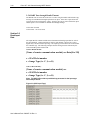
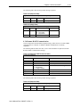
3.5.3 RTS (Real Time Sample)
This parameter instructs the module how often to scan its input channels and obtain new
sampled data. After the channels are scanned, the module broadcasts that data over the
backplane.
Value Units: Milliseconds
Value Limits: 21-10,000 for IE2CH or 33 – 10,000 for IE4CH, actual minimum allowed
is based upon Module Filter selection Each module Filter selection will limit the
minimum value allowed, see Table 3-3.
User’s Manual Pub. 0300257-01 Rev. A
3-14
Point IO™ 2/4 Channel Analog HART Module
3.5.4 HART Pass-through Handle Timeout
The Handle time out value allows the user to set how long the module will hold the reply
message for a HART Pass-through operation in its queue. If the time expires before the
reply has been retrieved using the “Query” message, the reply is removed from the queue
and the queue is now available for another Pass-through message.
Value Units: Seconds
Value Limits: 1 to 255 seconds.
Section 3.6
Read Input
Data
The input data file contains module status information and analog input data for each of
the input channels. Analog input data is read for each channel, converted to a scaled
digital value, and stored in the input tags. The input tags for the IExCH are located under
the controller tags. The following examples describe the tag structure allocated by the
Generic Module profile and the AOP.
Generic Module Profile:
[Name of remote communication module]:e:x.Data[0 to 198]
e = IExCH slot number
x = Image Type (i.e. C, I, or O)
AOP (Add-On-Profile):
[Name of remote communication module]:e:x
e = IE4CH slot number
x = Image Type (i.e. C, I, or O)
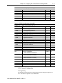
Note: The AOP will provide a predefined tag structure for the input tags.
See example below.
Figure 3-2 (AOP Input Tags)
User’s Manual Pub. 0300257-01 Rev. A
Chapter 3: Configuring the 1734sc-IExCH for RSLogix 5000
3-15
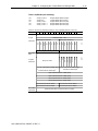
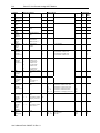
Table 3-4 (IE2CH Input Assembly)
Instance:
104
100
101
102
103
Description:
Analog + Hart 0,1
Analog Only
Analog + Hart 0
Analog + Hart 0, 1
Analog + Hart 0, 1
Total Size:
60 Bytes RSL5K (DNet 56 bytes)
12 Bytes RSL5K (Dnet 8 bytes)
36 Bytes RSL5K (Dnet 32 bytes)
60 Bytes RSL5K (Dnet 56 bytes)
60 Bytes RSL5K (Dnet 56 bytes)
( instance 104 is the default, instances 100-101 are subsets available to conserve bandwidth,
instances 102,103 are redundant included for code compatibility between 2 and 4 ch )
Bit
15
14
13
12 11 10 09 08 07 06 05 04 03 02 01
Analog data
Channel 0 Data - INT
Channel 1 Data - INT
8 bytes
0x00-0x07
00
Status Byte for Channel 1
Status Byte for Channel 0
CF
CM
LA
HA
LLA
HHA
UR
OR
CF
CM
LA
HA
LLA
HHA
UR
OR
Reserved alignment pad byte - SINT Reserved alignment pad byte - SINT
Ch. 0 Hart
Data
Input Ch 0 Hart Device Status Byte Input Ch0 Hart Device Status Byte 0
1
Input Ch 0 Hart Device Status Byte Input Ch 0 Hart Device Status Byte 2
3
Field Device Status Byte2
Extended Device Status Byte3
Input Channel 0 Hart PV - REAL (float)
Input Channel 0 Hart SV - REAL (float)
Input Channel 0 Hart TV - REAL (float)
Input Channel 0 Hart FV - REAL (float)
Input Channel 0 Hart SV Status
Input Channel 0 Hart PV Status
Input Channel 0 Hart FV Status
Input Channel 0 Hart TV Status
Ch .1 Hart
0x20-0x38
User’s Manual Pub. 0300257-01 Rev. A
(Data structure same as channel 0 above, 24 bytes)
INIT
FAIL
MAFLT
MSGRDY
DDLDR
DDLGX
SUA
Response Code1
0x08-0x1F
FAULT
24 bytes
3-16
Point IO™ 2/4 Channel Analog HART Module
ANALOG STATUS BITS:
CF = Channel Fault status; 0 = no error, 1 = fault
CM = Calibration Mode; 0 = normal, 1 = calibration mode
LA = Low Alarm; 0 = no error, 1 = fault
HA = High Alarm; 0 = no error, 1 = fault
LLA = Low/Low Alarm; 0 = no error, 1 = fault
HHA = High/High Alarm; 0 = no error, 1 = fault
UR = Underrange; 0 = no error, 1 = fault
OR = Overrange; 0 = no error, 1 = fault
HART STATUS BITS:
INIT = HART device detected
FAIL = No device found or communication failed
MAFLT = HART does not match analog loop current
MSGRDY = Ladder pass-through message available
DDLDR = Device Data update Ladder
(New HART Device Information Available see page 4-6)
DDLGX = Device Data update Logix (Reserved – Not Used)
SUA = Status Update Available, Cmd48 data changed
FAULT= HART device reports a fault
1
2
3
See page # B-2 for more information.
See page # B-2 for more information.
This is the first byte returned by HART command 9 when HART version 6 or 7 is used.
0x04 = Critical Power Failure, 0x02 = Device Variable Alert, 0x01 = Maintenance Required
User’s Manual Pub. 0300257-01 Rev. A
Chapter 3: Configuring the 1734sc-IExCH for RSLogix 5000
3-17
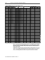
Table 3-5 (IE4CH Input Assembly)
Instance:
104
100
101
102
103
Description:
Analog + Hart 0,1,2,3
Analog Only
Analog + Hart 0
Analog + Hart 0,1
Analog + Hart 0,1,2
Total Size:
112 Bytes RSL5K (DNet 108 bytes)
16 Bytes RSL5K (Dnet 12 bytes)
40 Bytes RSL5K (Dnet 36 bytes)
64 Bytes RSL5K (DNet 60 bytes)
88 Bytes RSL5K (DNet 84 bytes)
( instance 104 is the default, instances 100-103 are subsets available to conserve bandwidth )
12
11
10
09
08
07
06
05
Analog data
Channel 0 Data - INT
12 bytes
Channel 1 Data - INT
04
03
02
01
00
CF
13
CF
14
CM
15
CM
Bit
Channel 2 Data - INT
0x00-0x0B
Channel 3 Data - INT
Status Byte for Channel 1
Status Byte for Channel 0
LA
HA
LLA
HHA
UR
OR
CF
CM
LA
HA
LLA
HHA
UR
OR
Status Byte for Channel 3
Status Byte for Channel 2
LA
HA
LLA
HHA
UR
OR
CF
CM
LA
HA
LLA
HHA
UR
OR
Ch. 0 Hart Data Input Ch 0 Hart Device Status Byte 1 Input Ch 0 Hart Device Status Byte 0
INIT
FAIL
MAFLT
MSGRDY
DDLDR
DDLGX
SUA
Response Code1
0x0C-0x23
FAULT
24 bytes
Input Ch 0 Hart Device Status Byte 3 Input Ch 0 Hart Device Status Byte 2
Extended Device Status Byte3
Field Device Status Byte2
Input Channel 0 Hart PV - REAL (float)
Input Channel 0 Hart SV - REAL (float)
Input Channel 0 Hart TV - REAL (float)
Input Channel 0 Hart FV - REAL (float)
Input Channel 0 Hart SV Status
Input Channel 0 Hart PV Status
Input Channel 0 Hart FV Status
Input Channel 0 Hart TV Status
Ch .1 Hart
0x24-0x3B
(Data structure same as channel 0 above, 24 bytes)
Ch.2 Hart
0x3C-0x53
(Data structure same as channel 0 above, 24 bytes)
Ch.3 Hart
0x54-0x6B
(Data structure same as channel 0 above, 24 bytes)
User’s Manual Pub. 0300257-01 Rev. A
3-18
Point IO™ 2/4 Channel Analog HART Module
ANALOG STATUS BITS:
CF = Channel Fault status; 0 = no error, 1 = fault
CM = Calibration Mode; 0 = normal, 1 = calibration mode
LA = Low Alarm; 0 = no error, 1 = fault
HA = High Alarm; 0 = no error, 1 = fault
LLA = Low/Low Alarm; 0 = no error, 1 = fault
HHA = High/High Alarm; 0 = no error, 1 = fault
UR = Underrange; 0 = no error, 1 = fault
OR = Overrange; 0 = no error, 1 = fault
HART STATUS BITS:
INIT = HART device detected
FAIL = No device found or communication failed
MAFLT = HART does not match analog loop current
MSGRDY = Ladder pass-through message available
DDLDR = Device Data update Ladder
(New HART Device Information Available see page 4-6)
DDLGX = Device Data update Logix (Reserved – Not Used)
SUA = Status Update Available, Cmd48 data changed
FAULT= HART device reports a fault
1
2
3
See page # B-2 for more information.
See page # B-2 for more information.
This is the first byte returned by HART command 9 when HART version 6 or 7 is used.
0x04 = Critical Power Failure, 0x02 = Device Variable Alert, 0x01 = Maintenance Required
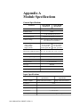
Section 3.7
Module
Update Time
The module update time is determined by the number of input channels enabled and by
the filter frequency selected for each channel.
Table 3-6 (Module Update Time)
Filter Frequency
1734sc-IE2CH
1734sc-IE4CH
50/60 Hz (Default)
488 ms
248 ms
50 Hz
248 ms
128 ms
60 Hz
208 ms
108 ms
100 Hz
128 ms
68 ms
120 Hz
108 ms
58 ms
240 Hz
58 ms
33 ms
480 Hz
33 ms
21 ms
User’s Manual Pub. 0300257-01 Rev. A
Chapter 4
IExCH and HART
This chapter describes how to read and write HART data using the IExCH module. This
chapter includes the following sections:
•
HART features
•
Detecting HART devices
•
Auto scanning of HART dynamic variables
•
Supported HART CIP messages
Section 4.1
HART Features
The IExCH module will function as a HART master and will communicate with HART
devices running HART revision 5 or greater. Ther IExCH module includes one HART
modem per channel to provide maximum acquisition speed and flexibility. The block
diagram in section 1.6.2 describes the internal architecture of the module including the
placement of the HART modems. The module performs the following HART operations:
•
Automatically reads the four dynamic HART variables PV,SV,TV, and FV
•
Automatically retrieves and stores HART device information including,
manufacturer’s ID, device tag name, HART revision level, etc., and makes the
information available via a CIP unconnected message
•
The module automatically retrieves and stores extended device status, using
HART command 48. The extended status can be retrieved using an
unconnected CIP message.
•
A HART pass-through interface using CIP unconnected messaging provides the
ability for the user, or remote client, to send a HART command to a HART
enabled device.
Section 4.2
Detecting HART
Devices
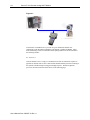
HART communication can be enabled independently on each channel. For more
information on configuring HART on a specific channel, refer to Chapter 3. When a
channel is enabled for HART, the IExCH module will act as a primary HART master and
the HART enabled field device will act as a HART slave. Any given channel may have a
master (i.e. the IExCH), a secondary master (hand held configuration tool), and a slave
device connected simultaneously. Please see figure below.
User’s Manual Pub. 0300257-01 Rev. A
4-2
Point IO™ 2/4 Channel Analog HART Module
Figure 4-1
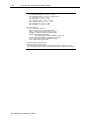
To determine if a HART device is present on a given channel the module will
continuously send out HART command 0 if the channel is enabled for HART. Short
frame addressing is used on command 0 and the polling address will be incremented in
the following manner:
0,1-15,16-63, 0
Once the module receives a reply to command 0 it will start its connection sequence to
populate its internal cache of device data for that channel and then proceed to scanning of
the dynamic variables and processing pass-through requests. The data acquisition
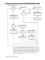
process is described in the flow chart shown on the following page.
User’s Manual Pub. 0300257-01 Rev. A
Chapter 4: IExCH and HART
4-3
Figure 4-2 (Connect Cycle)
Device
in scan
list?
No
Send Command 0
Read Unique Identifier
Read
configuration
information, such as
tag, units, range, etc.
Yes
Reply?
Send Command 3 or 9
to read Dynamic
process variable
Yes
Signal
configuration
changed in input tag
No
Put device in scan list
Reply?
Yes
Update Input Tag
No
Remove device from
scan list
New
Config.
Indicated
Yes
Read
configuration
information, such as
tag, units, range, etc.
No
Process 1
pass-through message
Signal
configuration
changed in input tag
4.2.1 Auto-Scanning of Dynamic HART Variables (PV, SV, TV, FV)
The module will continuously send Cmd 3 or Cmd 9 to the HART device connected on a
channel. Which command is sent is determined by the HART Universal revision number
of the HART device. If the device has a revision of 6 or greater then Cmd 9 is used,
otherwise for HART revision 5 devices Cmd 3 is used. The advantage of Cmd 9 is that it
contains a “Health Status” byte for each of the 4 dynamic variables that it returns. The
Dynamic variables and the status bytes are published in the module input tags. See
Section 3.6 for more information.
User’s Manual Pub. 0300257-01 Rev. A
4-4
Point IO™ 2/4 Channel Analog HART Module
Section 4.3
Supported HART
CIP Messages
CIP messages can be sent to the module using the MSG instruction to retrieve additional
HART information that is not included in the module’s input tags. This data may
include, additional HART device information, HART device extended status, HART
pass-through messaging, or the ability to temporarily suspend/resume HART
communication on any given channel. The available HART CIP messages include:
Topic
Page
Read Additional Device Status
4-4
Get HART device information
4-6
HART pass-through messaging
4-9
Flush Queue
4-14
Suspend HART communication
4-14
Resume HART communication
4-15
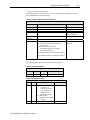
4.3.1 Read Additional Device Status
Most devices support HART command 48 which allows the HART primary or secondary
master to read additional device status information. HART command 48 is optional for
devices running HART revision 5 & 6, but is required for devices running revision 7.
Command 48 returns up to 25 bytes of status information. This group of 25 bytes
includes both pre-defined status bytes and device specific status.
The IExCH will keep an internal cache of each channels Command 48 status data and
make the data available via a CIP unconnected message. The IExCH keeps the data up to
date by monitoring the MSA (More Status Available) bit (i.e. bit 4 in the Field Device
Status Byte). See Error! Reference source not found. and Error! Reference source
not found. for more information. When the MSA changes state (i.e. changes from 0 to 1
or 1 to 0), the module will resend command 48 on the associated channel. If the MSA bit
remains set, the module will resend command 48 to the device every 2 minutes.
The SUA (Status Update Available) bit is used to notify the user that additional status for
the channel has been refreshed by the module and the user should re-send the “Read
Additional Device Status” CIP message to retrieve the cached data. After the CIP
message is sent, the bit will clear.
Note: The data returned by the “Read Additional Device Status” message
is in the original order as received from the HART device which means any
multi-byte elements in the data will be reversed in the PLC. Hart format is
MSB first and the PLC is LSB first for multi-byte variables. Since the
location of the multi-byte elements can vary depending on the device, the
module will not be able to reorder the bytes. Refer to the HART device’s
documentation for the location of each multi-byte element and reverse the
order of the bytes in ladder to interpret.
The module will update its internal data cache for command 48 under the following
conditions:
1. Initial device connection.
2. Detection of “more status available” bit change (0 to 1 or 1to 0).
User’s Manual Pub. 0300257-01 Rev. A
Chapter 4: IExCH and HART
4-5
3. Every 2 minutes if bit remains set.
The following table describes the class, service code and instances required to send the
Read Additional Device Status message.
Table 4-1 (Read Additional Device Status)
Unconnected Message
Field
Value
Definition
Message Type
Service Code
Class Name
Instance
“CIP Generic”
0x4C
0x035D
0
1-4
None, leave this field blank
Read Additional Status
HART Object
Selects All Channels
Selects channel 0-3
Object
Attribute
Request Size
Reply Size
0
2-112 bytes
(2) Size when information not available
(Instance 1-4)
(28) Up to this Size when valid
Information returned for a single
channel (Instance 1-4)
(56 if IE2CH) Fixed size returned for Instance
0
(112 if IE4CH) Fixed size returned for Instance
0
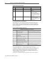
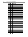
The following tables describe the possible message responses.
Table 4-2 (Request Data)
HART Read Extended Status - Request packet structure
Offset
Field
Value
Definition
No Request Data
Table 4-3 (Request Failed)
HART Read Additional Status - Reply packet structure
Offset
Field
Value
Definition
0
Status
Command status
1
Pad
34 = DR_RUNNING
(No Device or
connection process
not completed or regathering device
info is in progress)
35 = DR_DEAD
(Channel is not HART
enabled)
0
User’s Manual Pub. 0300257-01 Rev. A
Pad byte
No Request Data
Number of Data bytes
returned
4-6
Point IO™ 2/4 Channel Analog HART Module
Table 4-4 (Request Succeeded)
HART Read Extended Status - Reply packet structure
Offset
Field
Value
Definition
0
1
Status
Count
00 = SUCCESS (1 byte)
0-25(1 byte)
2-26
Additional Status Bytes
27
Pad
Command status
Number of Status bytes
available
Additional Status bytes
returned by CMD48
For Class Instance(Instance=0)
if device doesn’t return any or
all 25 bytes then the remaining
are set to 0.
Included if all 25 Additional
Status bytes returned or
returning all Channels at once
for Instance 0
0
4.3.2 Get HART Device Information
When a HART device is first connected to the module, the module will send a series of
HART commands to retrieve information about the device. This device information is
held in the module’s cache memory and can be retrieved by sending an unconnected CIP
message. The following table lists the commands that are sent by the module when the
device is first connected.
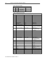
Table 4-5 (HART Initialization Sequence)
Commands sent at Initial device connection
Command: Definition:
Comment:
0
Read unique identifier.
Sent using “Short Address” to find device
6
Set Polling Address
Only sent if device responded at non 0 Addr
59
Write number of response preambles.
12
Read Message
13
Read tag, descriptor, and date.
15
PV upper and lower range values
16
Read final assembly Number.
48
Read Additional Device Status
50
Read dynamic variable assignments.
3 or 9
Read Dynamic Variables
Cmd 3 if HART rev 5, else Cmd 9 used
2
Read Loop Current
Only sent if Cmd 9 is being used
If the connected HART device’s configuration changes, the device will set the
”configuration changed” bit (i.e. bit 6 of the Field Device Status byte). When the IExCH
detects that the “configuration changed” bit is high, it will automatically re-send the
appropriate HART commands to refresh the device information stored in its cache
memory. See Table 4-6. The first command sent is command 38 which will reset the
“configuration changed” bit in the device.
The CFG (device configuration changed) bit was added to the IExCH input assembly to
User’s Manual Pub. 0300257-01 Rev. A
Chapter 4: IExCH and HART
4-7
notify the user when to send the Get HART Device Information message to retrieve the
cached data. See Table 3-4 and Table 3-5.
Table 4-6 (HART Refresh Sequence)
Commands sent to re-fresh Device Information on Configuration Change Detected
Command:
Definition:
Comment:
38
Reset Configuration Changed bit
12
Read Message
13
Read tag, descriptor, and date.
15
PV upper and lower range values
16
Read final assembly Number.
48
Read Additional Device Status
50
Read dynamic variable assignments.
The following table describes the class, service code and instances required to send the
Get HART Device Information message.
Table 4-7 (Get HART Device Information)
Unconnected Message
Field
Value
Definition
Message Type
Service Code
Class Name
Instance Name
Object Attribute
Request Size
Reply Size
“CIP Generic”
0x4D
0x035D
1-4
None, leave this field blank
0
2-120 bytes
(2) Size when Device information not
available
(120) Size when valid Device
Information returned
The following tables describe the possible message responses.
Table 4-8 (Request Data)
HART Get Device Information - Request packet structure
Get currently cached Device Information for a given channel.
Offset
Field
Value
Definition
No Request Data
User’s Manual Pub. 0300257-01 Rev. A
Get Device Information
HART Object
Selects channels 0 through 3
No Request Data
Number of Data bytes
returned
4-8
Point IO™ 2/4 Channel Analog HART Module
Table 4-9 (Request Failed)
HART Get Device Information - Reply packet structure
Offset
Field
Value
Definition
0
Status
Command status
1
Pad
34 = DR_RUNNING
35 = DR_DEAD
0
Pad byte
Table 4-10 (Request Succeeded)
HART Get Device Information - Reply packet structure
Offset
Field
Value
Definition
0
Status
00 = SUCCESS
Command status
1
Manufacture ID
(1 byte)
CMD#0, Byte 1
2
Device Type
(1 byte)
CMD#0, Byte 2
3
HART Preamble
(1 byte)
CMD#0, Byte 3
4
HART Univ Cmd Code
(1 byte)
CMD#0, Byte 4
5
HART Trans Spec Rev
(1 byte)
CMD#0, Byte 5
6
Software Revision
(1 byte)
CMD#0, Byte 6
7
Hardware Revision
(1 byte)
CMD#0, Byte 7
8
HART Flags
(1 byte)
CMD#0, Byte 8
9
Pad_1 for 32 bit alignment
(1 byte)
10-11
HART Manufacturer ID16 Bit
(2 byte)
12-15
HART Device ID Number
(4 bytes – UINT)
CMD#0,Byte 1 if HART rev < 7
CMD#0,Bytes 17-18 if HART rev
>= 7
CMD#0, Bytes 9-11
Bytes re-ordered into Intel
Format(LSB 1st ) from HART
format(MSB 1st).
16-19
Tag Size
8 (4 bytes)
20-27
Tag String
(8 bytes unpacked ASCII)
28-31
Descriptor Size
16 (4 bytes)
32-47
Descriptor String
(16 bytes unpacked ASCII)
48
Date Day
(1 byte)
CMD#13, Byte 18
49
Date Month
(1 byte)
CMD#13, Byte 19
50-51
Date Year
(2 bytes)
CMD#13, Byte 20 (+ 1900)
52-55
Final Assembly Number
(4 bytes – UINT)
CMD#16, Bytes 0-2
Bytes re-ordered into Intel
Format(LSB 1st) from HART
Format(MSB 1st).
56-59
Message Size
32 (4 bytes)
60-91
Message String
(32 bytes unpacked ASCII)
CMD#12, Bytes 0-23
92
PVCode
(1 byte)
93
SVCode
(1 byte)
94
TVCode
(1 byte)
95
FVCode
(1 byte)
96
PVUnits
(1 byte)
CMD#50, Bytes 0, 0xff if not
supported
CMD#50, Bytes 1, 0xff if not
supported
CMD#50, Bytes 2, 0xff if not
supported
CMD#50, Bytes 3, 0xff if not
supported
CMD#3, Byte 4
97
SVUnits
(1 byte)
CMD#3, Byte 9, 0 if not present
98
TVUnits
(1 byte)
CMD#3, Byte 14, 0 if not present
99
FVUnits
(1 byte)
CMD#3, Byte 19, 0 if not present
100
Transfer Function
(1 byte)
CMD#15, Byte 1
101
Range Units
(1 byte)
CMD#15, Byte 2
User’s Manual Pub. 0300257-01 Rev. A
CMD#13, Bytes 0-5
CMD#13, Bytes 6-17
Chapter 4: IExCH and HART
4-9
HART Get Device Information - Reply packet structure
Offset
Field
Value
Definition
102-103
Expanded Device Type Code
(2 bytes)
104-107
HART PV Lower Range
(4 bytes – Floating Point Value)
CMD#0, Byte 2 if HART Rev < 7
CMD#0, Bytes 1-2 if HART Rev
>= 7
CMD#15, Bytes 3-6
108-111
HART PV Upper Range
(4 bytes – Floating Point Value)
CMD#15, Bytes 7-10
112-115
Damping Value
(4 bytes – Floating Point Value)
CMD#15, Bytes 11-14
116
Write Protect Code
(1 byte)
CMD#15, Byte 15
117
Pad_2 for alignment
(1 byte)
118 - 119
Private Label Mfg 16Bit
(2 bytes)
CMD#0, Byte 1 if HART Rev < 7
CMD#0, Bytes 19-20 if HART
Rev >=7
Sending the Get HART Device Information Message
The following rung will send an unconnected message to read the HART device
Information.
This is the message configuration dialog box
Get HART Device
Info Service Code
HART Instance 1
for Channel 0
HART Object Class
4.3.3 HART Pass-through Messaging
The HART Pass-Through Command can be used to send any HART command including
universal, common practice or device specific, directly to a field device via ladder.
All HART pass-through commands require a series of messages to be exchanged. First, a
pass-through init must be sent to the HART module to initiate the pass-through
command. The HART module will respond to the request with a request reply that
includes a handle that can be used to obtain the pass-through message response. Once the
handle is received, the user may issue a pass-through query to obtain the status of the
User’s Manual Pub. 0300257-01 Rev. A
4-10
Point IO™ 2/4 Channel Analog HART Module
pass-through command and the pass-through response data, if available.
There is a handle timeout associated with the final reply message. After the HART
module obtains the requested information from the HART device, it will start a handle
timeout timer. Refer to section 3.5.4for information regarding how to set the handle
timeout. The reply message will be cached in memory during the handle timeout period.
When the handle timeout timer expires the reply message will be discarded, and another
pass through message will be serviced without being rejected. The user defined handle
timeout is in the range of 1 to 255 seconds.
!
Attention
If the HART message being sent or received using the pass-through
command contains double-words or floating point values, the order of
the bytes must be reversed.
Depending on the HART command, the data contained within the HART message may
include floating point numbers or double integers. If a floating point or double integer is
contained within the HART message, the user must be aware that the order of the bytes
that make up the float or double will need to be reversed. The reason for this is related to
how the bytes are stored in the PLC.
The PLC stores the bytes in memory in a format referred to as "little-endian". Littleendian is an order in which the "little end" (least significant value in the sequence) is
stored first (at the lowest storage address). However, HART devices transmit the byte
data in the reverse order or as you may have guessed "big-endian".
Pass-Through Init
The following table describes the class, service code and instances required to send the
Pass-through Request message.
Table 4-11 (Pass-through Init)
Unconnected Message
Field
Value
Definition
Message Type
Service Code
Class Name
Instance
Object Attribute
Request Size
Reply Size
“CIP Generic”
0x4E
0x035D
1-4
None, leave this field blank
2-257 bytes
4 bytes
Pass-through Request
HART Object
Selects channel 0-3
HART Data & Cmd
Number of Data bytes returned
The following tables describe the possible message responses.
Table 4-12 (Request Data)
HART Ladder Passthrough Init - Request packet structure
Offset
Field
Value
Definition
0
1
HART Command
HART Data Size
0-255 (1 byte)
0-255 (1 byte)
2-256
HART Data bytes
0-255 (1 byte)
HART Command Number
Number of Data bytes for selected HART
command
HART command data
User’s Manual Pub. 0300257-01 Rev. A
Chapter 4: IExCH and HART
4-11
Table 4-13 (Reply Data)
HART Ladder Passthrough Init - Reply packet structure
Offset
Field
Value
Definition
Unconnected Message Header
0
Status
32 = Busy (Queues full)
33 = DR_INITIATE
(passthrough success)
35 = DR_DEAD
1
2
3
HART
Command
Handle
0-255 (1 byte)
1-255 (1 byte)
Queue Space
Remaining
OR
“Reason Code”
if status = 35
Command Status
Note: HART Cmds
59,107,108, & 109 are not
allowed and will always
return DR_DEAD.
Echo of HART command
Handle used in Query
operation
Number of queues still
available for this channel.
OR
Reason Code is a diagnostic
value returned when message
fails(Status = 35)
(1 byte)
Pass-through Query
The following table describes the class, service code and instances required to send the
Pass-through Query message.
Table 4-14 (Pass-through Query)
Unconnected Message
Field
Value
Definition
Message Type
Service Code
Class Name
Instance
Object Attribute
Request Size
Reply Size
“CIP Generic”
0x4F
0x035D
1-4
None, leave this field blank
1 byte
6-260 bytes
Passthrough Init
HART Object
Selects channel 0-3
Handle for Query
Number of Data bytes returned
The following tables describe the possible message responses.
Table 4-15 (Request Data)
HART Ladder Passthrough Query - Request packet structure
Offset
Field
Value
Definition
0
Handle
1-255 (1 byte)
Handle for Query
User’s Manual Pub. 0300257-01 Rev. A
4-12
Point IO™ 2/4 Channel Analog HART Module
Table 4-16 (Reply Data)
HART Ladder Passthrough Query - Reply packet structure
Offset
Field
Value
Definition
0
Status
Query Status
1
2
3
HART Command
HART CommStatus
HART FieldDeviceStatus
OR
Reason Code if status = 35
00 = Success
34 = DR_RUNNING
35 = DR_DEAD
0-255 (1 byte)
(1 byte)
(1 byte)
4
Data Size
5-257
HART Reply Data …
0-255 (1 byte)
Echo of HART command
HART Reply Status Byte #1
HART Reply Status Byte #2
Reason Code is a diagnostic
value returned when message
fails(Status = 35)
Number of Data bytes in
reply for HART command
Data bytes returned in data
field of HART reply to
requested command
HART Pass-through “Reason Code” definitions
The HART Pass-through “Reason Code” is a value that is reported when a Pass-through
reply message returns the general “Status” value as 35 (DR_DEAD). It provides the user
a diagnostic code, which is referenced in the table below, describing the possible cause of
the failure. This code will be returned in offset 3 of the reply message for Pass-through
Init or Query messages whenever the “Status” value at offset 0 is equal to 35
(DR_DEAD).
Table 4-17 (Reason Codes)
HART Pass-through Reason Code
Value
Definition
0x81
0x82
0x83
0x84
No response from HART device
Invalid long frame address
Invalid HART message checksum
HART Command not allowed
(blocked by module)
Invalid Channel selected
Channel is not HART Enabled
Channel does not have a device
connected
Size of CIP message too small to
hold size of HART message
0x85
0x86
0x87
0x89
0x8A
0x8B
Invalid Handle
Invalid Start Delimiter
Notes:
Module has not established HART
communications on this channel
Module looks at HART Data size field in
request and validates that the incoming CIP
message size is large enough to send all the
data
Only applies to a Query message
Sending a Pass-through Message
The ladder on the following page demonstrates how to send a complete Pass-through
message using ladder. This example sends universal HART command 1 (Read Primary
Variable). For a listing of HART Universal and Common practice commands, see
Appendix B.
User’s Manual Pub. 0300257-01 Rev. A
Chapter 4: IExCH and HART
Figure 4-3 (HART Pass-through)
User’s Manual Pub. 0300257-01 Rev. A
4-13
4-14
Point IO™ 2/4 Channel Analog HART Module
4.3.4 Flush Queue
The Flush Queue message can be sent to have the IExCH module discard any pending
HART replies awaiting a query command. These replies are automatically discarded
once the handle timeout period has expired. The handle timeout period is defined in the
module configuration. The default value assigned by the AOP is 20 seconds. Unless you
need to discard the replies faster than 20 seconds, you won't need to use this Flush Queue
command.
The following table describes the class, service code and instances required to send the
Flush Queue message.
Table 4-18 (Flush Queue)
Unconnected Message
Field
Value
Message Type
Service Code
Class Name
Instance
“CIP Generic”
0x50
0x035D
0-3
0 = All Channels
1-4 = Single Channel (0-3)
None, leave this field blank
0
0
Object Attribute
Request Size
Reply Size
Definition
Flush Queues
HART Object
All channels at once or a single channel
No Request Data
Number of Data bytes returned
4.3.5 Suspend HART Communication
The “suspend HART communication" message, will temporarily suspend all HART
communication on one or more channels for up to 3 minutes. HART communication will
resume automatically under the following conditions:
•
After 3 minutes
•
If the HART configuration changes during the three minute timeout period
•
If the “resume HART communication” message is issued.
The following table describes the class, service code and instances required to send the
Suspend HART Communication message.
Table 4-19 (Suspend HART Communication)
Unconnected Message
Field
Value
Message Type
Service Code
Class Name
Instance
“CIP Generic”
0x51
0x035D
0-3
0 = All Channels
1-4 = Single Channel
None, leave this field blank
0
2
Object Attribute
Request Size
Reply Size
User’s Manual Pub. 0300257-01 Rev. A
Definition
Suspend HART
HART Object
All channels suspended or a single channel
No Request Data
Number of Data bytes returned
Chapter 4: IExCH and HART
4-15
The following tables describe the possible message responses.
Table 4-20 (Request Data)
Suspend Normal HART acquisitions - Request packet structure
Offset
Field
Value
Definition
No Request Data
Table 4-21 (Reply Data)
Suspend Normal HART acquisitions - Reply packet structure
Offset
Field
Value
Definition
0
Status
1
Pad
(1 byte)
00 = SUCCESS
35 = DR_DEAD
0
4.3.6 Resume HART Communication
Used in conjunction with the HART suspend message, allows the user to resume HART
communication on a channel or channels if HART communication is currently
suspended.
The following table describes the class, service code and instances required to send the
Resume HART Communication message.
Table 4-22 (Resume HART Communication)
Unconnected Message
Field
Value
Message Type
Service Code
Class Name
Instance
“CIP Generic”
0x52
0x035D
0-3
0 = All Channels
1-4 = Single Channel
None, leave this field blank
0
2
Object Attribute
Request Size
Reply Size
Definition
Resume HART
HART Object
All channels resume or a single channel
No Request Data
Number of Data bytes returned
The following tables describe the possible message responses.
Table 4-23 (Request Data)
Resume Normal HART acquisitions - Request packet structure
Offset
Field
0
User’s Manual Pub. 0300257-01 Rev. A
Value
Definition
No Request Data
4-16
Point IO™ 2/4 Channel Analog HART Module
Table 4-24 (Reply Data)
Resume Normal HART acquisitions - Reply packet structure
Offset
Field
Value
0
Status
1
Pad
(1 byte)
00 = SUCCESS
35 = DR_DEAD
0
User’s Manual Pub. 0300257-01 Rev. A
Definition
Appendix A
Module Specifications
General Specifications
Parameter
1734sc-IE4CH
Specification
1734sc-IE2CH
Specification
Module location
1734-TBxx
Pointbus current
15 mA
Power dissipation
0.6 W maximum @ 28.8V dc
Thermal dissipation
2.0 BTU/hr maximum @ 28.8V dc
Isolation Voltage
50V (continuous), Basic Insulation Type,
No isolation between channels
External DC power
Supply Voltage
Voltage Range
Supply Current
24V DC nominal
10..28.8V DC
20 mA @24V DC
24V DC nominal
10..28.8V DC
19 mA @24V DC
Dimensions (HxWxD), approx. 56 x 12 x 75.5 mm (2.21 x 0.47 x 2.97 in.)
Keyswitch position
3
Enclosure type rating
None (open-style)
Wire size
Determined by installed terminal block
Wiring category
2 – on signal ports
Wire type
Shielded
Terminal base screw torque
Weight, approx.
Determined by installed terminal block
35g (1.235 oz)
Input Specifications
Parameter
Number of Inputs
Resolution
Input current terminal
1734sc-IE4CH
Specification
1734sc-IE2CH
Specification
4 single ended, non-isolated
2 single ended, non-isolated
16 bits
4..20 mA limit: 3.42-20.58mA
Absolute accuracy
+/- 20 uA @ 25°C
Repeatability
+/- 5 uA @ 25°C
Accuracy drift w/temp.
User’s Manual Pub. 0300257-01 Rev. A
50uA max -20..55°C, 30ppm / °C typical
A-2
Point IO™ 2/4 Channel Analog HART Module
Input update rate
(per module)
Input Impedance
ADC Type
488 ms @ Notch=50/60Hz (def)
248 ms @ Notch=50Hz
208 ms @ Notch=60Hz
128 ms @ Notch=100Hz
108 ms @ Notch=120Hz
58 ms @ Notch=240Hz
33 ms @ Notch=480Hz
248 ms @ Notch=50/60Hz (def)
128 ms @ Notch=50Hz
108 ms @ Notch=60Hz
68 ms @ Notch=100Hz
58 ms @ Notch=120Hz
33 ms @ Notch=240Hz
21 ms @ Notch=480Hz
250 ohms +/-1% (input 0-21 mA)
Sigma Delta
CMRR
>96dB Typical
NMRR
- 60dB point of first notch
47 Hz @ Notch=50/60Hz (default)
45 Hz @ Notch=50Hz
54 Hz @ Notch=60Hz
91 Hz @ Notch=100Hz
109 Hz @ Notch=120Hz
221 Hz @ Notch=240Hz
446 Hz @ Notch=480Hz
Data Format
Maximum overload
Signed integer
Fault protected to 28.8V DC
Calibration
Factory calibrated, user calibration supported
Indicators
1 green/red module status LED 1 green/red module status LED
1 green/red network status LED 1 green/red network status LED
2 green/red input status LEDs
4 green/red input status LEDs
User’s Manual Pub. 0300257-01 Rev. A
Appendix A: IExCH Specifications
A-3
Environmental Specifications
Environmental Tests
Industry Standards
Test Level Limits
IEC60068-2-1: (Test Ad, Operating Cold),
Temperature (Operating)
-20 to 55°C (-4 to 131°F)
IEC60068-2-2: (Test Bd, Operating Dry Heat),
(Performance Criteria A)
(natural convection cooling)
IEC60068-2-14: (Test Nb, Operating Thermal Shock)
IEC60068-2-1:
(Test Ab, Unpackaged Non-operating Cold),
Temperature
IEC60068-2-2:
-40 to 85°C (-40 to 185°F)
(Non-operating)
(Test Bb, Unpackaged Non-operating Dry Heat),
(Performance Criteria B)
IEC60068-2-14:
(Test Na, Unpackaged Non-operating Thermal Shock)
Humidity (Operating)
IEC60068-2-30:
(Performance Criteria A) (Test Db, Unpackaged Damp Heat):
80 - 95% Condensing
20-60-20°C Temp Cycle
Vibration (Operating)
IEC60068-2-6: (Test Fc, Operating)
(Performance Criteria A)
10 to 500Hz, 5g
Shock (Operating)
IEC60068-2-27: (Test Ea, Unpackaged Shock)
(Performance Criteria A)
30 g,11ms half-sine (3 mutually
perpendicular axes)
Shock (Non-operating)
IEC60068-2-27: (Test Ea, Unpackaged Shock)
(Performance Criteria B)
50 g, 11ms half-sine (3 mutually
perpendicular axes)
Packaged Vibration
ES# PC003, Revision A
5 to 20 Hz 1 g. 1 hour each axis. 4
min sweep.
Packaged Shock
("drop test")
ES# PC004, Revision A
Drop from 48 in. 10 times each in
various orientations.
Radiated Emissions
CSIPR 11; Group 1, Class A
(Enclosure) Class A
Conducted Emissions
IEC 61000-6-4:2007
Group 1, Class A (AC Mains)
IEC 61000-4-2
Rockwell Document QTP#X0327
6kV Indirect (Coupling Plate)
6kV Contact Discharge ( to points of
initial contact)
8kV Air Discharge ( to points of
initial contact)
Radiated RF immunity
IEC 61000-4-3: Level 3
(Performance Criteria A) Rockwell Document QTP#X0327
10 V/M with 1 kHz sine-wave
80%AM from 80…2000 MHz
10 V/M with 200 Hz sine-wave 50%
Pulse 100%AM @900 MHz
10 V/M with 200 Hz sine-wave 50%
Pulse 100%AM @1890 MHz
1 V/M with 1 kHz sine-wave
80%AM from 2000…2700 MHz
EFT/B immunity
(Performance Criteria B)
± 3 kV @ 5 kHz for 5 minutes on
communication ports and power
ports
± 3 kV @ 5 kHz for 5 minutes on
(PE) ground port
ESD immunity
(Performance Criteria B)
IEC 61000-4-4*
Rockwell Document QTP#X0327
Surge transient immunity IEC 61000-4-5
(Performance Criteria A) Rockwell Document QTP#X0327
±- 2 kV line-earth {CM}@ 2Ω on
communications ports
± 2kV CM @ 42Ω, ±1kV DM @
42Ω on unshielded ports
Conducted RF immunity IEC 61000-4-6
(Performance Criteria A) Rockwell Document QTP#X0327
10V rms with 1 kHx sine wave
80%AM from 150 kHz…80
MHz on communications, power
ports and (PE) ground
Magnetic Field
Not Applicable
AC Mains Voltage Dips,
Interruptions and
Variations
Not Applicable
DC Mains Voltage Dips,
Interruptions and
Variations
Not Applicable
Oscillatory Waves
C-Tick (Australia)
User’s Manual Pub. 0300257-01 Rev. A
Not Applicable
AS/NZS CISPR 11 (Group 1, Class A)
Class A
A-4
Point IO™ 2/4 Channel Analog HART Module
Agency Certifications
The following certifications will be obtained at 1st production release.
UL 508
ISA 12.12.01
CUL
Operating Temperature Code T4
CE compliance to EN 61010-1 and EN 61131-2
Atex 4.4
ODVA DeviceNet Compliance
EX nA IIC Gc
II 3G
-20C < Ta < 55C
DEMKO 11 ATEX 1103434U
ATEX Special Conditions for Safe Use
•
Provisions shall be made to prevent the rated voltage being exceeded by the
transient disturbances of more than 140%.
•
The system shall be mounted in an ATEX certified enclosure with a minimum
ingress protection rating of at least IP54 as defined in IEC60529 or EN60529
and used in an environment of not more than pollution degree 2.
•
These modules must be used with the ATEX certified terminal module 1734-TB
by Allen-Bradley.
User’s Manual Pub. 0300257-01 Rev. A
Appendix B
Additional HART
Protocol Information
This appendix describes the HART protocol and provides references for additional
information about the protocol. Consult the HART protocol specification and vendor
provided documentation for specifics on HART commands.
This appendix provides the following:
•
HART protocol background information
•
Common practice command sets
•
Extended command sets
•
References to additional information
HART Field Communication Protocol is widely accepted in the industry as the standard
for digitally enhanced 4…20mA communication with smart field instruments. The
HART Protocol message structure, command set, and status are discussed in this
appendix.
The HART command set is organized into these groups and provides read and write
access to a wide array of information available in smart field instruments:
•
Universal commands provide access to information that is useful in normal plant
operation such as the instrument manufacturer, model, tag, serial number,
descriptor, range limits, and process variables. All HART devices must
implement universal commands.
•
Common practice commands provide access to functions that can be carried out
by many devices.
•
Device specific commands provide access to functions that can be unique to a
particular device.
Section B.1
Message
Structure
Read this section for a description of transaction procedure, character coding, and
message structure of the HART protocol. These correspond to layer 2 (datalink layer) of
the OSI protocol reference model.
B.1.1 Master-slave Operation
HART is a master-slave protocol. This means that each message transaction is originated
by the master; the slave (field) device replies when it receives a command message
addressed to it. The reply from the slave device acknowledges that the command was
received and can contain data requested by the master.
B.1.2 Multiple Master Operation
The HART protocol provides for two active masters in a system: one primary and one
secondary. The two masters have different addresses. Each can positively identify replies
User’s Manual Pub. 0300257-01 Rev. A
B-2
Point IO™ 2/4 Channel Analog HART Module
to its own command messages. The 1734sc-IE2CH or 1734sc-IE4CH module acts as
primary master. A secondary master, such as a handheld configuration device, may also
be connected.
B.1.3 Transaction Procedure
HART is a half-duplex protocol. After completion of each message, the FSK carrier
signal must be switched off to let the other station transmit. The carrier control timing
rules state that the carrier should be turned on not more than 5 bit times before the start of
the message (that is, the preamble) and turned off not more than 5 bit times after the end
of the last byte of the message (the checksum).
The master is responsible for controlling message transactions. If there is no reply to a
command within the expected time, the master should retry the message. After a few
retries, the master should abort the transaction, because presumably the slave device or
the communication link has failed.
After each transaction is completed, the master should pause for a short time before
sending another command, to provide an opportunity for the other master to break in if it
wishes. This way, two masters (if they are present) take turns at communicating with the
slave devices. Typical message lengths and delays allow two transactions per second.
B.1.4 Burst Mode
Burst mode is not supported.
Section B.2
Response Code
and Field Device
Status
Two bytes of status also called the response code and field device status are included in
every reply message from a field or slave device. These two bytes convey
communication errors, command response problems, and field device status. If an error
is detected in the outgoing communication, the most significant bit (bit 7) of the first byte
is set to 1 and the details of the error are reported in the rest of that byte. The second
byte, in this case, is all zeros.
Communication errors are typically those that would be detected by a UART (parity
overrun and framing errors). The field device also reports overflow of its receive buffer
and any discrepancy between the message content and the checksum received.
In RSLogix 5000 software, if the leftmost bit of the ResponseCode is set, it displays a
negative number. In this case, the ResponseCode represents a communication fault.
Change the display format to hexadecimal to interpret communication status.
If the leftmost bit of the ResponseCode is 0 (value 0…127), then there was no
communication error and the value is a ResponseCode from the HART field device.
Response codes indicate if the device performed the command. 0 means no error. Other
values are errors or warnings. To understand the ResponseCode, contact your HART
field device manufacturer or the HART specification.
See Table B-1and Table B-2 for descriptions of the response code and the field device
status.
Table B-1 (Response Codes – HART Device Status Byte 1)
Response Code
If Bit 7 is
1
And Bits
6…0 are
16#40
User’s Manual Pub. 0300257-01 Rev. A
Description
Parity Error
Vertical parity error - The parity of one or more of the
bytes received by the device was not odd
Appendix B: Additional HART Protocol Information
Response Code
If Bit 7 is
B-3
Description
1
And Bits
6…0 are
16#20
1
16#10
1
16#08
1
16#04
1
16#02
1
0
0
0
0
0
0
0
0
16#01
0
1
3
4
5
6
7
8
0
9
0
10
0
11
0
0
0
0
0
0
12
13
14
16
32
64
Overrun Error
Overrun error - At least one byte of data in the receive
buffer of the UART was overwritten before it was read
(for example, the slave did not process incoming byte fast
enough)
Framing Error
Framing error - The Stop Bit of one or more bytes
received by the device was not detected by the UART (for
example, a mark or 1 was not detected when a Stop Bit
should have occurred)
Checksum Error
Longitudinal parity error -The Longitudinal Parity
calculated by the device did not match the Check Byte at
the end of the message
(Reserved)
Reserved - Set to zero
Buffer overflow -The message was too long for the
RX Buffer Overflow
receive buffer of the define
(undefined)
Reserved - Set to zero
No command specific error
(undefined)
Value too large
Value too small
Not enough bytes in command
Transmitter-specific command error
In Write-protect mode
Update Failed - Update In Progress - Set to Nearest Possible Value
Applied Process Too High - Lower Range Value Too High - Not In Fixed Current
Mode
Applied Process Too Low - Lower Range Value Too Low - MultiDrop Not
Supported
In MultiDrop Mode - Invalid Transmitter Variable Code - Upper Range Value Too
High
Invalid Unit Code -Upper Range Value Too Low
Both Range Values Out of Limits
Pushed Upper Range Value Over Limit - Span Too Small
Access restricted
Device busy
Command not implemented
If no error was detected in the outgoing communication, the second byte contains status
information pertaining to the operational state of the field or slave device.
Table B-2 (Field Device Status – HART Device Status Byte 2)
Bit
Bit Mask
7
16#80
6
5
16#40
16#20
4
16#10
3
16#08
2
16#04
1
16#02
0
16#01
Definition
Device malfunction - The device detected a serious error or failure that compromises device
operation
Configuration changed -An operation was performed that changed the device’s configuration
Cold start - A power failure or device reset occurred
More status available - More status information is available via command 48, Read
Additional Status Information
Loop current fixed - The loop current is being held at a fixed value and is not responding to
process variations
Loop current saturated - The loop current has reached its upper or lower endpoint limit and
cannot increase or decrease any further
Non-primary variable out of limits - A device variable not mapped to the PV is beyond its
operating limits
Primary variable out of limits - The PV is beyond its operating limit
Note: 16# means this number is in Hex.
User’s Manual Pub. 0300257-01 Rev. A
B-4
Point IO™ 2/4 Channel Analog HART Module
Table B-3 (HART Universal Commands)
Command
No
Function
.
0
Read
Unique
Identified
1
2
3
6
11
12
13
14
15
16
17
Write
polling
address
Read unique
identifier
associated
with tag
Read
message
Read tag,
descriptor,
date
Read PV
sensor
information
Data in Reply
Byte
Data
Type
0
1
2
3
4
5
6
7
8
9…11
254 (expansion)
Manufacturer identification code
Manufacturer device type code Number of
preambles required Universal command
revision
Device-specific command revision
Software revision
Hardware revision
(2)
Device function flags
Device ID number
(H)
(B)
0
1…4
PV units code Primary variable
None
0…3
4…7
Current (mA)
Primary variable %
None
0…3
4
5…8
9
10…13
14
15…18
19
20…23
Current (mA)
PV units code
Primary variable
SV units code
Secondary variable
TV units code
Third variable
FV units code
(3)
Fourth variable
As in command
0…11
As in command 0
Type
None
Read
primary
variable
Read
current and
percent of
range
Read
current and
four
(predefined)
dynamic
variables
0
Polling
address
0…5
Tag
(A)
None
Read output
information
Read final
assembly
number
Write
message
18
None
0…23
0…5
Write tag,
descriptor,
date
19
Data in Command
Byte
Data
Write final
assembly
6…17
18…20
0…2
Message
(32 characters)
Tag
(8 characters)
Descriptor
(16 characters)
Date
(A)
Final assembly
number
(B)
(A)
(A)
(D)
User’s Manual Pub. 0300257-01 Rev. A
(1)
(F)
(F)
(F)
(1)
Contained in
Input CIP
Tag
MSG
x
x
x
x
x
x
x
x
x
x
x
x
x
x
x
x
x
x
x
x
x
x
x
x
x
x
x
x
x
x
0…23
Message (32 characters)
(A)
x
0…5
6…17
18…20
0…2
3
4…7
8…11
12…15
0
1
2
3…6
7…10
11…14
15
16
0…2
Tag (8 characters)
Descriptor (16 characters)
Date
Sensor serial number
Units code for sensor limits and min span
Upper sensor limit
Lower sensor limit
Min span
Alarm select code
Transfer function code
PV/range units code
Upper range value
Lower range value
Damping value (seconds)
Write-protect code
Private-label distributor code
Final assembly number
(A)
(A)
(D)
(B)
x
x
x
As in command
(F)
(F)
(F)
(F)
(F)
(F)
(B)
x
x
x
x
x
x
x
Appendix B: Additional HART Protocol Information
Command
No
Function
.
number
Data in Command
Byte
Data
Type
(1)
Data in Reply
Byte
Data
B-5
Type
(1)
(5)
Device-specific status
S
Operational modes
Standardized status 0
Standardized status 1
Analog channel saturated
Standardized status 2
Standardized status 3
(4)
Analog channel fixed
Device-specific status
(1) (A) = Packed ASCII, (B) = 3-byte integer, (D) = Date, (F) = Floating Point (HART format), (H) = HART flag
(2) Bit 6 = multisensor device. Bit 1 = EEPROM control required. Bit 2 = protocol bridge device.
(3) Truncated after last supported variable.
(4) 24 bits each LSB…MSB refers to A0 #1…24.
(5) Sint []
48
Read
additional
device
status
Starting in
HART
version 7, the
data
in the command
could be the
same
as in the reply.
Contained in
Input CIP
Tag
MSG
x
x
x
x
x
x
x
x
x
0…5
6…7
8
9
10
11
12
13
14…24
Table B-4 (Common Practice Commands)
Command
No. Function
33
34
35
36
37
38
39
40
41
Data in Command
Byte
Data
Read
transmitter
variables
Write
damping
value
Write range
values
Set upperrange value
(= push
SPAN
button)
Set lowerrange value
(= push
ZERO
button)
Reset
‘configurati
on
changed’
flag
EEPROM
control
Enter/exit
Fixed
Current
mode
Perform
device selftest
Type
None
0…3
Damping value
(seconds)
0
1…4
5…8
Range units code
Upper-range value
Lower-range value
None
0
0…3
EEPROM control
code(3)
Current (mA)
(6)
Data in Reply
Byte
Data
0
1
2…5
6
7
8…11
12
13
14…17
18
19
20…23
(F)
Transmitter variable code, slot 0
Units code for slot 0
Variable for slot 0
Transmitter variable code, slot 1
Units code for slot 1
Variable for slot 1
Transmitter variable code, slot 2
Units code for slot 2
Variable for slot 2
Transmitter variable code, slot 3
Units code for slot 3
(7)
Variable for slot 3
As in command
(F)
(F)
As in command
As in command
(1)
None
User’s Manual Pub. 0300257-01 Rev. A
(F)
(F)
(F)
(F)
(F)
(F)
None
(F)
Type
None
(6)
Contained in
Input
CIP
Tag
MSG
B-6
Point IO™ 2/4 Channel Analog HART Module
Command
No. Function
Data in Command
Byte
Data
42
43
44
45
46
47
48
49
50
51
Perform
master reset
Set (trim)
PV zero
Write PV
units
Trim DAC
zero
Trim DAC
gain
Write
transfer
function
Read
additional
device
status
Write PV
sensor
serial
number
Read
dynamic
variable
assignment
s
Write
dynamic
variable
assignment
s
0
PV units code
0…3
Measured current
(mA)
0…3
0
0…2
1
2
3
52
53
54
55
56
57
Set
transmitter
variable
zero
Write
transmitter
variable
units
Read
transmitter
variable
information
0
Write
transmitter
variable
damping
value
Write
transmitter
variable
sensor
serial
number
Read unit
tag,
description,
date
0
0
1
0
1…4
0
1…3
(6)
Data in Reply
Byte
Data
Type
(6)
Contained in
Input
CIP
Tag
MSG
As in command
(F)
Transfer function
code
Moved to Universal
Commands in
HART version 7.
See 48 in Universal Commands
Sensor serial
number
As in command
None
0
Type
0
1
2
3
PV transmitter variable code
SV transmitter variable code
TV transmitter variable code
FV transmitter variable code
PV transmitter
variable code
SV transmitter
variable code
TV transmitter
variable code
FV transmitter
variable code
Transmitter variable
code
As in command
Transmitter variable
code
Transmitter var.
units code
Transmitter variable
code
Transmitter variable
code
Transmitter variable
damping value (sec)
0
1…3
4
5…8
9…12
13…16
User’s Manual Pub. 0300257-01 Rev. A
Transmitter variable code
Transmitter variable sensor serial
Transmitter var. limits units code
Transmitter variable upper limit
Transmitter variable lower limit
Transmitter var. damping value (sec)
(F)
(F)
(F)
As in command
(F)
Transmitter variable
code
Transmitter variable
sensor serial #
None
x
x
x
x
As in command
0…5
6…17
18…20
Unit tag
Unit descriptor
Unit date
(A)
(A)
(D)
x
x
x
Appendix B: Additional HART Protocol Information
Command
No. Function
Data in Command
Byte
Data
Type
58
Write unit
tag,
descriptor,
date
0…5
6…17
18…20
Unit tag
Unit descriptor
Unit date
(A)
(A)
(D)
59
Write
number of
response
preambles
Read
analog
output and
percent of
range
Read
dynamic
variables
and
PV analog
output
0
Number of response
preambles
0
Analog output
number code
0
1
2…5
6…9
Analog output number code
Analog output units code
Analog output level
Analog output percent of range
None
0
1…4
5
6…9
10
11…14
15
16…19
20
21…24
PV analog output units code
PV analog output level
PV units code
Primary variable
SV units code
Secondary variable
TV units
Tertiary variable
FV units code
Fourth variable
60
61
62
Read
analog
outputs
0
1
2
3
63
64
Read
analog
output
information
Write
analog
output
(2)
0
0
1…4
Analog output
number;
code for slot 0
Analog output
number;
code for slot 1
Analog output
number;
code for slot 2
Analog output
number; code for
(4)
slot 3
User’s Manual Pub. 0300257-01 Rev. A
Data in Reply
Byte
Data
Slot 0 analog output number code
Slot 0
Slot 0 level
Slot 1
Slot 1
Slot 1 level
Slot 2
Slot 2
Slot 2 level
Slot 3
Slot 3
(8)
Slot 3 level
0
1
2
3
4…7
8…11
12…15
Analog output number code
Analog output alarm select code
Analog output transfer function code
Analog output range units code
Analog output upper-range value
Analog output lower-range value
Analog output additional damping
value (seconds)
As in command
(F)
Type
(6)
Contained in
Input
CIP
Tag
MSG
As in command
0
1
2…5
6
7
8…11
12
13
14…17
18
19
20…23
Analog output
number code
Analog output
number code
Analog output
(6)
B-7
(F)
(F)
x
(F)
x
(F)
x
(F)
x
(F)
(F)
(F)
(F)
(F)
(F)
(F)
x
x
x
x
x
x
x
x
B-8
Point IO™ 2/4 Channel Analog HART Module
Command
No. Function
Data in Command
Byte
Data
65
additional
damping
value
Write
analog
output
range
value
0
1
2…5
66
Enter/exit
Fixed
Analog
Output
mode
0
1
2…6
67
Trim
analog
output zero
0
1
2…6
Trim
analog
output gain
0
1
2…6
69
70
107
(6)
Data in Reply
Byte
Data
additional damping
value (seconds)
6…9
68
Type
Write
analog
output
transfer
function
Read
analog
output
endpoint
values
0
Write Burst
mode
transmitter
variables
(for
command
33)
0
1
0
1
2
3
Analog output
number code
Analog output
range units code
Analog output
upper-range value
Analog output
lower-range value
Analog output
number code
Analog output units
code Analog output
(5)
level
Analog output
number code
Analog output units
code
Externally
measured analog
output level
Analog output
number code
Analog output units
code
Externally
measured analog
output level
Analog output
number code
Analog output
transfer function
code
Analog output
number code
Transmitter variable
code for slot 0
Transmitter variable
code for slot 1
Transmitter variable
code for slot 2
Transmitter variable
code for slot 3
User’s Manual Pub. 0300257-01 Rev. A
(F)
(F)
(F)
(F)
(F)
0
1
2…5
6…9
Analog output number code
Analog output endpoint units code
Analog output upper endpoint value
Analog output lower endpoint value
As in command
Type
(6)
Contained in
Input
CIP
Tag
MSG
Appendix B: Additional HART Protocol Information
Command
Data in Command
No.
Function
Byte
Data
108
Write Burst
mode
command
number
Burst mode
control
0
Burst mode
command number
0
Burst mode control
code (0 = exit, 1 =
enter)
None
109
110
(1)
(2)
(3)
(4)
(5)
(6)
(7)
(8)
Read all
dynamic
variables
B-9
Data in Reply
Type
(6)
Byte
Data
Contained in
Type
(6)
Input
Tag
CIP
MSG
As in command
0
1…4
5
6…9
10
11…14
15
16…19
PV units code
PV value
SV units code
SV value
TV units code
TV value
FV units code
FV value
(F)
x
(F)
x
(F)
x
(F)
x
x
x
x
x
x
x
x
x
0 = exit Fixed Current mode.
Truncated after last requested code.
0 = burn EEPROM, 1 = copy EEPROM to RAM.
Truncated after last requested code.
Not a number exits Fixed-output mode.
(A) = Packed ASCII, (B) = 3-byte integer, (D) = Date, (F) = Floating Point (HART format), (H) = HART flag
Truncated after last requested code.
Truncated after last requested variable.
Section B.3
HART PV, SV,
TV, and FV
Status
HART PV, SV, TV, and FV are dynamic variables that contain the values of device
variables, which are various direct or indirect process measurements performed by the
HART field device.
Some devices let a set of their internal device variables be mapped to the PV, SV, TV,
FV dynamic variables that are automatically collected in the 1734sc-IExCH Input Tag.
HART PVStatus, SVStatus, TVStatus, FVStatus are known as Device Variable Status
values. These Status values are composed of groups of bits that indicate the quality of the
associated device variable.
User’s Manual Pub. 0300257-01 Rev. A
B-10
Point IO™ 2/4 Channel Analog HART Module
Table B-5 (HART PV, SV, TV, and FV Status Values)
HART PV, SV, TV FV Status Values
Decimal
0
0
00000000
1
1
00000001
2
2
00000010
3
3
00000011
4
4
00000100
5
5
00000101
6
6
00000110
7
7
00000111
8
8
00001000
9
9
00001001
10
A
00001010
11
B
00001011
12
C
00001100
13
D
00001101
14
E
00001110
15
F
00001111
16
10
00010000
17
11
00010001
18
12
00010010
19
13
00010011
20
14
00010100
21
15
00010101
22
16
00010110
23
17
00010111
24
18
00011000
25
19
00011001
26
1A
00011010
27
1B
00011011
28
1C
00011100
29
1D
00011101
30
1E
00011110
31
1F
00011111
32
20
00100000
33
21
00100001
34
22
00100010
35
23
00100011
36
24
00100100
37
25
00100101
38
26
00100110
39
27
00100111
40
28
00101000
41
29
00101001
42
2A
00101010
43
2B
00101011
44
2C
00101100
45
2D
00101101
Quality
Limit
More Status Available?
00
00
00
00
00
00
00
00
00
00
00
00
00
00
00
00
00
00
00
00
00
00
00
00
00
00
00
00
00
00
00
00
00
00
00
00
00
00
00
00
00
00
00
00
00
00
00
00
00
00
00
00
00
00
00
00
00
00
00
00
00
00
01
01
01
01
01
01
01
01
01
01
01
01
01
01
01
01
10
10
10
10
10
10
10
10
10
10
10
10
10
10
0
0
0
0
0
0
0
0
1
1
1
1
1
1
1
1
0
0
0
0
0
0
0
0
1
1
1
1
1
1
1
1
0
0
0
0
0
0
0
0
1
1
1
1
1
1
Bad
Bad
Bad
Bad
Bad
Bad
Bad
Bad
Bad
Bad
Bad
Bad
Bad
Bad
Bad
Bad
Bad
Bad
Bad
Bad
Bad
Bad
Bad
Bad
Bad
Bad
Bad
Bad
Bad
Bad
Bad
Bad
Bad
Bad
Bad
Bad
Bad
Bad
Bad
Bad
Bad
Bad
Bad
Bad
Bad
Bad
Not Limited
Not Limited
Not Limited
Not Limited
Not Limited
Not Limited
Not Limited
Not Limited
Not Limited
Not Limited
Not Limited
Not Limited
Not Limited
Not Limited
Not Limited
Not Limited
Low Limited
Low Limited
Low Limited
Low Limited
Low Limited
Low Limited
Low Limited
Low Limited
Low Limited
Low Limited
Low Limited
Low Limited
Low Limited
Low Limited
Low Limited
Low Limited
High Limited
High Limited
High Limited
High Limited
High Limited
High Limited
High Limited
High Limited
High Limited
High Limited
High Limited
High Limited
High Limited
High Limited
No
No
No
No
No
No
No
No
Yes
Yes
Yes
Yes
Yes
Yes
Yes
Yes
No
No
No
No
No
No
No
No
Yes
Yes
Yes
Yes
Yes
Yes
Yes
Yes
No
No
No
No
No
No
No
No
Yes
Yes
Yes
Yes
Yes
Yes
Device Family Specific
Hex Binary Binary
000
0
001
1
010
2
011
3
100
4
101
5
110
6
111
7
000
0
001
1
010
2
011
3
100
4
101
5
110
6
111
7
000
0
001
1
010
2
011
3
100
4
101
5
110
6
111
7
000
0
001
1
010
2
011
3
100
4
101
5
110
6
111
7
000
0
001
1
010
2
011
3
100
4
101
5
110
6
111
7
000
0
001
1
010
2
011
3
100
4
101
5
Decimal
Note: that this Device Variable Status byte is a new HART feature in HART
protocol revision 6 and many HART devices do not yet support it. For those
devices, the module creates a status value based on the communication
status of the device.
If the PV, SV, TV, FV are being collected without communication errors, the
value is set to 16#C0, indicating Good, Not Limited. Otherwise, the value is
set to 0, indicating Bad, Not Limited, no specific information available.
User’s Manual Pub. 0300257-01 Rev. A
Appendix C
Manufacturer
Identification Codes
This appendix identifies the manufacturer by their assigned code.
Decimal
1
2
3
4
5
6
7
8
9
10
11
12
13
14
15
16
17
18
19
20
21
22
23
24
25
26
27
28
29
30
31
32
33
34
35
36
37
38
39
40
Hex
01
02
03
04
05
06
07
08
09
0A
0B
0C
0D
0E
0F
10
11
12
13
14
15
16
17
18
19
1A
1B
1C
1D
1E
1F
20
21
22
23
24
25
26
27
28
User’s Manual Pub. 0300257-01 Rev. A
Company Name
Acromag
Allen-Bradley
Ametek
Analog Devices
ABB
Beckman
Bell Microsenser
Bourns
Bristol Babcock
Brooks Instrument
Chessell
Combustion Engineering
Daniel Industries
Delta
Dieterich Standard
Dohrmann
Endress+Hauser
ABB
Fisher Controls
Foxboro
Fuji
ABB
Honeywell
ITT Barton
Thermo MeasureTech
ABB
Leeds & Northup
Leslie
M-System Co.
Measurex
Micro Motion
Moore Industries
PRIME Measurement Products
Ohkura Electric
Paine
Rochester Instrument Systems
Ronan
Rosemount
Peek Measurement
Actaris Neptune
C-2
Point IO™ 2/4 Channel Analog HART Module
Decimal
41
42
43
44
45
46
47
48
49
50
51
52
53
54
55
56
57
58
59
60
61
62
63
64
65
66
67
68
69
70
71
72
73
74
75
76
77
78
79
80
81
82
83
84
85
86
87
88
89
90
91
92
93
Hex
29
2A
2B
2C
2D
2E
2F
30
31
32
33
34
35
36
37
38
39
3A
3B
3C
3D
3E
3F
40
41
42
43
44
45
46
47
48
49
4A
4B
4C
4D
4E
4F
50
51
52
53
54
55
56
58
59
59
5A
5B
5C
5D
User’s Manual Pub. 0300257-01 Rev. A
Company Name
Sensall
Siemens
Weed
Toshiba
Transmation
Rosemount Analytic
Metso Automation
Flowserve
Varec
Viatran
Delta/Weed
Westinghouse
Xomox
Yamatake
Yokogawa
Nuovo Pignone
Promac
Exac Corporation
Mobrey
Arcom Control System
Princo
Smar
Foxboro Eckardt
Measurement Technology
Applied System Technologies
Samson
Sparling Instruments
Fireye
Krohne
Betz
Druck
SOR
Elcon Instruments
EMCO
Termiflex Corporation
VAF Instruments
Westlock Controls
Drexelbrook
Saab Tank Control
K-TEK
SENSIDYNE, INC
Draeger
Raytek
Siemens Milltronics PI
BTG
Magnetrol
Metso Automation
Siemens Milltronics PI
HELIOS
Anderson Instrument Company
INOR
ROBERTSHAW
PEPPERL+FUCHS
Appendix C: Manufacturer Identification Codes
Decimal
94
95
96
97
98
99
100
101
102
103
104
105
106
107
108
109
110
111
112
113
114
115
116
117
118
119
120
121
122
123
124
125
126
127
128
129
130
131
132
133
134
135
136
137
138
139
140
141
142
143
144
145
146
Hex
5E
5F
60
61
62
63
64
65
66
67
68
69
6A
6B
6C
6D
6E
6F
70
71
72
73
74
75
76
77
78
79
7A
7B
7C
7D
7E
7F
80
81
82
83
84
85
86
87
88
89
8A
8B
8C
8D
8E
8F
90
91
92
User’s Manual Pub. 0300257-01 Rev. A
Company Name
ACCUTECH
Flow Measurement
Courdon-Haenni
Knick
VEGA
MTS Systems Corp.
Oval
Masoneilan-Dresser
BESTA
Ohmart
Harold Beck and Sons
rittmeyer instrumentation
Rossel Messtechnik
WIKA
Bopp & Reuther Heinrichs
PR Electronics
Jordan Controls
Valcom s.r.l.
US ELECTRIC MOTORS
Apparatebau Hundsbach
Dynisco
Spriano
Direct Measurement
Klay Instruments
CiDRA CORP.
MMG AM DTR
Buerkert Fluid Control Systems
AALIANT Process Mgt
PONDUS INSTRUMENTS
ZAP S.A. Ostrow Wielkopolski
GLI
Fisher-Rosemount Performance Technologies
Paper Machine Components
LABOM
Danfoss
Turbo
TOKYO KEISO
SMC
Status Instruments
Huakong
Duon System
Vortek Instruments, LLC
AG Crosby
Action Instruments
Keystone Controls
Thermo Electronic Co.
ISE Magtech
Rueger
Mettler Toledo
Det-Tronics
Thermo MeasureTech
DeZURIK
Phase Dynamics
C-3
C-4
Point IO™ 2/4 Channel Analog HART Module
Decimal
147
148
149
150
151
152
153
154
155
156
157
158
159
160
161
162
163
164
165
166
167
168
169
170
171
172
173
174
175
176
177
178
179
180
181
182
183
184
185
186
187
188
189
190
191
192
193
194
195
196
197
198
199
Hex
93
94
95
96
97
98
99
9A
9B
9C
9D
9E
9F
A0
A1
A2
A3
A4
A5
A6
A7
A8
A9
AA
AB
AC
AD
AE
AF
B0
B1
B2
B3
B4
B5
B6
B7
B8
B9
BA
BB
BC
BD
BE
BF
C0
C1
C2
C3
C4
C5
C6
C7
User’s Manual Pub. 0300257-01 Rev. A
Company Name
WELLTECH SHANGHAI
ENRAF
4tech ASA
Brandt Instruments
Nivelco
Camille Bauer
Metran
Milton Roy Co.
PMV
Turck
Panametrics
R. Stahl
Analytical Technologies Inc.
FINT
BERTHOLD
InterCorr
China BRICONTE Co Ltd
Electron Machine
Sierra Instruments
Fluid Components Intl
Solid AT
Meriam Instrument
Invensys
S-Products
Tyco Valves & Controls
Micro Matic Instrument A/S
J-Tec Associates
TRACERCO
AGAR
Phoenix Contact
Andean Instruments
American Level Instrument
Hawk
YTC
Pyromation Inc.
Satron Instruments
BIFFI
SAIC
BD Sensors
Andean Instruments
Kemotron
APLISENS
Badger Meter
HIMA
GP:50
Kongsberg Maritime
ASA S.p.A.
Hengesbach
Lanlian Instruments
Spectrum Controls
Kajaani Process Measurements
FAFNIR
SICK-MAIHAK
Appendix C: Manufacturer Identification Codes
Decimal
200
201
202
203
204
205
206
207
208
209
210
211
212
213
214
215
216
217
218
219
220
221
222
223
224
249
24576
24577
24578
24579
24580
24581
24582
24583
24584
24585
24586
24587
24588
24589
24590
24591
24592
24593
24594
24595
24596
24597
24598
24599
24600
24601
24602
Hex
C8
C9
CA
CB
CC
CD
CE
CF
D0
D1
D2
D3
D4
D5
D6
D7
D8
D9
DA
DB
DC
DD
DE
DF
E0
F9
6000
6001
6002
6003
6004
6005
6006
6007
6008
6009
600A
600B
600C
600D
600E
600F
6010
6011
6012
6013
6014
6015
6016
6017
6018
6019
601A
User’s Manual Pub. 0300257-01 Rev. A
Company Name
JSP Nova Paka
MESACON
Spirax Sarco Italy
L&J TECHNOLOGIES
Tecfluid S.A.
Sailsors Instruments
Roost
KOSO
MJK
GE Energy
BW Technologies
HEINRICHS
SIC
HACH LANGE
Exalon Instruments
FAURE HERMAN
STI S.r.l.
Manometr-Kharkiv
Dalian-Instruments
Spextrex
SIPAI Instruments
Advanced Flow
Rexa. Koso America
General Monitors, Inc.
Manufacturer Expansion
HART Communication Foundation
ExSaf
SEOJIN INSTECH
TASI FLOW
Daihan Control
APM
ORANGE INSTRUMENTS. UK
BARTEC
Detcon
MSA
METROVAL
Etalon Rus
JOGLER
KSB
Richter CT
NET SAFETY
SECanada
SUPCON
DKK - TOA
Dwyer Instruments
FineTek
Top Worx Inc.
Hoffer Flow Controls
Dust Networks
Forbes Marshall
All Measures, Ltd.
MACTek
CSI
C-5
C-6
Point IO™ 2/4 Channel Analog HART Module
Decimal
24603
24604
24605
24606
24607
24608
24609
24610
24611
24612
24613
24614
24615
24616
24617
24618
24619
Hex
601B
601C
601D
601E
601F
6020
6021
6022
6023
6023
6024
6026
6027
6028
6029
602A
602B
User’s Manual Pub. 0300257-01 Rev. A
Company Name
TC Fluid Control
Rohrback Cosasco
AirSprite
Microcyber Inc.
TIG
ifm prover Gmbh
FLEXIM
TOKIMEC.INC
SBEM
SkoFlo Industries, Inc.
StoneL Corporation
EUREKA FLOW
BEKA associates
Capstar Automation
Pulsar
Elemer
Soft Tech Group
Appendix D
Engineering
Unit Codes
This table maps engineering unit code numbers to their meaning and abbreviations.
Unit Codes
1
2
3
4
5
6
7
8
9
10
11
12
13
14
15
16
17
18
19
20
21
22
23
24
25
26
27
28
29
30
31
32
33
34
35
36
37
38
39
40
Description from HART Specification
inches of water at 20 °C (68 °F)
inches of mercury at 0 °C (32 °F)
feet of water at 20 °C (68 °F)
millimeters of water at 20 °C (68 °F)
millimeters of mercury at 0 °C (32 °FC
pounds per square inch
bars
millibars
grams per square centimeter
kilograms per square centimeter
pascals
kilopascals
torr
atmospheres
cubic feet per minute
gallons per minute
liters per minute
imperial gallons per minute
cubic meter per hour
feet per second
meters per second
gallons per second
million gallons per day
liters per second
million liters per day
cubic feet per second
cubic feet per day
cubic meters per second
cubic meters per day
imperial gallons per hour
imperial gallons per day
Degrees Celsius
Degrees Fahrenheit
Degrees Rankine
Kelvin
millivolts
ohms
hertz
milliamperes
gallons
User’s Manual Pub. 0300257-01 Rev. A
Abbreviated Units
inH2O (20 °C or 68 °F)
inHg (0 °C or 32 °F)
ftH2O (20 °C or 68 °F)
mmH2O (20 °C or 68 °F)
mmHg (0 °C or 32 °F)
psi
bar
mbar
g/square cm
kg/square cm
Pa
kPa
torr
atm
cubic ft/min
usg/min
L/min
impgal/min
cubic m/h
ft/s
m/s
usg/s
million usg/d
L/s
ML/day
cubic ft/s
cubic ft/d
cubic m/s
cubic m/d
impgal/h
impgal/d
°C
°F
°R
°K
mV
ohm
hz
mA
usg
D-2
Point IO™ 2/4 Channel Analog HART Module
Unit Codes
41
42
43
44
45
46
47
48
49
50
51
52
53
54
55
56
57
58
59
60
61
62
63
64
65
66
67
68
69
70
71
72
73
74
75
76
77
78
79
80
81
82
83
84
85
86
87
88
89
90
91
92
93
Description from HART Specification
liters
imperial gallons
cubic meters
feet
meters
barrels
inches
centimeters
millimeters
minutes
seconds
hours
days
centistokes
centipoise
microsiemens
percent
volts
pH
grams
kilograms
metric tons
pounds
short tons
long tons
milli siemens per centimeter
micro siemens per centimeter
newton
newton meter
grams per second
grams per minute
grams per hour
kilograms per second
kilograms per minute
kilograms per hour
kilograms per day
metric tons per minute
metric tons per hour
metric tons per day
pounds per second
pounds per minute
pounds per hour
pounds per day
short tons per minute
short tons per hour
short tons per day
long tons per hour
long tons per day
deka therm
specific gravity units
grams per cubic centimeter
kilograms per cubic meter
pounds per gallon
User’s Manual Pub. 0300257-01 Rev. A
Abbreviated Units
L
impgal
cubic m
ft
m
bbl
in
cm
mm
min
s
h
d
centistokes
cP
microsiemens
%
V
pH
g
kg
t
lb
short ton
long ton
millisiemens/cm
microsiemens/cm
N
Nm
g/s
g/min
g/h
kg/s
kg/min
kg/h
kg/d
t/min
t/h
t/d
lb/s
lb/min
lb/h
lb/d
short ton/min
short ton/h
short ton/d
long ton/h
long ton/d
Dth
specific gravity units
g/cubic cm
kg/cubic m
lb/usg
Appendix D: Engineering Unit Codes
Unit Codes
94
95
96
97
98
99
100
101
102
103
104
105
106
107
108
109
110
111
112
113
114
115
116
117
118
119
120
121
122
123
124
125
126
127
128
129
130
131
132
133
134
135
136
137
138
139
140
141
142
143
144
145
146
Description from HART Specification
pounds per cubic feet
grams per milliliter
kilograms per liter
grams per liter
pounds per cubic inch
short tons per cubic yard
degrees twaddell
degrees brix
degrees baume heavy
degrees baume light
degrees API
percent solids per weight
percent solids per volume
degrees balling
proof per volume
proof per mass
bushels
cubic yards
cubic feet
cubic inches
inches per second
inches per minute
feet per minute
degrees per second
revolutions per second
revolutions per minute
meters per hour
normal cubic meter per hour
normal liter per hour
standard cubic feet per minute
bbl liq
ounce
foot pound force
kilo watt
kilo watt hour
horsepower
cubic feet per hour
cubic meters per minute
barrels per second
barrels per minute
barrels per hour
barrels per day
gallons per hour
imperial gallons per second
liters per hour
parts per million
mega calorie per hour
mega joule per hour
british thermal unit per hour
degrees
radian
inches of water at 15.6 °C (60 °F)
micrograms per liter
User’s Manual Pub. 0300257-01 Rev. A
Abbreviated Units
lb/cubic ft
g/mL
kg/L
g/L
lb/cubic in
short ton/cubic yd
°Tw
°Bx
BH
BL
°API
% solid/weight
% solid/volume
degrees balling
proof/volume
proof/mass
bushel
cubic yd
cubic ft
cubic in
in/s
in/min
ft/min
°/s
rev/s
rpm
m/hr
normal cubic m/h
normal L/h
standard cubic ft/min
bbl liq
oz
ft lb force
kW
kW h
hp
cubic ft/h
cubic m/min
bbl/s
bbl/min
bbl/h
bbl/d
usg/h
impgal/s
L/h
ppm
Mcal/h
MJ/h
BTU/h
degrees
rad
inH2O (15.6 °C or 60 °F)
micrograms/L
D-3
D-4
Point IO™ 2/4 Channel Analog HART Module
Unit Codes
147
148
149
150
151
152
153
154
155
156
157
158
159
160
161
162
163
164
165
235
236
237
238
239
Description from HART Specification
micrograms per cubic meter
percent consistency
volume percent
percent steam quality
feet in sixteenths
cubic feet per pound
picofarads
mililiters per liter
microliters per liter
percent plato
percent lower explosion level
mega calorie
Kohms
mega joule
british thermal unit
normal cubic meter
normal liter
standard cubic feet
parts per billion
gallons per day
hectoliters
megapascals
inches of water at 4 °C (39.2 °F)
millimeters of water at 4 °C (39.2 °F)
User’s Manual Pub. 0300257-01 Rev. A
Abbreviated Units
micrograms/cubic m
% consistency
volume %
% steam quality
ft in sixteenths
cubic ft/lb
pF
mL/L
microliters/L
% plato
% lower explosion level
Mcal
kohm
MJ
BTU
normal cubic m
normal L
normal cubic ft
parts/billion
usg/d
hL
MPa
inH2O (4 °C or 39.2 °F)
mmH2O (4 °C or 39.2 °F)
Index
A
H
Add-On-Profile · 3-7
Hardware Features · 1-2
HART Features · 4-1
Hazardous Location · 2-2
B
block diagram · 1-4
I
C
Input Data · 3-14
Input Type · 1-1
Channel Configuration · 3-11
CIP Messages
Supported · 4-4
Common Practice Commands · B-5
D
Detecting HART Devices · 4-1
Dynamic HART Variables · 4-3
L
LED · 1-3
Low Voltage Directive · 2-1
M
E
Manufacturer Identification Codes · C-1
Module Configuration · 3-9
Module Update Time · 3-17
Mounting · 2-3
EMC Directive · 2-1
Engineering Unit Codes · D-1
N
Noise · 2-3, 2-8
F
Field Device Status · B-2
Field Wiring Connections · 2-7
Filter
Analog · 3-13
Digital · 3-12
Frequencies · 1-1
Flush Queue · 4-14
G
Generic Profile · 3-2
Get HART Device Information · 4-6
Grounding · 2-8
User’s Manual Pub. 0300257-01 Rev. A
P
Pass-through
Handle Timeout · 3-13
Message · 4-9
Reason Code · 4-12
Power Requirements · 2-1
power-up · 1-3
R
Read Additional Device Status · 4-4
Real Time Sample · 3-13
Response Code · B-2
Resume HART Communication · 4-15
S
W
Specifications · A-1
Suspend HART Communication · 4-14
Wiring Diagram · 2-8
U
Universal Commands · B-3
User’s Manual Pub. 0300257-01 Rev. A
Getting Technical
Assistance
Note that your module contains electronic components which are susceptible to damage
from electrostatic discharge (ESD). An electrostatic charge can accumulate on the
surface of ordinary plastic wrapping or cushioning material. In the unlikely event that
the module should need to be returned to Spectrum Controls, please ensure that the
unit is enclosed in approved ESD packaging (such as static-shielding / metalized bag
or black conductive container). Spectrum Controls reserves the right to void the
warranty on any unit that is improperly packaged for shipment.
RMA (Return Merchandise Authorization) form required for all product returns.
For further information or assistance, please contact your local distributor, or call the
Spectrum Controls technical Support at:
USA - 425-746-9481
Declaration of
Conformity
Available upon request
User’s Manual Pub. 0300257-01 Rev. A
©2011, Spectrum Controls, Inc. All rights reserved. Specifications subject to change without notice.
The Encompass logo and Point IO are trademarks of Rockwell Automation.
Corporate Headquarters
Spectrum Controls Inc.
P.O. Box 6489
Bellevue, WA 98008 USA
Fax: 425-641-9473
Tel: 425-746-9481
Web Site: www.spectrumcontrols.com
E-mail: [email protected]
User’s Manual Pub. 0300257-01 Rev. A