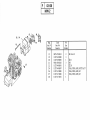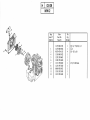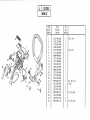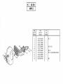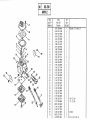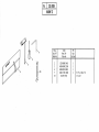
1
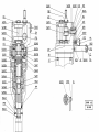
ANGLAIS
MIW.2
PORTABLE MOTOR
IMPACT WRENCH
Type
MIW.2
GEISMAR, the quality choice !
You have just acquired a machine for laying and servicing railway lines. We thank you for choosing equipment developed and constructed by
GEISMAR / STUMEC, the fruit of over eighty years’ experience.
Every day since 1924, the GEISMAR Group has been investing in research and state-of-the-art construction to offer you the quality and
reliability so essential to the requirements of the world of railways.
This machine, built entirely in France from design through to delivery, has been subjected to continuous, extremely strict controls. Formed of
different mechanical elements assembled by highly qualified fitters, your machine has been tested, calibrated and controlled at every stage of its
production.
We are convinced that it will give you every satisfaction and are, of course, at your service to offer you any recommendations you may require
for its use or its maintenance.
We thank you for the confidence you have shown in us and, in the hope that we will remain one of your privileged partners, we would like to
confirm that we are totally available for any comments or recommendations you may care to make.
In accordance with our environmental safety policy, this manual has been printed on recycled paper.
INT_Gb_00002_070525.doc
CONTENTS
CHAPTER 1 – SAFETY
1.1
1.2
1.3
1.4
CHAPTER 5 – SERVICING / MAINTENANCE
Forward
Safety instructions and general operation
General safety instructions
Specific safety instructions
5.1
5.1.1
5.1.2
5.1.3
5.1.4
5.1.5
5.1.6
5.1.7
5.1.8
5.1.9
5.1.10
5.1.11
5.1.12
5.1.13
5.1.14
1.4.1 Risks that may arise when using "MIW2"-type portable impact
wrench
1.4.2 Individual protective equipment
1.4.3 Fuel handling
1.4.4 Transport - Handling
1.4.5 Work
1.4.6 Safety pictograms and recommendations
CHAPTER 2 – DESCRIPTION OF THE MACHINE
2.1
2.2
2.3
2.4
General points
Overview
Technical data
Location of the machine in the railway gauge
CHAPTER 3 – INSTALLATION – STARTING
3.1
3.2
3.3
5.2
6.1
Optional equipment
6.1.1
Adaptable accessories
CHAPTER 7 – CATALOGUE OF SPARE PARTS
Inspecting the machine
7.1
Conditions of use
Operating
Storage
4.3.1
4.3.2
Preventive maintenance schedule
List of normally wearing parts
CHAPTER 6 – ACCESSORIES AND OPTIONS
CHAPTER 4 - USE
4.1
4.2
4.3
List of equipment and accessories essential for maintenance
Cleaning
Tightening
Carburettor
Muffler spark-arrester
Spark plug
Reducer and shock absorber
Dismantling the shock mechanism
Replacing the starting cable
Return spring strain
Replacing a return spring
Filter system
Intake strainer
Cooling system
Maintenance
5.2.1
5.2.2
Installing the socket
Fuel
3.2.1 Preparing the mix
3.2.2 Filling with fuel
Servicing
General storage recommendations
Specific storage recommendations
MIW2_Gb_00485_090407.doc
Drawings and parts lists
CHAPTER 1 – SAFETY
1.1 Foreword
The following set of rules has been drawn up to ensure the application of precautionary principles that help to preserve the safety of persons and property
when the machine is in use. Any failure to comply with these rules can have serious repercussions (bodily injury, etc.), and can even be fatal, so we must draw
your attention to the fact that all persons involved in the use, maintenance, storage or custody of the machine covered by the present manual must be familiar
with these rules.
Any users who cause an accident through failure to comply with these rules will be held personally responsible for the results of their actions.
1.2 Instructions for safety and general use
All persons using, servicing or repairing this equipment must have undergone the training, possess the skills, and have at their disposal the tools necessary to
carry out any such operations.
Before using the equipment, even in a maintenance context, it is necessary to read the corresponding instruction manual, together with its appendices, and the
safety rules in force in the workplace.
Comply carefully with the general safety instructions drawn up for the site by the person in charge of the site, especially if the work is carried out without
stopping or diverting traffic.
The equipment can only be used, serviced or repaired by competent personnel who have undergone thorough specialized training beforehand. The technical
documentation and the instructions are useful in completing the knowledge acquired during the training courses, but they can in no way replace theoretical and
practical qualifying training, provided in accordance with good professional practice.
If the operating company is not in a position to carry out the necessary training for its staff, at a satisfactory level, the GEISMAR/STUMEC Company is able
to provide advice concerning the training programme to be implemented.
The training must include an explanation of the various equipment functions, the instructions for use and maintenance, and the safety rules applicable, together
with practical exercises.
IMPORTANT! All persons using the machine must comply with the labour regulations in force
The GEISMAR/STUMEC Company cannot be held responsible for any modifications made without its
written approval, or for any assembly work not in conformity with its recommendations, especially in the
case of use of parts other than original manufacturer’s parts.
1.1
SECT_Gb_00003_070426.doc
1.2
1.3 General safety instructions
• The operator and the working environment
To avoid all risks of accident or injury, it is essential to wear:
- Sturdy, non-flammable clothing that is suitably close-fitting
- Strong, non-slip gloves
- Safety shoes
- Protective eyewear
- Safety helmet
- All other equipment necessary on the site or when using the machine
In the case of use of ear defenders, the safety instructions in force on the site must be complied with at all times.
Make sure that the machine vibrations do not lead to a loss of sensitivity in the hands. Adapt the working periods to the level of vibration caused by
the machine, which is shown within the framework of normal use.
Do not work with the machine if you are not sure that you can control it correctly. Do not start working with the machine until you are sure that you
can do so in full safety, for yourself (good conditions of visibility and lighting) and for other people (work calmly and carefully). Take care to ensure
you have a firm, stable footing; all unstable working positions must be prohibited.
The user must be in a physical and mental condition enabling work to be carried out without danger.
The work area must be free of all obstacles. The work area (and the surrounding areas) must be free of all flammable substances.
If anything does not seem clear to you, whether it concerns the machine or the work to be carried out, ask a qualified person for information. Do not
base your work on assumptions.
For underground use (tunnel or gallery), or in a closed area, make sure there is sufficient ventilation or extraction to avoid the risks generated by
inhaling exhaust gases or by their build-up.
This equipment must not be used in an explosive atmosphere.
Avoid working positions in which exhaust gases could come into contact with parts of the body, whether protected or not.
In a general way, take all necessary precautions to prevent flammable products from coming into contact with fire hazards.
The operator must ensure that no one else is within the working area. In particular, it is necessary to make sure that in the direction in which the
machine is travelling, no one can be hit. If someone is nonetheless in the path of the machine, the operator must stop and warn the person of his
passage.
When the machine is installed on the track, it must be handled only by the number of operators strictly necessary for its normal use.
As the overall size of the machines does not enable extinguishers to be carried on them, we strongly recommend placing extinguishers of an
appropriate type to deal with the fire hazards close to the machine.
The user must comply with all the regulatory environmental instructions applicable to the machine in use.
1.3
SECT_Gb_00004_090619.doc
1.3
• The operator and the machine
Before putting the machine into service each time, check that its condition and its operation are in compliance with the instructions.
In particular, make sure that the controls are free and in good working order, and that they are in the “stop” or “neutral” position. Never make any
modifications that could affect correct operation of the control systems.
All the protective elements must be kept carefully in place and in good condition.
Always keep the machine clean and remove any accumulated dust, especially if it could absorb flammable products.
Always move forwards when working.
When working, always hold the machine with both hands to ensure control at all times, and to be able to use it in full safety.
Never bring a machine close to a flame or a source of heat.
The machine must never be positioned close to hot or protruding elements that could damage some parts (tanks, exhaust, housings...).
Never move away from a machine while the engine is running, even when it is idling. Stop the engine immediately if the machine is not in use. After
stopping the engine, wait until all moving parts have come to a complete stop.
Work on the electrical installations on the machine can only be carried out by suitably qualified persons.
Read and make sure you fully understand all the signs placed on the machine, and always comply with all the instructions.
The signs placed on the machine include pictograms, manufacturer’s plates, and instruction labels. Make sure they are kept clean and replaced if
they have been damaged, or if they are missing or illegible. If one of these elements is on a part that is to be replaced, a new element must be present
on the replacement part. Please contact us on this subject.
THE MACHINE MUST NEVER BE USED FOR A PURPOSE OTHER THAN THAT FOR WHICH IT IS INTENDED
NEVER TOUCH A MOVING PART WITH A TOOL, OR WITH THE HAND, OR WITH ANY OTHER PART OF THE BODY
IT IS ESSENTIAL TO STOP THE ENGINE AND SET THE CONTROL TO THE STOP POSITION BEFORE CARRYING OUT :
1.3
ANY HANDLING WORK
ANY WORK TO CHANGE TOOLS OR SOCKETS
ANY WORK INVOLVING FUEL OR OIL (FILLING, TOPPING UP, CHECKING LEVELS, ETC.)
ANY REPAIR, MAINTENANCE OR CLEANING WORK
SECT_Gb_00005_080124.doc
1.3
• Using and handling fuel and oil
It is essential to stop the engine and set the control to the stop position before carrying out any work involving fuel (filling up, checking
the level, draining, etc.).
Always keep suitable extinguishers ready for use in all areas where fuel is handled (storage, filling up, etc.).
Always store fuel and oil in separate cans specially designed for the purpose and bearing the labels required by regulations. They must be stored in a
safe place, well away from all types of fire hazard.
Each time a machine is started up, and while it is running, make sure that there are no fuel leaks from any part of the machine. If a leak is suspected,
stop the engine immediately and do not restart the machine until the leak has been repaired.
Never carry out any work on a fuel tank or handle fuel to fill a tank, or for any other reason, in an area where there could be a fire hazard (such as a
burning cigarette, a blowtorch, sparks, etc.) or substances that are incandescent or at a high temperature (such as welding spatters, slag, clinker, etc.).
All such work must always be carried out outdoors or in a well-ventilated area.
Always turn all mobile phones off while filling a tank with fuel or handling fuel.
Carefully tighten the fuel filler cap each time, and check that no fuel leaks from it.
Always remove a filler cap slowly, to enable any internal pressure to be released without spraying any fuel out. Take special care if the surrounding
temperature is high.
When putting fuel in a machine that has heated up, never fill the tank completely. Do not put in more than three-quarters of the tank capacity.
If fuel starts to boil in the tank when putting fuel in a machine that has heated up, screw the cap on again immediately and leave the machine to cool
down.
Make sure the fuel used is suitable for the type of engine on the machine. See the user manual for the engine.
Do not inhale fuel vapour.
If it is necessary to drain the fuel tank, pour the fuel into a container designed for the purpose and bearing the labels required by regulations. Always
close them tightly, even if they only contain a small quantity. Never use a glass container.
Never use fuel for cleaning work. Use only non-flammable, non-toxic products that are harmless for the user, the equipment and environment.
If fuel has been spilt near the filling area for any reason, clean it up immediately. Clean straightaway any spillage of fuel on the skin. Make sure no
fuel has been spilt on your clothes; otherwise, change clothes immediately. Remove all rags or other materials used to wipe fuel, and store them in a
safe place well away from all sources of heat or combustion. Move the machine well clear of any spilt fuel before starting it up (at least 6 metres
away), and do not move any closer to the area while the engine is running.
IN CERTAIN CASES HANDLING OIL CAN GIVE RISE TO THE SAME TYPE OF RISKS AS HANDLING FUEL. IT IS THEN ESSENTIAL TO TAKE THE
SAME PRECAUTIONS WITH OIL AS THOSE SET OUT ABOVE FOR FUEL.
1.3
SECT_Gb_00006_090619.doc
1.3
•
Tools to be used on the machine
Use only the types of tools intended for normal use of the machine.
Measure the speed of all rotating tools at regular intervals.
Never use tools at speeds greater than the maximum speed for which they have been designed and approved.
Never use damaged tools or tools that have reached their maximum level of wear.
•
The engine on the machine
Never touch the hot parts of the engine, and especially the exhaust pipe. If it is necessary to work on the engine, wait until it has cooled down.
Check the engine rotation speed at regular intervals, and especially after fitting tools or reassembling the machine. Adjust if necessary.
Never exceed the speed shown in the technical specifications.
After starting with the choke, remember to return the choke to the normal running position.
Never wind the starter rope around your hand, and never release it suddenly.
If the machine does not operate correctly after the engine has been started, stop the engine and inform the head of maintenance.
•
For petrol engines, use only spark plugs whose tops are as shown in drawing 1 opposite. If the plug is fitted with a
screw top, make sure the top is fully tightened. After fitting the spark plug, make sure that the plug cap is in good
condition and that it stays firmly on the plug. Carefully check the fastening system to make sure that no sparks can
be formed.
Using trolleys (If applicable)
A machine designed to work on a trolley must not be used without the trolley. The trolley is thus an integral part of the machine. The machine and
the trolley must not be used separately.
Trolleys whose use is dedicated to a machine must never be used to transport equipment or personnel, or attached to a vehicle.
Before fitting the machine on its trolley, it must be placed correctly on the track to ensure that it can run freely. If it is on a sloping section of
track, make sure the trolley is kept immobile while the machine is being put on the track or taken off it.
Attention, the trolley takes up the full width of the track and can cause injuries to the legs if it hits someone.
1.3
SECT_Gb_00007_090617.doc
1.3
1.4
Specific safety instructions
1.4.1 Risks that may arise when using "MIW2"-type portable
impact wrench
The main danger that these machines may cause for the user and those
around him are:
Fire connected with fuel handling.
Injury through incorrect socket attachment.
Loose clothing becoming caught up in the sockets.
Injury caused due to not keeping the machine in good working order.
•
•
•
•
When changing sockets or accessories, never replace the pins with
nails, iron wire, etc..., which might snag on and drag clothing? Always
carefully put the dowel pin and spring retaining ring back in place.
There are no control or handling parts located near the exhaust, so
there is no risk of burns when used correctly. Nonetheless, in the event
of special use, wait for the exhaust to cool down.
While working, always hold the machine firmly with both hands.
Carry out handling operations carefully and only when the engine is
off. Be aware of the weight of the machine so that you can use the
most appropriate action, in order to guaranty that all handling
operations are carried out safely, and especially if it is difficult to
access the worksite.
1.4.2 Individual protective equipment
• All personnel using this equipment must wear the
clothing listed in paragraph §1.3 "General safety
instructions / The operator and his environment".
• He must wear a helmet and safety boots with non-slip
soles and steel toes.
• Use of protection to avoid inhaling the exhaust fumes is
also recommended.
1.4
• Use of auditory protection is also recommended
(nonetheless, be sure to follow the applicable railway
worksite regulation carefully in order to determine if
this can be used or not).
1.4.3 Fuel handling
• Clean around the filler hole to prevent impurities from entering the tank
or damaging the priming plug sealing joint.
• Carefully open the fuel tank plug so that any excess internal pressure
can escape slowly, without ejecting fuel.
• Never open the bayonet lock plug with a tool. You may damage the plug
and fuel may escape.
• Only use unleaded petrol with octane number at, at least, 90 RON.
GASOHOL, METHANOL, ETHANOL and ALCOHOL are
FORBIDDEN. Using these products increases the risk of fire or
explosion, and may cause serious, even fatal, injury to the user or those
around him.
• As petrol is highly inflammable, make sure the machine is at least 6m
from the filling site when starting it.
• Use a petrol-oil mix in the exact dose recommended in § 3.2.1
"Preparing the mix", in order to minimise the carbon deposits that may
cause sparks in the exhaust.
• Regularly check that the fuel tank plug is properly sealed. Check the
state of the O-ring on the filling plug. Replace it immediately if drops of
petrol form.
MIW2_Gb_00486_090407.doc
1.4
1.4.4 Transport - Handling
• Never transport the machine with the engine running, even on idle.
• Only carry the machine using the tubular handle, with the shock
mechanism pointing backwards.
• When transporting it in a vehicle, carefully fasten the machine to
immobilise it.
1.4.5 Work
• The machine must only be used by a single authorised operator.
• The machine must be used IN THE AXIS OF SCREWING.
• If the work takes place on a double track, pay particular attention to
activity on the track that is free to traffic. In all cases, use of the impact
spanner must respect the railway recommendations applicable where the
machine is being used.
• This machine was designed and manufactured solely for screwing
and unscrewing splice plate bolts and rail fastenings. Any use other
than that described in this manual will be considered «non-compliant"
and will free the manufacturer of all responsibility; the user will be
entirely and solely responsible.
"Compliant use" presumes observation of the recommendations for use
and maintenance of the machine stated in this manual. All
recommendations for work accident prevention described herein must
also be respected, while fully respecting the general applicable
legislation governing safety and worksite health.
• Prior to operating, make sure it is in good working condition. Never
modify the machine.
• Do not use ether or other similar products to assist in starting the engine.
• Do not work with the throttle device pushed in; it must only be used for
starting.
• Stop the engine before undertaking any maintenance and repair
operation. If the engine must operate (adjustment of the carburettor and
check of the maximum light speed), make sure that the work space has
lots of fresh air or is well ventilated.
• Never use a portable power bolter if the muffler is defective (risks of
fire and hearing problems).
• As soon as the engine is running, it emits toxic exhaust
gases. These gases can be odourless and invisible.
Never work with the machine in closed or poorlyventilated premises. When working in trenches,
depressions or restricted areas always make sure there
is sufficient ventilation. Danger of intoxication.
• Perfect adjustment of the engine idle is especially important so that the
socket does not turn when the throttle trigger is at rest (refer to §5.1.4
"Carburettor" if an adjustment is necessary). NOTE: when the throttle
trigger is released, the socket turns freely for a moment.
• If compressed air is being used for cleaning, wear protective clothing
and a mask or goggles. The air pressure at the nozzle tip should be less
than 2 bars.
1.4.6 Safety pictograms and recommendations
The safety pictograms and recommendations must be present on the impact
spanner at the indicated location.
If one of them is missing or has deteriorated, another must be ordered
immediately and installed in its place.
If a component bearing a label has been replaced, make sure a new label is
placed on the replacement part.
Reference: N° 75022 (yellow)
Emplacement: stuck on the
cowling to the top of the stopper of
filling.
Reference: N° 12528 (yellow)
Emplacement: stuck on the
cowling beside the handle of
launcher.
1.4
MIW2_Gb_00487_090407.doc
1.4
CHAPTER 2 – DESCRIPTION OF THE MACHINE
2.1 General points
Manufacturer:
The "MIW2" is also unique in having efficient protection against flying
ballast.
GEISMAR / STUMEC
Route d’Italie
The "MIW2" has two handles for safe and easy handling both horizontally
and vertically.
38110 LA TOUR DU PIN
The "MIW2" has a standard 1" (1 inch = 25.4mm) drive chuck.
FRANCE
Description of the
equipment:
Portable impact wrench
Type:
MIW 2
Lubrication is by oil bath, bringing a number of advantages:
- More even lubrication than with grease, which doesn't provide even
lubrication of active areas of the mechanism.
- Good heat dissipation and dampening of the sound produced by the
shock mechanism.
The "MIW2" model portable power bolter is designed to screw and
unscrew sleeper screws, fish plate bolts and nuts. This machine is the most
powerful on the market, so the most tightly screwed in components can be
unscrewed on railway tracks.
Filling and draining is through a magnetic plug that removes all metal
particles from the oil.
For increased operator comfort, the power bolter can be used with support
cart (optional).
Light and compact, it can be carried and handled easily by a single
operator. The comfort of use, low vibration despite the high power and its
durability make this machine the ideal tool for use on railway worksites.
The "MIW2" model portable power bolter works with a two-stroke aircooled engine, centrifugal clutch and diaphragm carburettor and electronic
starter.
Depending on the use it can be used horizontally for fish plate bolts and
nuts or vertically for sleeper screws.
The MIW2 was developed in an exclusive partnership between GEISMAR
STUMEC and STIHL. It is therefore the only portable power bolter to have
a STIHL engine.
2.1
MIW2_Gb_00488_090407.doc
2.1
2.2 Overview
B
C
D
A
E
F
K
L
G
H
J
M
N
Ref.
Description
A
Rear hand guard
B
Rear handle
C
Air filter cover
D
Front tube handle
E
Muffler with protective screen
F
1” (25.4mm) drive chuck
G
Shock device
H
Rotary speed reducer
J
Oil filling/draining plug
K
Oil level indicator
L
Front handle
M
Reversing lever
N
Air filter cover lock
P
Accelerator trigger lock
Q
Starting cable handle
R
Fuel tank plug
S
Start/stop universal lever
T
Accelerator trigger
P
Q
2.2
R
MIW2_Gb_00489_090407.doc
S
T
2.2
2.3 Technical data
Machine dimensions
Engine
Length / width / height……………….….................
mm
650/430/270
Weights
Type……………………………………………. ………..
STIHL MS 290
Displacement…………………………………...
cm³
56.5
Machine (empty) ……………………....……….......
kg
19
Power (at 9000 rpm)……………………............
kW
3
Machine (in operating condition).......………….......
kg
20,3
Cylinder bore……………………………...........
mm
46
Cart (optional)………………………………...........
kg
17.5
Max speed *...………………………….….........
rpm
12000
Piston stroke………………………………........
mm
34
………..
Membrane type carburettor
Noise **
...............
dB (A)
102 (±2)
Carburettor………………………………..…....
…….........................
dB (A)
117 (±2)
Work cycle………………………....................... ………..
2 stroke at air flow
Cooling……………………….………............... ………..
Air
Acoustic pressure level (cutting) (Laeq)
Acoustic power level (Lwa)
(2)
(1)
Vibrations *
Vibration level (au ralenti) (Aeq) (3)..........................
ms
-2
5,8 (±2%)
Vibration level (en frappe) (Aeq) (3)..........................
ms -2
13 (±2%)
Estimated vibration level for 1 hr use over one 8 hr
day (Aeq) (3).............................................................
ms -2
4,6 (±2%)
Machine
Idle adjustment speed *………………….................
rpm
2800
Tightening torque…….…………................…..........
N.m
1850
Loosening torque…………………...........................
N.m
2000
Socket at maximum engine speed..............................
rpm
1350
………..
Electronically controlled
magnetic hand wheel
Spark plug (shielded)…………………………... ………..
Bosch WSR 6,
or NGK BPMR 7 A
Electrode separation 0.5
Ignition………………………………………....
Fuel tank capacity……………...........................
litre
Fuel (variable mix depending on oil used 1 :25
or 1 :50)....……………......................................
………..
Starting system…..…………………….............
………..
0.560
Mix (oil – unleaded petrol)
Automatic return starting
cable
Cable Ø 3.5mm, 960mm long
* These values are average values for a machine in good condition and can change from one machine to another.
(1)
Measurements done according to NF EN ISO 11204 while machine working. (2) Measurements done according to NF EN ISO 3746 while machine working. (3) Measurements done according to NF EN ISO 5349 while machine working.
2.3
MIW2_Gb_00490_090831.doc
2.3
2.4 Location of the machine in the loading gauge
The diagram below shows the dimensions of the machine in relation to the low loading gauge UIC 505-1 (track with nominal displacement of 1435).
575
105
765
280
2.4
MIW2_Gb_00491_090407.doc
2.4
CHAPTER 3 – INSTALLATION – STARTING
3.1 Installing the socket
All socket mounting and dismantling operations must take place with the engine off.
When changing a socket, never replace the dowel pin by a protruding object (nail, wire,
etc…), which may snag on and drag the operator's clothing, even cause injury. Always
carefully put the dowel pin and spring retaining ring back in place.
3
To install the socket, proceed as follows:
2
- Partially insert the spring retaining ring Ref.② in the socket slot Ref.①, to
leave one of the two holes free for the pin Ref.④.
- Fit the socket Ref.① in the drive chuck Ref.③.
- Match up the sockethole Ref.① and the drive chuck hole Ref.③, then insert
the dowel pin Ref.④.
- Then release the spring ring Ref.②.
• The output shaft has a 1" (25.4 mm) drive chuck (Ref. 56036). Use special bushes for impact
wrenches (Size 32 to 42), with a 1" drive chuck and pin attachment (Ref. 56043) and spring
retaining ring (Ref. FPR).
1
4
Fitting a reduction bush decreases the machine's efficiency.
3.2 Fuel
3.2.1 Preparing the mix
The two-stroke engine of the impact spanner must be powered by a mix of petrol and engine oil. The quality of these components and the mix ratio have a
significant impact on the operation and the durability of the engine.
•
Fuel Only use unleaded petrol with at least 90 RON.
GASOHOL, METHANOL, ETHANOL and ALCOHOL are FORBIDDEN.
3.1
MIW2_Gb_00492_090407.doc
3.2
• Engine oil only use good quality oil for an air-cooled two-stroke engine. Preferably STIHL oil for two-stroke engines. It has been specifically developed
for STIHL engines and guarantees extended engine durability. Do not use either oil for water-cooled engines or oil for four-stroke engines.
• Preparing the mix always prepare the mix in a clean and certified container for the fuel.
➊ start by pouring half the petrol to be mixed
➋ pour in all of the oil.
➌ mix the two by shaking the container.
➍ finally pour in the rest of the petrol.
➎ carefully mix them again before filling the tank.
Petrol
Mix ratio:
- STIHL oil for two-stroke engines
1:50 = 1 volume oil + 50 volumes of petrol.
- other good quality oil for two-stroke engine
1:25 = 1 volume oil + 25 volumes of petrol.
+
1
5
10
15
20
25
STIHL twostroke oil
1:50 (2%)
0.02
0.10
0.20
0.30
0.40
0.50
Other quality
two-stroke oil
1:25 (4%)
0.04
0.20
0.40
0.60
0.80
1.00
Units = litres
Storing the mix the mix with unleaded petrol is not stable very long. Therefore do not prepare it ahead of time but as you need it.
1
3.2.2 Filling up with fuel
Before filling up, shake the mix can vigorously.
There may be pressure in the can.
Open it carefully.
Before filling up, carefully clean the plug and the area around it so no impurity enters the
tank.
Position the machine vertically, so the tank plug Ref.① is pointing up.
Never completely fill the tank, but only put in a quantity of fuel equal to ¾ of the
maximum capacity.
Never fill the tank with the engine running
3.2
MIW2_Gb_00493_090407.doc
3.2
• Opening the plug:
➊ By hand, raise the pull-down clip to a vertical position (Fig.1).
➋ Turn the plug at the base counter clockwise (approx. ¼ turn) (Fig.2).
➌ Remove the tank plug.
Carefully open the fuel tank plug so that any excess internal pressure can
escape slowly, without ejecting fuel.
Never open the plug using a tool. You may damage the plug and fuel may
escape.
Fig.1
Fig.2
• Fill the tank in a well-ventilated area and never near possible sources of fire, such
as: blow torches, sparks, soldering equipment.
When filling, do not spill the fuel and never completely fill the tank. Never
completely fill the tank, but only put in a quantity of fuel equal to ¾ of the
maximum capacity.
• Closing the plug:
Fig.3
Fig.4
➊ Place the tank plug with the pull-down clip vertical; the marks should line up.
(Fig.3)
➋ Turn the plug clockwise (approx. ¼ turn) (Fig.4).
➌ Fold the pull-down clip down so it is flush with the surface of the plug.
If the pull-down clip is not perfectly flush with the surface of the plug and the clip lug
does not fit in the recess (arrow) of the filling spout, the plug is not correctly fitted,
and you must repeat the operation above.
3.3 Inspecting the machine
Prior to each use, in order to reveal any defects, a visual check must be carried out by a skilled and authorised person.
The inspection is mainly a visual and operational check.
The inspection phase ensures the different components are in good condition and have not been damaged during transport or storage.
• Checking protective housings and mould assemblies (this inspection takes place with the engine off)
- Visually check that there are no external defects, deformations, superficial cracks, wear or marks of corrosion.
3.2
MIW2_Gb_00494_090407.doc
3.3
• Checking the fuel level (this inspection takes place with the engine off)
- Check the fuel level and if necessary top it up ( : refer to §1.3 "General safety instructions" / "Use and handling of fuel" and 3.2.2 "Filling with fuel").
• Checking the operation (these inspections take place with the engine off)
- Check the throttle trigger, the throttle trigger lock and combined lever are working properly. These devices must move freely and never be modified.
- Check that the socket turns freely with no load.
• Checking the safety devices
- Make sure that the handles are clean and dry.
- Turn the engine on ( : refer to §4.2 "Operating") and make sure that it stops when the combined lever is moved to position "0".
- Make sure that the socket does not turn when the throttle trigger is at rest (refer to §5.1.4 "Carburettor" if adjustment is necessary).
• Miscellaneous checks
- Check the absence of oil leaks, and that the all fixing bolts are tight.
IN THE EVENT AN ANOMALY SHOULD BE FOUND DURING THIS INSPECTION OR DURING USE, THE MACHINE MUST BE RESTORED TO
FULL COMPLIANCE BY SKILLED PERSONNEL OR BY THE MANUFACTURER PRIOR TO RE-USE.
CHAPTER 4 – USE
4.1 Conditions of use
Work area and operator position
The operator's work area is between the two rails on a single string. The
operator must be within this zone to carry out all bolting and sleeper
screwing (inside and outside the rail).
If some work requires leaving this zone, make sure of the safety
conditions, especially if the work takes place without halting the
traffic on adjacent track.
3.3
MIW2_Gb_00495_090407.doc
WORK AREA
4.1
4.2 Operating
Positions of the universal lever
0 = Engine stopped – off.
= Normal operating position – the engine turns or can start.
To move the universal lever from position to
or
, simultaneously push in the throttle trigger lock and the throttle trigger.
= Hot start – position for starting the hot engine – activating the throttle trigger, the universal lever moves to normal working
position.
= Cold start – position for starting of the cold engine.
Starting:
➊ Simultaneously push in the throttle trigger lock Ref.① and the throttle
trigger Ref.②. While holding the two triggers in, push the universal
lever Ref.③ to position
. Then successively release the throttle
trigger, the universal lever and the throttle trigger lock Ref.①.
➋ Set the universal lever Ref.③ to air temperature and engine
temperature:
- if the engine is cold, set the universal lever to
(starting cold).
- if the engine is hot (also if the engine has already been running but is
still cold or if the very hot engine was turned off for less than 5min), set
the universal lever to
(starting hot).
3
3
6
4
5
1
2
➌ In order to make it easier to start the engine and to avoid risks of
accident, the lower part of the power bolter should be on the ground.
4.2
Place your foot on the rear hand guard Ref.⑤. Grasp the front handle
Ref.④ of the power bolter firmly with one hand. With the other hand,
slowly pull the starting handle Ref.⑥ vertically upwards, until you feel
compression, then pull it abruptly. Do not pull the cable fully out. Do not
release the handle and let it return abruptly back, but guide it back with
your hand in the opposite direction to the traction so that the cable winds
back up properly. Never wind the starting cable around your hand.
➍ After the first ignition, set the universal lever Ref.③ to
and
continue to start the engine. Once the engine is turning, push the throttle
trigger Ref.② slightly so the universal lever Ref.③ moves
automatically to normal operating position , and the engine idles.
Slowly rev the engine to warm it up.
Let the engine run on idle for 30 seconds prior to use.
MIW2_Gb_00496_090407.doc
4.2
Engine stopped:
Move the universal lever to the stop position 0.
If the engine doesn't start:
It may be that after the first starting kick, the starting lever Ref.③ did
not return to position
in time.
The engine is therefore flooded.
If the tank was filled after running empty:
➊ Adjust the position of the starting lever Ref.④ depending on the air
temperature and above all the engine temperature.
➋ Restart the engine.
➊ Place the starter damper lever in position
= starting hot (even
if the engine is cold).
➋ Pull the starting handle 10 to 20 times in order to ventilate the
combustion chamber.
➌ Restart the engine.
Make sure there is fuel in the tank.
Positions of the reversing lever:
Reversing lever to the right
Screwing
Reversing lever in the middle
Neutral.
Reversing lever to the left
Loosening
3
Never screw or unscrew while the engine is not hot.
Screwing operation:
2
Move the reversing lever Ref.① to the tightening position (to the right).
Place the machine in position on the bolt or sleeper screw while holding it firmly with both
hands: one hand holding the handle Ref.② with the throttle control handle and the other the
front tube handle Ref.③ (use in vertical position).
1
Rev the engine. The socket starts to move. Actual tightening power is only obtained after 3
seconds turning, starting from the moment when the blocking position is reached.
The portable impact wrench is not designed to screw at a precise torque. An
excessive screwing may damage the coachscrew or the sleeper.
4.2
MIW2_Gb_00497_090407.doc
4.2
Loosening operation:
Move the reversing lever Ref.① to the loosening position (to the right).
Place the machine in position on the bolt or sleeper screw in the same way as for tightening,
but holding it firmly with one hand on the handle Ref.② with the throttle control and the other
on the tubular handle Ref.③, or the front handle Ref.④ (use in horizontal position).
Rev the engine. The socket starts the loosening movement after a few seconds.
If the component does not unscrew, never continue for more than 10 seconds straight:
reverse and try to "unstick" the bolt or sleeper screw by screwing it in for 3 seconds.
Then start loosening it again and if after 10 seconds it still won't unscrew, try other
means.
4
3
NOTE: If the reversing lever does not move into position easily, lightly rev the engine in order to slowly rotate the reverser gears.
Never reverse when the engine is revving
After each use, put the reversing lever to the neutral (centre), stop the engine by moving the universal lever to position 0. Place the machine in a horizontal
position.
4.2
MIW2_Gb_00498_090407.doc
4.2
Storage procedures
4.3 Storage
4.3.1 General storage recommendations
The state of the equipment when recommissioned after storage depends
on the way it was prepared and protected before storage:
- cleaning the equipment (when cleaning, protect the moving parts
with grease).
- technical inspections to check for anomalies
During periods where the equipment is not in use, it is indispensible to
store it properly in order to keep it in good working order. Poorly stored
equipment may deteriorate when reused. Il is also important for the
personnel responsible for storage operations to take great care during
storage, and to carefully follow the recommendations.
4.3.2
Storage protection system
If work should be halted for more than one week:
The choice of storage protection systems depends on 2 main factors:
- the length of time it will be stored
- the storage conditions: "unprotected" storage (exposure to bad
weather) and "protected" storage (building, closed hangar, open
hangar, canopy, etc.)
The equipment must only be stored after being run in. Measures must be
taken to provide easy access around the equipment so maintenance
operations can be carried out.
Specific storage recommendations
Empty the fuel tank in a container in a well-ventilated area and clean
it.
Eliminate the fuel in compliance with the regulations governing the
protection of the environment.
Rev the engine until the carburettor is completely empty, otherwise
the carburettor membranes may stick.
Thoroughly clean the machine; especially the cylinder vanes and the
air filter.
Storage premises
In general, premises for storing equipment should provide as good
protection as possible against:
- dust, exhaust emissions, humidity
- direct sunlight
- rapid temperature changes
4.3
MIW2_Gb_00499_090407.doc
4.3
CHAPTER 5 – SERVICING / MAINTENANCE
5.1 Servicing
This equipment may only be serviced and repaired by skilled personnel with a thorough knowledge in general mechanics.
Training and specific tooling are required for servicing and repairing this equipment correctly.
Before carrying out any servicing or repair operation, stop the engine (leave the control in the stop position) and wait for it to cool down. If the engine
must operate (adjustment of the carburettor and check of the maximum light speed), make sure that the workspace is well ventilated.
Safety in use of this machine relies largely on correct servicing.
Waste resulting from servicing and maintenance operations (fluids, filters, used cloths, etc.) must be processed in accordance with applicable regulations
governing environmental protection.
Any part that is worn, damaged or missing must be changed or repaired immediately, whenever there is a risk in terms of safety.
5.1.1 List of equipment and accessories required for servicing
The following tooling is required for carrying out all the servicing and maintenance operations correctly.
Work tooling (provided with the machine)
Flat-head screwdriver (Ref. 0000 890 2300)
Screwdriver T27x120x70 (Ref.0812 370 1000)
Spark plug spanner (Ref. 1129 890 3401)
13 x 23 open-ended spanner (Ref. GAW)
1 Ring (Ref. FPR) and 1 Pin (Ref. 56043)
Pocket with tools (Ref. 0000 891 0801)
Maintenance and servicing tooling (not provided with the machine)
Multiple slip joint pliers
Octagonal spanner
3, 4, 5 and 6 spanners
Torx wrench 27
This list of tooling does not exclude the need for normal necessary equipment such as: cloths, brushes, grease, etc.
5.1.2 Cleaning
Make sure that the machine is kept as clean as possible. Care in cleaning the machine will lead to longer service life and improved performance.
Clean the machine carefully with a clean cloth or an airgun, taking special care to remove all dirt that has accumulated on it, especially close to any moving
parts. As a precautionary measure, always wear gloves to avoid injury or burning of hands. Do not use fuel for cleaning operations. Only use noninflammable, non-toxic products that are inoffensive for both the operator and the machine.
5.1.3 Tightening
After a running-in period of about 1 hour, check the position and tightness of all accessible nuts and screws (this does not apply to the carburettor adjustment
screw).
5.1
MIW2_Gb_00500_090407.doc
5.1
5.1.4 Carburettor
When shipped from the factory, the carburettor is delivered with the optimal adjustment corresponding to the pressure and climate conditions of the factory.
Apart from standard maintenance during use, it is recommended that you carry out repairs or adjustments to the carburettor using the agents of the GEISMAR
/ STIHL sales or breakdown repair network.
From time to time check the maximum rotation speed under load of the engine (9300 rpm). The carburettor must be inspected prior to commissioning:
atmospheric conditions and altitude can significantly affect this adjustment.
To inspect or adjust the carburettor, the machine must be on a blocked work position in order to measure the engine's speed under load. (Never rev the engine
for more than 10 seconds. Wait 1 minute between 2 revs).
A rotation generation mechanism rotation speed that is too high may cause premature wearing of some components, and seriously affect the machine's
performance.
For this inspection, use an electronic revolution counter (Ref. HLN). If the engine speed exceeds 9300 rpm under load, carry out another adjustment:
Turn the carburettor adjustment screws very slightly and carefully; the slightest rotation has a significant impact on the engine.
Standard calibration:
➊ Stop the engine.
➋ Check the air filter (replace it if necessary refer to §5.1.11).
➌ Check the muffler spark-arrester (clean it or replace it if necessary refer to §5.1.5).
➍ Acting precisely:
H Turning counter clockwise, screw the fast idle adjustment screw until it reaches the stop (maximum ¾ turn).
L Turn the rich idle adjustment screw clockwise until it reaches the stop then go back ¼ turn.
Adjusting the idle:
If the engine stalls on idle:
LA Turn the idle adjustment stop screw clockwise, until the socket starts to grip then go back ¼ turn so the socket does not grip when the engine is on
idle.
If the socket is gripping on idle:
LA Turn the idle adjustment stop screw counter clockwise, until the socket stops, then ¼ turn in the same direction.
If after this adjustment the socket does not stop on idle, have the portable power bolter repaired by a specialised dealer.
5.1
MIW2_Gb_00501_090407.doc
5.1
If the idle is not regular, if the engine does not turn over satisfactorily:
The idle adjustment is too poor (in the case of lowered air temperature).
L Turn the rich adjustment screw counter clockwise, until the engine turns and revs at a maximum until it reaches the stop.
If it is not possible to increase the idle enough using the idle adjustment screw stop screw LA, if the engine stalls in the transition phase between partial
and idle load:
L Turn the rich idle adjustment screw approximately ¼ turn clockwise.
Correcting the carburettor adjustment for use at high altitude:
If the engine is not operating satisfactorily, a small correction of the adjustment may prove necessary.
➊ Check the standard adjustment.
➋ Warm up the engine.
➌ Adjust the idle correctly.
➍ Turn the fast idle adjustment screw H and the rich idle adjustment screw L clockwise (starving the mix).
A too poor adjustment risks causing engine trouble, after a lack of lubrication or overheating.
NB: all carburettor adjustments take place with the flathead screwdriver delivered with the machine service kit.
5.1.5 Muffler spark-arrester*
If the engine power decreases, check the muffler spark arrester.
Prior to this operation, wait for the engine to be completely cold.
1
1
3
2
➊ Loosen and unscrew the nuts Ref.①.
➋ Remove the cover Ref.②.
➌ Remove the spark-arrester Ref.③.
Clean the spark arrester if it has become fouled.
Replace the spark arrester if it is damaged or there are a lot of deposits.
Fit the spark arrester and the cover.
*only for equipped impact wrench (USA, CANADA and AUSTRALIA)
5.1
MIW2_Gb_00502_090407.doc
5.1
5.1.6 Spark plug
In the event of a lack of engine power, difficulty starting or if the idle is irregular, always first check the state of the spark plug.
➊ Place the universal lever in position 0.
➋ Turn button Ref.① above the rear handle to the left so that the slot is
vertical.
➌ Move the carburettor housing cover Ref.② to the rear.
Move the pre-filter Ref.③ upwards.
Remove the starting cable switch Ref.④.
1
2
3
4
➍ Unscrew the spark plug using the socket provided, and dry it with a clean cloth.
➎ Check the state of the spark plug:
0.5
- If the spark plug has become fouled, clean it using a fine bristle metal brush. Then check that the electrodes
are 0.5mm apart. Correct this if necessary.
- If the spark plug electrodes are well worn, replace it.
➏ Screw in the spark plug and make sure the starting cable switch is firmly in place, and replace the pieces you have
previously removed.
Always use only shielded spark plugs (Cf §2.4 "Technical characteristics"). Other spark plugs may damage the
piston/cylinder.
After cleaning the spark plug and prior to operating, remove the possible causes for the fouling of the spark plug:
- clogged air filter (Cf §5.1.11)
- poor adjustment of the carburettor (Cf §5.1.4)
- too much oil in the mix (Cf §3.2.1)
5.1
MIW2_Gb_00503_090407.doc
5.1
5.1.7 Reducer and shock absorber
Lubrication:
This is done by oil bath, which has several advantages:
- better lubrication compared to grease, which may spray onto active surfaces of the mechanism.
-good heat dissipation and dampening of the sound produced by the shock mechanism.
Filling and draining via the plug Ref.①.
Use only one Polyalkylene glycol-type synthetic oil for gears corresponding to the specification
ISO: 6743/0 (1981) category C.
For example:
TOTAL:
MOBIL:
SHELL:
BP:
ESSO:
CARTER SY 220
GARGOYLE 22
TIVELLA WA
ENERGOL SGR-XP 150
COMPRESSOR OIL LG 50
CAUTION - These oils are
non-miscible
and
incompatible with mineral
oils and certain synthetic
oils.
2
1
Check the oil using indicator Ref.② each day. With the machine vertical, the oil rises to the middle of the indicator, (approx 0.7 litre volume).
Change oil approx. every 40 operating hours. Change oil for new machine after 10 hours.
When changing oil, clean the magnetic plug Ref.① that keeps out the metal particles in the oil. The presence of some particles is normal. On the other hand,
if the plug is full of particles, we strongly recommend disassembly followed by a thorough examination of the mechanism.
Clean the magnetic plug every week to remove the metal particles that accumulate during the operation of the machine.
5.1
MIW2_Gb_00504_090407.doc
5.1
5.1.8 Dismantling the shock mechanism
CAUTION - At this moment, nothing is holding the balls in place Ref.⑧.
The shock absorber washer Ref.⑫ (Ref. 56141) is subject to strong
mechanical actions and should therefore be replaced after a while. To do
this the entire shock assembly must be disassembled.
Fig.3
7
Fig.4
6
Note: disassemble the machine in a clean area.
8
➊ Change oil
➋ Remove the 4 screws Ref.①.
➌ Remove the housing Ref.②.
1
➐ Loosen the vice; the driving hammer Ref.⑥ can be removed. Remove
the drive spring Ref.⑨.
9
2
Fig.1
Fig.2
3
➍ Remove
the
mechanism
assembly by pulling upwards
through the planet carrier
(fig.1).
4
➑ Remove the spring cup Ref.⑩ (fig.5) being careful no to lose the balls
Ref.⑪ (fig.6).
Fig.5
Fig.6
11
5
➎ Remove the drive tip Ref.③.
and the spring Ref.④ and the
bearing ring Ref.⑤ (fig.2).
10
12
➏ Place the mechanism in a vice equipped with padded jaws to avoid
damaging the mechanism, then screw in the driving hammer Ref.⑥ and
the planet carrier Ref.⑦ (fig.3) until the 2 balls Ref.⑧ can leave their
slots (fig.4).
5.1
6
➒ Replace the shock absorber washer Ref.⑫ and the shock mechanism by
reversing the disassembly procedure.
MIW2_Gb_00505_090407.doc
5.1
5.1.9 Replacing the starting cable
1
10
➊ Unscrew the screw Ref.① (fig.1).
Unstick the fan housing Ref.② from the crankshaft housing Ref.③ and remove it
from the side.
Fig.1
Fig.2
Fig.2
➋ Pull on the handle Ref.⑧ (Fig.3) and block the pulley by hand Ref.⑤. Completely
unwind the cable from the pulley Ref.⑩ in order to slacken the spring (Fig.2). If the
starting cable is broken, the spring will already be slack.
➌ Using an appropriate screwdriver or pliers, remove the spring staple Ref.④ (Fig.4).
➍ Carefully remove the pulley Ref.⑤ and the washer Ref.⑥.
3
➎ Remove the ratchet Ref.⑦.
1
5
2
5
Fig.3
Fig.3
➏ Using a screwdriver as a lever, remove the handle cap Ref.⑧.
4
Remove the bit of the cable still in the pulley and the handle. Make sure the bush is
not expelled from the handle.
5
6
8
Fig.4
Make a simple knot at one end of the new starting cable then thread the cable, from
top to bottom, through the handle Ref.⑧.
➐ Thread the starting cable from top to bottom, through the cable guiding bush Ref.⑨
(Fig.3).
Fit the cap on the handle Ref.⑧.
9
Pass the starting cable through the pulley Ref.⑤ and tie it off.
Moisten the cable pulley bore with non-resin oil.
7
Slide the pulley Ref.⑤ on the axis, and move it around a bit until the eyelet of the
return spring clicks into place (Fig.5).
5
6
➑ Replace the ratchet Ref.⑦ in the pulley.
➒ Slide the washer Ref.⑥ on the axis.
Push the spring staple Ref.④ in place on the axis and on the ratchet pilot point using a
screwdriver or appropriate pliers. The staple must be oriented clockwise, as shown in
the figure.
Fig.5
7
5.1
MIW2_Gb_00506_090407.doc
5.1
5.1.10 Return spring strain
➊ Make a loop with the unwound part of the starting cable and, with this loop, turn the pulley Ref.⑤ six
rotations in the direction of the arrow.
➋ Keep hold of the pulley.
➌ Pull the twisted cable outwards and untwist it.
➍ Release the pulley.
➎ Slowly release the starting cable, so it winds onto the pulley.
The handle of the starting cable must be firmly drawn into the cable-guiding bush. If it is hanging on
one side: retension the spring with an additional rotation.
With the cable completely out, the pulley must still be able to complete a half rotation. If this is not
possible, it means the spring is too tight – it may break.
5
➏ Remove one coil of the cable from the pulley.
➐ Replace the fan housing.
5.1.11 Replacing a return spring
➊ Dismantle the cable pulley by following operations n°1 to n°4 described in §5.1.8 "Replacing the
starting cable".
10
11
2
12
➋ Remove the spring by carefully levering it out with a screwdriver.
➌ Moisten the replacement spring with a few drops of non-resin oil.
➍ Position the new spring with the mounting cable in the fan housing Ref.②. Pass the spring eyelet
Ref.⑩ over the housing fin Ref.⑪.
➎ Use an appropriate tool (screwdriver, punch or such) on the stamps (arrows) and slide the spring
Ref.⑫ into the housing slot. The spring is then freed from the assembly frame.
If the spring comes free of the housing, fit it back into place by winding it counter clockwise, outside
to inside.
➏ Refit the pulley to the cable, tauten the return spring, refit the fan housing and tighten the screws.
NB: if the spring comes free of the casing, refit it by winding it counter clockwise, outside to inside.
5.1
MIW2_Gb_00507_090407.doc
5.1
5.1.12 Filter system
A clogged filtration system can cause the following problems:
- excessive fuel consumption
- problems starting the engine
- decreased engine power
- premature wear to the engine
At the end of each work day (See Fig.1):
➋ Turn button Ref.① above the rear handle to the left so that the slot is vertical.
Fig.1
➋ Push the carburettor housing cover to the rear.
1
➌ Roughly clean the area around the filter.
➍ Push the pre-filter Ref.② upwards (Fig.2).
➎ Unscrew the split nuts Ref.③.
➏ Remove the main filter Ref.④.
Separate the two filter parts.
Knock the filter or clean it with compressed air by blowing from inside to outside, being
careful to avoid damaging it.
Fig.2
2
4
3
If clogging continues:
Wash the filter parts in universal STIHL cleaning product or a clean and non-flammable
cleaning liquid (e.g. warm soapy water) then dry it.
Do not brush the felt filter!
Replace the damaged filters.
Fit the filter into place.
The filtering power and air permeability of all the components of the air filter of this power bolter are well-tuned.
For this reason, only use recommended air filters (referenced in § 5.2.2). The high quality of these parts and the recommended servicing and maintenance
operations guaranty smooth operation and long durability of the engine.
IMPORTANT: If other brand filters are used, even if there dimensions seem appropriate, optimum protection of the engine block against impurities is not
guaranteed. In the event of increased wear to engine block components or damage to the engine block resulting from the use of such filters, no warranty claim
will be accepted.
5.1
MIW2_Gb_00508_090407.doc
5.1
5.1.13 Intake strainer
The intake strainer is on the inside of the fuel tank and must be replaced in the event of clogging or at least
once per year.
➊ Drain the fuel tank.
➋ Remove the intake strainer Ref.① from the tank with a hook and pull it from the flexible hose.
➌ Place the new intake strainer in the flexible hose.
1
➍ Place the intake strainer in the fuel tank.
To avoid clogging on the intake strainer, protect the fuel tank from impurities while filling.
5.1.14 Cooling system
There is a cooling system to maintain the operating temperature of the portable power
bolter as low as possible therefore avoiding damage to the cylinder and piston.
To preserve its efficiency, this system must be cleaned once per week with compressed
air.
1
1
1
1
➊ Unscrew the four screws Ref.① (multiple spanner).
➋ Remove the fan cover Ref.②.
➌ Clean the fins and the inside of the fan cover, the fins on the rotor fan, the halfhousing, the inside of the air inlet cap and the cooling vanes on the cylinder.
➍ Tighten the four screws again Ref.①.
5.1
2
MIW2_Gb_00509_090407.doc
5.1
5.2 Maintenance
5.2.1 Preventive maintenance schedule
Control components
Accessible nuts and bolts
(except for adjustment screws)
If needed
In event of damage
In event of breakdown
Once per year
Once per month
Reference
X
Inspecting the machine
Entire machine
Once per week
TYPE OF OPERATION
After each use
COMPONENTS
Prior to each use
FREQUENCY
Perform general cleaning with a clean cloth or blow
nozzle to remove dirt from the machine
Chap.3 - § 3
X
Chap.5 - § 1.2
X
Check the operation
Chap.3 - § 3
X
Retighten
Check that the drive chuck does not turn on idle
X
Chap.5 - § 1.4
Carburettor
X
Adjust the settings
Muffler spark-arrester
(if equipped)
X
Clean
Chap.5 - § 1.5
X
Replace
X
Rectifying electrodes spacing
Chap.5 - § 1.6
Spark plug
X
Replace
5.2
Chap.5 - § 1.3
Magnetic plug
Clean
Drawn cup needle bearing
(Engine / Clutch)
Greasing
X
Chap.5 - § 1.7
X
MIW2_Gb_00510_090407.doc
X
X
Chap. 5- § 1.8
5.2
Shock device
Reference
If needed
In event of damage
In event of breakdown
Once per year
Once per month
Once per week
TYPE OF OPERATION
After each use
COMPONENTS
Prior to each use
FREQUENCY
X
Check the oil level
Chap.5 - § 1.7
X
Oil change
Starting cable
Replace
X
Chap.5 - § 1.9
Return spring
Replace
X
Chap.5 § 1.11
Shock absorber washer
Replace
X
X
X
X
X
X
X
X
Clean the filter casing and area around it
Chap.5 § 1.12
Filter system
Replace
X
Clean
Intake strainer
X
Replace
Cooling system
X
Clean
X
Check sealing
Chap.5 § 1.13
Chap.5 § 1.14
Chap.1 § 4.3
Fuel tank
X
Clean
Maximum speed IN LOAD of drive
chuck
Chap.5 §1.8
X
Check
Chap.1 § 4.5
NOTE: These recommendations are not limitative. Permanent checks on the machine and well-organised preventive maintenance will always extend the
machine’s service life.
Indications given on the preventive maintenance schedule are given for machines used under normal conditions. In more difficult working conditions and
longer working days the frequency of maintenance operations must be shortened accordingly.
5.2
MIW2_Gb_00511_090407.doc
5.2
5.2.2 List of normal wear parts (this list does not include engine parts)
This is a list of normal wear parts on the machine together with the conditions under which they should be replaced.
Nevertheless, any part that is worn, damaged or missing must be changed or repaired immediately, whenever there is a risk in terms of safety.
Description
Let.
No.
Drive tip
56036 B
1
Cam hammer
56046 A
1
G 10 x 17 x 3 sealing joint
FPE
1
BA 34 x 46 x 8 sealing joint
FPF
1
Friction washer
56028
1
Ø 17 x 28 x 7 sealing joint
FBE
1
Spark-arrester *
56151
1
Intake strainer
0000 350 3500
1
Air filter
1127 120 1620
1
Air filter
1127 120 1621
1
Bosch WSR 6 F spark plug
1110 400 7005
1
NGK BPMR7A spark plug
0000 400 7000
1
Lower protector
56148
1
Pre-filter
1127 124 1501
1
Ø 3.5 x 960 mm starting cable
1113 195 8200
1
Return spring
1129 190 0601
1
Starting handle
1121 195 3400
1
Spring ring
56042
1
Replacement conditions
Wear or breakage
Oil leak or poor operation
Clogging
Well-worn spark plug electrodes
Deterioration
Breakage
*only for equipped impact wrench (USA, CANADA and AUSTRALIA)
5.2
MIW2_Gb_00512_090407.doc
5.2
CHAPTER 6 – ACCESSORIES AND OPTIONS
6.1 Optional equipment
6.1.1
Adaptable accessories
Bushes with a different square coupler can be used by fitting a reduction
bush Ref.① (Ref. 56076) between the output shaft Ref.② and the
tightening bush Ref.③. Then use a ball spanner attachment device Ref.④
(Ref. 880E).
2
1
4
3
6.1
MIW2_Gb_00513_090407.doc
N.
Description
56000 D
25.4 – 23mm reduction bush assembly
56000 J
25.4 – 23mm reduction bush assembly for use with
ball attachment
56000AE
Extended bolter assembly adaptable to MIW2
6.1
CHAPTER 7 – SPARE PARTS CATALOG
7.1 Drawings and parts lists
7.1
CH7_Gb_00032_070529.doc
7.1
IMPORTANT
Afin que votre commande de pièces de rechange soit suivie d’une livraison prompte
et correcte, bien indiquer :
- Le rep., le nombre et la désignation des pièces de rechange
- Le type et le n° de série de la machine (plaque sur le châssis)
*********************************************************************
IMPORTANT
To ensure that you are delivered promptly and correctly after placing an order for
spare parts please state:
- the Reference, number and description of the spare parts
- the type and serial number of the machine (to locate this number, look at the plate on the chassis)
**********************************************************************
WICHTIG
Um uns eine schnelle und fehlerlose Erledigung lhres Ersatzteil-Auftrages zu erlauben,
bitten wir Sie um folgende Angaben :
- Seriennummer und Baujahr der maschine
- Benennung und Bestellnummer der Ersatzeile
CDE_Gb_00033_070529.doc