1
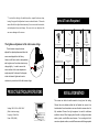
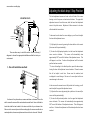
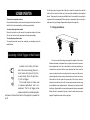
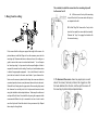
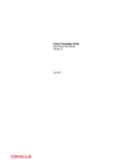
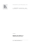
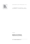
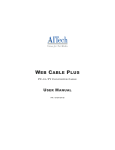
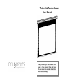
Tauten Tab Tension Screen User Manual Thank you for choosing a Tauten Series Tab Tension screen by Cirrus Screens. Please read through this user manual and understand all instructions before installing and using! LIMIT OF LIABILITY Cirrus Screens shall not be liable under any circumstances for any Warning 1. It is normal to see slight horizontal marks on the fabric after storage but they consequential, incidental, special or exemplary damages arising from, or in any connection with this agreement or the products, including but Notice will disappear gradually when the fabric has been unrolled for a short period. 2. It is also normal to see slight marks on both sides of the black border after not limited to lost profits, or any claim based on indemnity or storage but they will disappear gradually when the fabric has been unrolled contribution, or the failure of any limited or exclusive remedy to achieve for a short period. its essential purpose or otherwise. Purchaser's exclusive remedy, as against Cirrus Screens, shall be the repair or replacement of defective parts. If Cirrus Screens lists a product on its web site at a price or 3. Before installation of the projection screen on a wall or ceiling, make sure that it can afford the weight of the screen. 4. Dust, dirt and scratches on the projection surface will affect the picture specification in error, or that is no longer available for any reason, quality. For prevention, take notice of the points below: Cirrus Screens reserves the right to cancel the sale without incurring § Do not touch the projection surface with hands. any liability. § Do not write or draw on the projection surface. § Do not use fingers or sharp objects to point on the projection surface as Phone: 1-888-588-2164 Fax: 1-888-315-3469 [email protected] www.cirrusscreens.com this will damage the screen fabric. § Use a soft damp cloth to clean the projection surface only. § Do not use chemical cleaning agents or alcohol based cleaners. ENVIRONMENTAL CONDITIONS The recommended operating temperature is between 10C and 40C with humidity lower than 90%. fumes and/or moisture. Avoid installations in environments prone to gas Maintain a minimum 1 meter distance between the optional IR control box and any wireless or infrared signal with high frequency such as electric welding machines, medical equipment or any other electrical device. WARRANTY Misuse of the screen may cause damage to the screen itself or cause personal injury. • Warning Two (2) year parts and labor warranty from defects in workmanship from date of purchase. • Defective product is to be returned to dealer for any warranty service. To prevent damage to the screen and personal injury, ensure the • screen is mounted correctly and securely. Please do not return any defective items directly to Cirrus Screens, as they will be refused. • Missing Parts must be reported within 30 days of purchase. After 30 days, customer will be responsible for the cost of the parts and shipping & handling. Do not climb on or hang things from the screen. Doing so may • Warranty is non-transferable. damage the screen, detach the screen from the wall, or cause • Warranty applicable to purchases made through authorized dealers personal injury. only. Please contact Cirrus Screens for a list of authorized dealers. This warranty does not extend to any product that has been damaged Retract the projection surface back into the case after use. This will or rendered defective as per the following: protect it from dust and dirt, and prevent it from loosening. A. As a result of misuse, abuse or negligence. B. By the use of parts not manufactured or sold by Cirrus Screens. Do not disassemble the screen. Doing so may cause further damage C. By non-authorized modification of the product. to the screen and will void the warranty. If the screen needs repairing, D. As a result of service by anyone other than Cirrus Screens or Cirrus contact the dealer from whom the screen was purchased. Screens Authorized Service Provider. E. Improper transportation or packaging when returning product to a F. Cirrus Screens Dealer, or Authorized Service Provider. G. Improper installation of third-party products. H. Improper environment (including temperature or humidity). I. Unusual physical or electrical stress or interference, failure or fluctuation of electrical power, lightning strike, fire, or Natural Disasters. * To return this setting to the default position, repeat the above steps, turning the upper limit adjustment screw counterclockwise. Please be Parts & Tools Required aware this will not adjust instantaneously, the screen must be retracted, and re-deployed to reveal change. Be sure not to over adjust as this ① can cause damage to the screen. The tightness adjustment of the tab tension strings The tab tension strings have been X 2 pcs 12 VOLT Trigger wire X1 pcs User Manual Mounting Bracket ⑤ ③ ② X1 pc ⑥ ④ Wall Remote With connecting cable X1 pc ⑦ ⑧ adjusted for optimal performance before the screen was shipped from the factory. However, with factors such as transportation and long time use, the surface tension may change slightly. Hanging Bracket Screw 6x60mm (Depends on size) ⑨ In order to ensure the IR Remote X 1pc Allen Key Wand X1 pc RF Remote X 1pc ⑩ screen surface is flat, some adjustments maybe required. As shown in the diagram, rotate clockwise to tighten and counter clockwise to provide slack of the tab tension strings. PRODUCT ELECTRICAL SPECIFICATIONS RS232 Repeater X1 pc Central control cable X1 pc INSTALLATION METHOD The screen can either be wall mounted or hung from the ceiling. Choose the most suitable method that will enable the screen to be Voltage: 100V~120V or 220V~240V located where the entire audience can see the whole screen when it is (Refer to label on casing) fully extended. Ensure the right equipment is used for whichever Frequency: 50Hz~60Hz method is chosen. When hanging from the wall or ceiling into wooden Power: 150W (MAX) studs or joists, use ø6x60mm wood screws. For mounting into brick, concrete or plaster surfaces, use ø6x60mm screws with the appropriate screw anchors or wall plugs. Adjusting the black drop / Stop Position The limit adjustment screws are found on the left side of the screen MOUNTING CLIPS housing, next to the power cord and control interface. The upper limit Lifting nut adjustment screw is the white screw, while the lower limit adjustment screw is the yellow screw. Adjustment of these screws is to be done with standard slot screw driver. Screen house Installation hole 2 Installation hole 1 To decrease how far down the screen deploys, you will need to adjust the lower limit adjustment screw. Ring-pull 1) Fully deploy the screen by pressing the down button on the remote (the screen will stop automatically.) There are three ways to install the screen. Use the following 3 diagrams to choose the appropriate installation method that suits your environment. 2) To raise the fully deployed position, turn the lower limit adjustment screw counter clockwise. The screen will automatically raise approximately 5/8" for each full rotation of the adjustment screw. This will happen in real time. Continue this adjustment until the desired position has been reached. 1. On-wall installation method: * To return this setting to the default position, repeat the above steps, turning the lower limit adjustment screw clockwise. Please be aware this will not adjust in real time. Screen must be retracted, and re-deployed to reveal change. Be sure not to over adjust as this can cause damage to the screen. In the rare case the screen does not fully retract into its casing, you will need to adjust the upper limit adjustment screw. 1) Fully retract the screen by pressing the up button on the remote (the screen will stop automatically.) As shown in the picture above, measure and draw a reference line on the wall to ensure the screen will be centered and mounted level. Use a stud finder to locate the studs that are located to the outer most limits of your reference line. Note: once the screen is place into the mounting clips, the screen can slide into a centered position; hence mount placement does not have to be exact. Start with 2) To raise the fully retracted position turn the upper limit adjustment screw clockwise. The screen will automatically raise approximately 5/8" for each full rotation of the adjustment screw. This will happen in real time. Continue this adjustment until the desired position has been reached. SCREEN OPERATION the left side, place the upper side of the clip to meet the reference line and the stud, hold it in place and draw two circles using the installation holes depicted above. Take away the clip and pre-drill both holes. Now install the clip using the To lower the projection surface expansion bolts recommended. Before the clip is screwed in tight use a level to Press the bottom button on the remote, the projection surface will lower make sure the clip is straight. Repeat these steps for the right side. itself until it is fully extended then it will stop automatically. To retract the projection surface 2. Ceiling installation: Press the top button on the remote, the projection surface will retract into its case, when it is fully retracted it will stop automatically. To stop the projection surface To manually stop the screen from retracting or extending, press the middle button. Connecting 12 Volt Trigger or Wall Control First, ensure that the ceiling can support the weight of the screen. Measure and draw a reference line as a guide to ensure the screen is Located on the bottom left hand side of the screen housing there is a circuit board with inputs for (A) the on-wall remote, (B) an IR input and (C) a 12 volt trigger. The on-wall remote is mostly used in business applications such as a boardroom. The 12 volt trigger, when properly married to a suitable projector, will lower and raise the screen as the projector is powered on or off. both centered and level. Use a stud finder to locate the joists that are located to the outer most limits of your reference line. Note: once the screen is placed into the mounting clip, the screen can slide into a centered position; hence mount placement does not have to be exact. Start with the left side, place the upper side of the clip to meet the reference line and the joist, hold it in place and draw two circles using the installation holes depicted above. Take away the clip and pre-drill both holes. Now install the clip using the expansion bolts recommended. Before the clip is screwed in tight use a level to make sure the clip is straight. Repeat these steps for the right side. The method to install the screen into the mounting clips will be the same for all A. 3. Hang from the ceiling: Lift the screen to the top of the mounting clip until the slot of the screen meets the top tray as depicted to the left. Installation hole 1 Lifting nut B. Pull the “Ring Pull” down via the “Loop” on the bracket, then push the screen back horizontally. Release the “Loop” to engage the bracket with the screen housing. First, ensure that the ceiling can support the weight of the screen. As pictured above, install the lifting nut from the accessory case into the mounting clip. Measure and draw a reference line on the ceiling as a guide to ensure the screen is centered and leveled. You will require two “wired eye lags” or “eye screws” and two equal lengths of chain to suspend the screen from the ceiling. Consult your local hardware store to obtain the appropriate equipment. Use a stud finder to locate the joists that are located to the outer most limits of your reference line. Note: once the screen is placed into the clips, the screen can slide into a centered position; hence mount placement does not have to be exact. Start with the left side, place the upper side of the mounting clip to meet the reference line and the joist, hold it in place and draw two circles using the installation holes depicted above. Take away the wall mount and pre-drill both holes. Now install the clip using the expansion bolts recommended. Before the clip is screwed in taut use a level to make sure the clip is level. Attach the chain to the eye screw and clip. Repeat these steps for the right side. C. To dismount the screen. Have two people (one on each side of the screen) hold and pull down the ring-pulls so that the hook detaches from the slot, and then pull the screen off the mounting clip horizontally as depicted below.