1
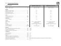
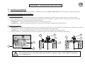
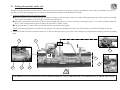
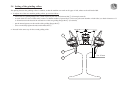
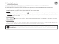
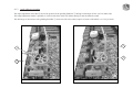
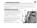
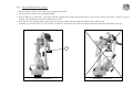
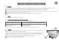
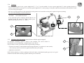
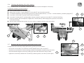
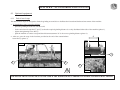
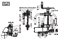
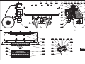
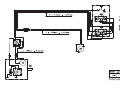
INTRODUCTION Safety has always been an outstanding feature of our machines. However, the new international labour safety regulations prescribe that any machine or instrument be supplied with an instruction note pointing out the possible risks for the user and the precautions to be taken to avoid accidents. In pursuance of these regulations which are imperative for any machine manufacturer anxious to give a maximum of safety to his customers, we urge you to read carefully the following chapters which concern your safety as well as that of your staff. INT_Gb_00002_050504.doc CONTENTS CHAPTER 1 – SAFETY 1.1 1.2 1.3 1.4 Foreword Instructions for safety and general use General safety instructions Special safety instructions 1.4.1 1.4.2 Risks that can be caused by using the "MP23" type profile grinder Safety rules to observe before and during use of the type "MP23" grinder 4.2 4.2.1 4.2.2 General General view Technical specification Weight distribution Machine location in the clearance gauge CHAPTER 3 – INSTALLATION AND USE 3.1 3.2 3.3 3.4 3.5 Installing the grindstone Orientation of the control handle Installing the machine on the rail Setting of the grinding rollers Inspecting the machine CHAPTER 4 - USE 4.1 Conditions of use 4.1.1 4.1.2 4.1.3 4.1.4 4.1.5 Working area and position of the operator Starting up and shutting down the machine Angle adjuster operation Grindstone electric upward and downward translation system user instructions Taking the machine off the track General instructions for storage Special instructions for storage CHAPTER 5 – SERVICING AND MAINTENANCE 5.1 Servicing 5.1.1 5.1.2 5.1.3 5.1.4 5.1.5 5.1.6 5.1.7 CHAPTER 2 – DESCRIPTION OF THE MACHINE 2.1 2.2 2.3 2.4 2.5 Storage 5.2 Engine List of essential equipment and accessories for servicing Cleaning Greasing Checking drive belt tension Checking and adjusting roller slide clearance Replacing the drive belt on the raising and lowering system Maintenance 5.2.1 5.2.2 Preventive maintenance schedule List of wearing parts CHAPTER 6 – ACCESSORIES AND OPTIONS 6.1 Optional hardware 6.1.1 End-of-travel stops CHAPTER 7 – SPARE PARTS CATALOG 7.1 Drawings and parts lists CHAPTER 1 – SAFETY 1.1 Foreword The following set of rules has been drawn up to ensure the application of precautionary principles that help to preserve the safety of persons and property when the machine is in use. Any failure to comply with these rules can have serious repercussions (bodily injury, etc.), and can even be fatal, so we must draw your attention to the fact that all persons involved in the use, maintenance, storage or custody of the machine covered by the present manual must be familiar with these rules. Any users who cause an accident through failure to comply with these rules will be held personally responsible for the results of their actions. 1.2 Instructions for safety and general use All persons using, servicing or repairing this equipment must have undergone the training, possess the skills, and have at their disposal the tools necessary to carry out any such operations. Before using the equipment, even in a maintenance context, it is necessary to read the corresponding instruction manual, together with its appendices, and the safety rules in force in the workplace. Comply carefully with the general safety instructions drawn up for the site by the person in charge of the site, especially if the work is carried out without stopping or diverting traffic. The equipment can only be used, serviced or repaired by competent personnel who have undergone thorough specialized training beforehand. The technical documentation and the instructions are useful in completing the knowledge acquired during the training courses, but they can in no way replace theoretical and practical qualifying training, provided in accordance with good professional practice. If the operating company is not in a position to carry out the necessary training for its staff, at a satisfactory level, the STUMEC/GEISMAR Company is able to provide advice concerning the training programme to be implemented. The training must include an explanation of the various equipment functions, the instructions for use and maintenance, and the safety rules applicable, together with practical exercises. IMPORTANT! All persons using the machine must comply with the labour regulations in force The STUMEC/GEISMAR Company cannot be held responsible for any modifications made without its written approval, or for any assembly work not in conformity with its recommendations, especially in the case of use of parts other than original manufacturer’s parts. SECT_Gb_00003_050503.doc 1.3 General safety instructions x The operator and the working environment Ö To avoid all risks of accident or injury, it is essential to wear: - Sturdy, non-flammable clothing that is suitably close-fitting - Strong, non-slip gloves - Safety shoes - Protective eyewear - Safety helmet - All other equipment necessary on the site or when using the machine Ö In the case of use of ear defenders, the safety instructions in force on the site must be complied with at all times. Ö Make sure that the machine vibrations do not lead to a loss of sensitivity in the hands. Adapt the working periods to the level of vibration caused by the machine, which is shown within the framework of normal use. Ö Do not work with the machine if you are not sure that you can control it correctly. Do not start working with the machine until you are sure that you can do so in full safety, for yourself (good conditions of visibility and lighting) and for other people (work calmly and carefully). Take care to ensure you have a firm, stable footing; all unstable working positions must be prohibited. Ö The user must be in a physical and mental condition enabling work to be carried out without danger. Ö The work area must be free of all obstacles. The work area (and the surrounding areas) must be free of all flammable substances. Ö If anything does not seem clear to you, whether it concerns the machine or the work to be carried out, ask a qualified person for information. Do not base your work on assumptions. Ö For underground use (tunnel or gallery), or in a closed area, make sure there is sufficient ventilation or extraction to avoid the risks generated by inhaling exhaust gases or by their build-up. Ö This equipment must not be used in an explosive atmosphere. Ö Avoid working positions in which exhaust gases could come into contact with parts of the body, whether protected or not. Ö In a general way, take all necessary precautions to prevent flammable products from coming into contact with fire hazards. Ö The operator must ensure that no one else is within the working area. In particular, it is necessary to make sure that in the direction in which the machine is travelling, no one can be hit. If someone is nonetheless in the path of the machine, the operator must stop and warn the person of his passage. Special care must be taken with trolleys that take up the full width of the track and could cause leg injuries if someone is hit. Ö When the machine is installed on the track, it must be handled only by the number of operators strictly necessary for its normal use. Ö As the overall size of the machines does not enable extinguishers to be carried on them, we strongly recommend placing extinguishers of an appropriate type to deal with the fire hazards close to the machine. Ö The user must comply with all the regulatory environmental instructions applicable to the machine in use. SECT_Gb_00004_050503.doc x The operator and the machine Ö Before putting the machine into service each time, check that its condition and its operation are in compliance with the instructions. In particular, make sure that the controls are free and in good working order, and that they are in the “stop” or “neutral” position. Never make any modifications that could affect correct operation of the control systems. Ö All the protective elements must be kept carefully in place and in good condition. Ö Always keep the machine clean and remove any accumulated dust, especially if it could absorb flammable products. Ö Always move forwards when working. Ö When working, always hold the machine with both hands to ensure control at all times, and to be able to use it in full safety. Ö Never bring a machine close to a flame or a source of heat. Ö Never move away from a machine while the engine is running, even when it is idling. Stop the engine immediately if the machine is not in use. After stopping the engine, wait until all moving parts have come to a complete stop. Ö Work on the electrical installations on the machine can only be carried out by suitably qualified persons. Ö Read and make sure you fully understand all the signs placed on the machine, and always comply with all the instructions. Ö The signs placed on the machine include pictograms, manufacturer’s plates, and instruction labels. Make sure they are kept clean and replaced if they have been damaged, or if they are missing or illegible. If one of these elements is on a part that is to be replaced, a new element must be present on the replacement part. Please contact us on this subject. THE MACHINE MUST NEVER BE USED FOR A PURPOSE OTHER THAN THAT FOR WHICH IT IS INTENDED NEVER TOUCH A MOVING PART WITH A TOOL, OR WITH THE HAND, OR WITH ANY OTHER PART OF THE BODY IT IS ESSENTIAL TO STOP THE ENGINE AND SET THE CONTROL TO THE STOP POSITION BEFORE CARRYING OUT: - ANY HANDLING WORK ANY WORK TO CHANGE TOOLS OR SOCKETS ANY WORK INVOLVING FUEL OR OIL (FILLING, TOPPING UP, CHECKING LEVELS, ETC.) ANY REPAIR, MAINTENANCE OR CLEANING WORK SECT_Gb_00005_050503.doc x Using and handling fuel and oil Ö It is essential to stop the engine and set the control to the stop position before carrying out any work involving fuel (filling up, checking the level, draining, etc.). Ö Always keep suitable extinguishers ready for use in all areas where fuel is handled (storage, filling up, etc.). Ö Always store fuel and oil in separate cans specially designed for the purpose and bearing the labels required by regulations. They must be stored in a safe place, well away from all types of fire hazard. Ö Each time a machine is started up, and while it is running, make sure that there are no fuel leaks from any part of the machine. If a leak is suspected, stop the engine immediately and do not restart the machine until the leak has been repaired. Ö Never carry out any work on a fuel tank or handle fuel to fill a tank, or for any other reason, in an area where there could be a fire hazard (such as a burning cigarette, a blowtorch, sparks, etc.) or substances that are incandescent or at a high temperature (such as welding spatters, slag, clinker, etc.). All such work must always be carried out outdoors or in a well-ventilated area. Ö Always turn all mobile phones off while filling a tank with fuel or handling fuel. Ö Carefully tighten the fuel filler cap each time, and check that no fuel leaks from it. Ö Always remove a filler cap slowly, to enable any internal pressure to be released without spraying any fuel out. Take special care if the surrounding temperature is high. Ö When putting fuel in a machine that has heated up, never fill the tank completely. Do not put in more than half to three-quarters of the tank capacity. Ö If fuel starts to boil in the tank when putting fuel in a machine that has heated up, screw the cap on again immediately and leave the machine to cool down. Ö Make sure the fuel used is suitable for the type of engine on the machine. See the user manual for the engine. Ö Do not inhale fuel vapour. Ö If it is necessary to drain the fuel tank, pour the fuel into a container designed for the purpose and bearing the labels required by regulations. Always close them tightly, even if they only contain a small quantity. Never use a glass container. Ö Never use fuel for cleaning work. Use only non-flammable, non-toxic products that are harmless for the user and the equipment. Ö If fuel has been spilt near the filling area for any reason, clean it up immediately. Clean straightaway any spillage of fuel on the skin. Make sure no fuel has been spilt on your clothes; otherwise, change clothes immediately. Remove all rags or other materials used to wipe fuel, and store them in a safe place well away from all sources of heat or combustion. Move the machine well clear of any spilt fuel before starting it up (at least 6 metres away), and do not move any closer to the area while the engine is running. IN CERTAIN CASES HANDLING OIL CAN GIVE RISE TO THE SAME TYPE OF RISKS AS HANDLING FUEL. IT IS THEN ESSENTIAL TO TAKE THE SAME PRECAUTIONS WITH OIL AS THOSE SET OUT ABOVE FOR FUEL. SECT_Gb_00006_050503.doc x Tools to be used on the machine Ö Use only the types of tools intended for normal use of the machine. Ö Measure the speed of all rotating tools at regular intervals. Ö Never use tools at speeds greater than the maximum speed for which they have been designed and approved. Ö Never use damaged tools or tools that have reached their maximum level of wear. x The engine on the machine Ö Never touch the hot parts of the engine, and especially the exhaust pipe. If it is necessary to work on the engine, wait until it has cooled down. Ö Check the engine rotation speed at regular intervals, and especially after fitting tools or reassembling the machine. Adjust if necessary. Ö Never exceed the speed shown in the technical specifications. Ö After starting with the choke, remember to return the choke to the normal running position. Ö Never wind the starter rope around your hand, and never release it suddenly. Ö If the machine does not operate correctly after the engine has been started, stop the engine and inform the head of maintenance. Ö x For petrol engines, use only spark plugs whose tops are as shown in drawing 1 opposite. If the plug is fitted with a screw top, make sure the top is fully tightened. After fitting the spark plug, make sure that the plug cap is in good condition and that it stays firmly on the plug. Carefully check the fastening system to make sure that no sparks can be formed. Using trolleys Ö A machine designed to work on a trolley must not be used without the trolley. The trolley is thus an integral part of the machine. The machine and the trolley must not be used separately. Ö Trolleys whose use is dedicated to a machine must never be used to transport equipment or personnel, or attached to a vehicle. Ö Before fitting the machine on its trolley, it must be placed correctly on the track to ensure that it can run freely. If it is on a sloping section of track, make sure the trolley is kept immobile while the machine is being put on the track or taken off it. Ö Attention, the trolley takes up the full width of the track and can cause injuries to the legs if it hits someone. SECT_Gb_00007_050503.doc 1.4 Special safety instructions 1.4.1 Risks that can be caused by using the " MP23 " type profile grinder The main risks involved in this machine for the operator and the environment are : - Fires subsequent to handling of fuel. - Fires caused by sparks igniting flammable materials. - Violent disintegration of grindstones used under abnormal conditions. - Injuries caused by projected sparks (you should make especially sure that you protect your eyes) or, possibly, projections of grindstone debris. - Severe burns if a part of your body comes into contact with the grindstone while it is running. - Inhalation of particles generated by grinding (wear a protective appliance that prevents you from breathing-in such particles). IMPORTANT Because the motor is able to tilt while you are working, you absolutely must obey the rules below : ¾ Always return the grindstone to the vertical position, stop any grinding and stop the motor before removing the cap from the fuel tank. ¾ Never fill the fuel tank to more than ¾ of its capacity (to prevent fuel leakage when the motor is tilted while running). ¾ Never perform an operation on a fuel tank or handle fuel, whether for filling or any other reason, in an area where there may be the following hazards: a source of fire (for example, a lit cigarette, a blow torch, sparks, etc.) or material that is either incandescent or at a high temperature (for example, remains from welds, various forms of dross and slag, etc.). Always perform these tasks outdoors and in properly-ventilated premises. Properly lock the fuel tank cap into position after each time you open it, and make sure that it does not allow fuel to leak out. ¾ Refer to sections §1.2 "General use and safety instructions" and §1.3 "General safety requirements". 1.4.2 Safety rules to observe before and during use of the type "MP23" grinder ¾ In addition to the clothing stated in section §1.3 "General safety requirements / The operator’s environment", people using this equipment must also wear: masks or glasses; helmet; apron; gaiters or boots made of fireproof material. Similarly, you are recommended to use a means of protection to prevent you from breathing-in dust from grinding. ¾ Do not use damaged grindstones or grindstones with splits or cracks ¾ When using a new or newly-remounted grindstone, run the machine for 30 seconds without doing any grinding. When doing this test, make sure that all people apart from the actual operator are at a safe distance away from the machine; only the actual operator should be at the machine's controls, staying out of the plane of rotation of the grindstone and remaining ready to stop the machine if necessary. ¾ During grinding, do not position yourself in direct line of contact with sparks from grinding. If necessary, set-up a screen that prevents the jet of sparks from reaching anywhere hazardous (danger of starting a wild fire during summer weather). ¾ Do not allow impacts on the grindstone while working; this could cause it to violently disintegrate. ¾ Make sure that the grindstone never comes into contact with a crosspiece or ballast, or any other foreign object. ¾ Before starting the machine, check that the grindstone protective cover is in satisfactory condition and is properly secured. Never make any modifications to it. ¾ Always install a new cover after a grindstone has violently disintegrated and whenever it no longer seems strong enough. ¾ Perform measurements of running speed at regular intervals of time, notably after reassembling the machine, and correct if necessary. ¾ Only used authorized types of grindstones, as regards both size and composition. ¾ Never use grindstones at speeds higher than the maximum speed recommended by the manufacturer, which should be marked on each grindstone. ¾ Before taking the machine off the rails, or between two grinding sequences requiring you to move the machine, always switch the motor off and immobilize sideways movement of the machine by using the ratchet mechanism provided for the purpose. ONLY USE GRINDERS: Î Of which the maximum rated speed is higher than the maximum running speed of the grinder holding shaft, which is marked on the machine. Î Of which the outside diameter is less than or equal to the maximum authorized diameter, which is marked on the machine. Î Autorized by the regulation in application for this type of machine. CHAPTER 2 – DESCRIPTION OF THE MACHINE 2.1 General Manufacturer: SOCIETE TURRIPINOISE DE MECANIQUE Route d’Italie 38110 LA TOUR DU PIN Description of the equipment: Profile grinder Type: MP23 The MP23 has been designed for grinding rail heads and rail welds, including the curvature and the sides. Its robust construction and exceptional performance make the machine very easy to use. Its whole design is based on the most modern technologies available in the machine tools industry. Thanks to the 180° head angle adjustment system, the MP23 can work over the whole profile of the rail without the operator having to turn the machine round. Therefore, the operator remains within the track at all times. This machine is fitted with an electric upward and downward translation system for the grindstone. The system is controlled by two buttons located on the upper part of the machine handle. All the controls are therefore within reach of the operator. A system of stops limits the grindstone downward travel to prevent any operating error that would result in making a depression in the rail. The machine moves along the track by means of 6 flat rollers (3 rollers on each side) ensuring perfectly even grinding. The machine is fitted with two handling arms that fold away to reduce the overall measurements of the machine during transport and storage. 2.2 General view A H B J C K D L E F M G N P Ref. Description A Counterbalance beam B Machine handle C Lifting ring D Control handle E Remote engine stop switch F Buttons controlling the electric upward and downward translation system for the grindstone G Grinding head angle adjustment wheel H Counterbalance beam locking handle J Foldaway transport arms (x2) K Engine L Upward / downward translation manual control M Grindstone guard N Grindstone downward thrust P Grinding head 2.3 Technical specification ENGINE MODEL HONDA GX 200 4stroke HONDA GX 270 4stroke Machine dimensions Length / width / height ……………………………………... mm 1600 / 630 / 880 1600 / 630 / 880 Weight Machine (weight empty)……………………………............. Machine (ready for use)………………………………..…… Counterbalance beam………………………………………. End-of-travel stops (x2)...………………………………...… kg kg kg kg 84 90 5 4,6 95 102 5 4,6 Noise Acoustic pressure level …………………………………….. Acoustic power level….. …………………………............... dBA LwA 82 89 84 92 Vibrations Level of vibration…………………………………………... ms -2 5,6 6,5 4,8 (= 6,5hp) at 3600 rpm Unleaded petrol Automatic return cord starter 3,6 313 (230 g/hp/h) 6,6 (= 9hp) at 3600 rpm Unleaded petrol Automatic return cord starter 6 313 (230 g/hp/h) Engine Power rating………………………………………………… kW Fuel…………………………………………………………. …… Starting……………………………………………………… ……. Fuel tank capacity…………………………………………... liter Fuel consumption…………………………………………... g/kW/h Machine Motor adjustment speed (maximum speed)...…..………....... Grindstone running speed…………………………………... Maximum diameter of grindstone…...……………………... rpm rpm mm Grindstone Outside diameter……………………………………………. Inside diameter……………………………………………... Height……………………………………………………..... Authorized grindstone running speed………………………. Authorized grindstone peripheral speed……………………. Composition of grindstone…………………………………. Heightwise grindstone travel……………………………….. mm mm mm rpm m/sec …… mm 3600 4000 150 150 55 72 6370 50 Resinoid grindstone (grindstone composed of synthetic binders) 65 2.4 Weight distribution The diagram below shows the weight distribution as a percentage of machine weight. See §3.3 “Putting the machine on the rail” to determine the number of persons needed for handling operations. 57% 43% 2.5 Machine location inside the clearance gauge The diagram below shows the dimensions of the machine as compared with the lower UIC 505-1 clearance gauge (track with a nominal gauge of 1.435 m). CHAPTER 3 – INSTALLATION AND USE 3.1 Installing the grindstone The operations of mounting and dismounting the grindstone should be done with the engine switched off and when the machine is resting on the ground. To fit a grindstone to the machine, proceed as follows : Î Dismounting the grindstone : 1 Lower the grindstone as far as possible and then remove the grindstone casing Ref.ԙ by taking out the 2 screws Ref.Ԙ (17 mm box wrench). 2 Hold the spindle Ref.ԛ using a 27 mm open end wrench and then unscrew the “grindstone + grindstone holder” unit using a second 27 mm wrench. 3 Remove the grindstone Ref.ԝ from the grindstone back plate Ref.Ԝ : - assembly Pic.2 >> Take out the fastening screws Ref.Ԛ (13 mm open end wrench). - assembly Pic.3 >> Hold the grindstone holder Ref.Ԝ (27 mm open end wrench) and untighten the grindstone Ref.ԝ. Î Mounting the grindstone : 5 - assembly Pic.2 >> Position the grindstone Ref.ԝ in such a way that the internal Ø fits over the flange on the grindstone back plate Ref.Ԝ. Insert the fastening screws Ref.Ԛ in the grindstone Ref.ԝ until they touch the back plate. Then tighten them. - assembly Pic.3 >> Hold the grindstone holder Ref.Ԝ (27 mm open end wrench) and tighten the grindstone Ref.ԝ. 6 To fit the “grindstone + grindstone holder” unit, carry out operations 2 and 1 in the opposite order as compared with removal. 3 4 4 6 5 1 5 6 1 2 Pic.2 THE Pic.3 GRINDSTONES YOU USE SHOULD MEET THE TECHNICAL SPECIFICATIONS STATED IN DATA / GRINDSTONE" § 2.3 "TECHNICAL 3.2 Orientation of the control handle The orientation of the control handle on the machine can be modified to suit the operator’s working position. The control handle can be placed in the three different positions shown below : 1 2 3 4 3 4 1 2 x To move the control handle from position 1 to position 2 : - slightly loosen nut Ref.Ԛ and then swivel the handle through 90°. - tighten nut Ref.Ԛ. x To move the control handle from position 1 to position 3 or 4 : - fully unscrew nut Ref.Ԛ, and then remove the collar Ref.Ԙ from the button box Ref ԙ. - swivel the button box Ref.ԙ through 90° until the shaped section lines up with the machine handle Ref ԛ. - put the collar Ref.Ԙ back in place in the corresponding position and then tighten nut Ref.Ԛ until it comes into contact with the handle. - adjust the position of the handle, and then fully tighten nut Ref.Ԛ. 3.3 Putting the machine on the rail The task of putting the machine on the rail and removing it must be carried out by at least two persons. Nevertheless, if the work area is difficult to reach, it is necessary to ensure that enough persons are present to ensure that the machine can be handled in full safety x To put the machine on the rail, proceed as follows : ݢPick the machine up by its lifting ring Ref.ԝ and put it in place on the rail using a crane or any other lifting equipment with a lifting capacity exceeding the weight of the machine as set out in §2.3 “Technical specifications”. ݣInsert the counterbalance beam Ref.ԙ into the hole provided and push it in as far as it will go so that the pin Ref.ԛis in contact with the clamp ring Ref.Ԛ. Then lock the beam in place by turning the lever Ref.Ԙ until it is tight. ݤLift the stand Ref.Ԟ so that it does not interfere with the movement of the grinder. NOTE : If no lifting equipment is available on the worksite, move the two handling arms Ref.Ԝ out and use them to position the machine on the rail. x Once the machine has been positioned on the rail, it must be chocked in place to prevent it from rolling away unattended and injuring someone by hitting them. 5 1 6 5 7 2 3 4 IT IS IMPERATIVE THAT THE ENGINE BE STOPPED WHEN PUTTING THE MACHINE ON OR REMOVING IT FROM THE TRACK 3.4 Setting of the grinding rollers The spacing between the grinding rollers is settable, so that the machine can work on all types of rails, whatever the rail head width. x To adjust one of the two machine guiding rollers, proceed as follows : - remove the two guiding flanges Ref.Ԛ held in place by the nuts and locknuts Ref.Ԙ (25 mm pin wrench) - on each of the two axes of roller axles, remove or add the number of spacers Ref.ԙ necessary (the same number on both sides ) to obtain clearance of 5 to 10 mm between the head of the rail and one of the two guiding flanges Ref.Ԛ (see sketch). - put the unused spacers on the outside of the guiding flanges Ref.Ԛ. - screw on and fully tighten the nuts and locknuts Ref.Ԙ. x Proceed in the same way for the second guiding roller. 1 2 5 to 10 mm 3 3.5 Inspecting the machine Each part of the machine must be examined by a person with the appropriate skills before starting-up, so as to identify any problems. This inspection mainly involves a visual and functional check. The inspection phase will let you make sure that the various parts are safe, and that they have not been damaged during transportation and storage. x Check the fabricated assemblies (only do this with the motor switched off) Visually check that there are no exterior defects, distortion, surface cracks, wear or corrosion marks. x Check levels (only do this check with the motor switched off) : make sure you do read §1.3 "General safety requirements", sub-section §: "Using and - Fuel level: check the fuel level, and top-up where necessary ( handling fuel" before you do any operation). - Motor oil level: check the motor oil level by inspecting the dipstick, and top-up where necessary. The level should be slightly below the maximum level mark on the dipstick, but never higher. x Check the safety devices Switch on the motor ( : make sure you do read §4.1.2 " Starting-up and shutting-down the machine "), and check that the safety devices work properly (remote motor shutdown). x Check the functioning Check the good working order of the controls. Check that the upward / downward translation control switch and the grinding head angle adjustment wheel are working correctly : during the operation, controls moving must be as smooth as possible, without any hard point. IF YOU IDENTIFY A PROBLEM WHILE DOING THIS VISUAL INSPECTION OR WHEN YOU ARE USING THE MACHINE, THEN THE MOTOR MUST BE RESTORED TO PROPER WORKING ORDER BY APPROPRIATELY-SKILLED PERSONNEL OR BY THE MANUFACTURER BEFORE IT IS USED AGAIN. CHAPTER 4 – USE 4.1 Conditions of use 4.1.1 Movement zone and position of the operator x The operator’s working zone is located within the two vertical limits defined by the UIC 505-1 clearance gauge (Cf. §2.5 “Machine location in the clearance gauge”) >> Photo n°1. x During work, the operator must always be in the position shown on photo n°2 with his right hand firmly grasping the control handle and his left hand holding the handle of the tilt wheel. This working position ensures full control of the machine. If the operator is in the working position described above, it is impossible for him to move outside the two vertical limits defined by the UIC 505-1 clearance gauge. Photo 2 Photo 1 MOVEMENT ZONE OF THE OPERATOR OPERATOR'S POSITION 4.1.2 Starting-up and shutting-down the machine Refer to the engine manufacturer's instructions to determine the position of the controls to be operated to start and stop the engine. Î Starting-up : x Check that the remote engine stop switch Ref.Ԙ is correctly in position 1 and move the choke lever to the close position (if necessary > do not use the choke if the engine is warm or the air temperature is high). x Start the engine and leave it running at idle speed for a short time until the engine speed stabilizes and the engine warms up. As the engine warms up, gradually move the choke lever to the open position. x When the engine is warm, increase the engine speed by moving the control to the max. position (factory setting). Î Shutting down the machine : x Stop the engine by moving the remote engine stop switch Ref.Ԙ to one of the two 0 positions. 1 THE MACHINE MUST ONLY BE STARTED ON THE TRACK 4.1.3 Angle adjuster operation The angle adjustment wheel Ref.ԙ moves the position of the grinding head Ref.Ԙ through a total angle of 180° (90° on either side). This angle adjustment makes it possible to work on both sides of the rail without having to turn the machine round. The full range of movement of the grinding head Ref.Ԙ (from one side to the other) requires 21 turns of the wheel (i.e. 8°34’ per turn). 1 1 2 2 OUTSIDE TRACK MAXIMUM POSITION >> -90° INTERNAL TRACK MAXIMUM POSITION >> +90° 4.1.4 Grindstone electric upward and downward translation system The grindstone height is adjusted using an electric system controlled by two buttons Ref.ԙ andRef.Ԛ, located on the machine handle. When pressing on the button Ref.ԙ ( Å ) the grindstone moves upward, when pressing on the button Ref.Ԛ ( Æ ) the grindstone moves downward. One revolution of the translation system Ref.ԛ corresponds to a grindstone change of height of 2,5mm. Therefore, to get an indication of the height change, the operator can observe the revolution angle of the translation system Ref.ԛ. In case of a malfunctioning of the electric translation system, the translation upwards/downwards of the grindstone can be operated manually. This manual control is made of 3 knobs located on the body Ref.ԛ. Turn the body to the right to lower the grindstone, and turner the body to the left to raise it. To limit the downward stroke of the grindstone, the machine is equiped with a downward thrust Ref.Ԙwhich prevents the operator from doing a depth on the rail profile when grinding. It is IMPERATIVE to adjust this stop on the crown of the rail before starting the grinding operation. To adjust the grindstone downward thrust Ref.Ԙ, proceed as follows : - place the grinding head Ref.Ԝ in the vertical position (grinding the crown of the rail). - fully unscrew the knurled knob on the grindstone downward thrust Ref.Ԙ. - gently bring the grindstone just in contact with the rail, pushing by short pulses on the button Ref.Ԛ (so that to get just a few sparks) >> do this in an area near the weld that does not require grinding, i.e. in a place where the rail profile is correct (check that at this point the rollers are in fact positioned on a correct profile, where there are no burrs, dips or bumps). - screw down the knurled knob on the grindstone downward thrust Ref.Ԙ until resistance is felt. - raise the grindstone so that it is in a plane above the weld. 4 Start by grinding down the weld to about one millimetre above the surface of the rail. To do this, work in rapid successive passes by moving the machine in short forwards and backwards movements along the rail. Start with the horizontal surface and then grind down the sides (see §4.1.3 "Angle adjuster operation"). To finish off, readjust the grindstone downward thrust (to compensate for grindstone wear) and complete the grinding of the whole profile. Do this until all traces of the weld have been removed. Finish by making the joint flush over about 10 cm on either side of the weld. Check the evenness with a straight edge. If these instructions are followed, it is impossible to make a depression. 1 5 2 3 4.1.5 Taking the machine off the track Depending on the situation (the time available to take the machine off the track), the machine is taken off the track using either a) the “Normal Procedure” or b) the “Emergency procedure”. 1 a) Normal procedure x Raise the grindstone to ensure a clearance of at least 3 mm between it and the crown of the rail. x Move the grinding head Ref.ԙ to the vertical position. x Reduce the engine speed and then stop the engine by setting the remote engine stop switch Ref.Ԙ tQ 0. Then wait until the grindstone stops rotating. x Take the machine off the track by carrying out in reverse order the procedure for “Putting the machine on the rail” set out in §3.3. Î As described in that paragraph, the “MP23” type profile grinder can be put on the track or taken off the track by two persons. However, if the work zone is difficult to access, it is necessary to ensure that enough persons are present to enable the machine to be handled under good conditions. b) Emergency procedure x Stop the engine by moving the remote engine stop switch Ref.Ԙ to one of the two 0 positions. x Grasp the machine using the two handling arms Ref.Ԛ located on each side of the machine and quickly take it off the track. IMPORTANT: after using the emergency procedure to take the machine off the track, it is essential to make sure that none of the machine parts have been damaged and that the grindstone is in good condition. The machine must be inspected and repaired if necessary before it is started up again. 2 3 4.2 Storage 4.2.1 General instructions for storage During periods when the equipment is not being used, it is essential to store it correctly in order to maintain its original condition. Equipment that is not stored correctly may cause damage when next used. Therefore it is important that personnel responsible for storage operations take the greatest care in carrying them out and comply scrupulously with the required precautions. Ö Storage protection system The choice of storage protection system depends on 2 main factors : - length of storage - storage conditions: storage "out in the open" (exposed to the weather) and storage "under cover" (building, closed warehouse, open warehouse, tarpaulin, etc.) The equipment should only be put in storage after it has been run in. Arrangements must be made to allow easy access around the equipment for carrying out maintenance operations. Ö Storage areas Generally speaking, areas used for the storage of equipment must provide the best possible protection against : - dust and exhaust gases, humidity - direct sunlight - rapid temperature changes Ö Putting into storage The condition of equipment when it is returned to service after storage depends on the way it was prepared and protected before being put into storage : - cleaning of the equipment (protect moving parts with grease after cleaning). - technical inspection to find any faults. 4.2.2 Special instructions for storage Ö When putting the machine into long storage, empty the fuel tank. Ö Never store the machine with a grindstone fitted. Ö Store grindstones in a dry place, away from freezing, sunlight and strong heat. Position them so there are no stresses upon them, in order to prevent bowing. They should not be stored for longer than 2 years. Ö If the engine is left stopped lying canted, oil passes into the cylinder and the carburettor and the engine will not start. Therefore, the machine must be stored with the stand Ref.Ԙ in position. The stand is designed to keep the engine horizontal during storage. 1 CORRECT STORAGE INCORRECT STORAGE CHAPTER 5 – SERVICING AND MAINTENANCE 5.1 Servicing It is necessary to have undergone appropriate training, possess the required skills and have the right tools to service and repair this equipment correctly. All servicing and repair work on this equipment must be carried out by competent staff with a good knowledge of general mechanics. Before carrying out any servicing work, stop the engine (leave the switch on the stop position) and wait for it to cool down. All waste products remaining after servicing and maintenance operations (fluids, filters, used rags, etc.) must be disposed of in accordance with the regulations in force and the directives for protection of the environment. Replace or repair any worn, damaged or missing parts immediately when there is a possible safety hazard. 5.1.1 Engine Comply strictly with the manufacturer’s instructions. 5.1.2 List of essential equipment and accessories for servicing The following tools are necessary for correct servicing and maintenance operations : Servicing tools (supplied with the machine) 10,13 and 17 mm box wrenches 2 x 27 mm open ended wrenches 25 mm pin wrench Servicing and maintenance tools (not supplied with the machine) Flat bladed screwdriver 10 mm open ended wrench 3 and 5 mm hex head keys This tool list does not exclude the usual, essential servicing equipment such as rags, brushes, grease, etc... 1 5.1.3 Cleaning Make sure the machine is always kept as clean as possible. The care taken in cleaning the machine directly influences the length of its service life and its correct operation. +2 Carefully clean the machine using a clean rag or a blow gun, taking care to remove all dirt that has gathered on it, especially close to the moving parts. As a precaution, always wear gloves to avoid cuts and burns on the hands. Clean the roller slides under the protective cover at regular intervals. To do so, take out the six screws Ref.Ԙ holding the cover Ref.ԙ in place (10 mm box wrench). Clean both sides of the machine. Do not oil or grease the slides after cleaning them. 2 5.1.4 Greasing - Once a week, put grease in the 3 grease nipples Ref.Ԙ, Ԛ etԛ on the machine. To access grease nipple Ref.ԛ, tilt the grinding head to its extreme inner position on the track. To access the grease nipple Ref.Ԙ, remove plug (27 mm open ended wrench) and turn the body Ref.ԙ until you can see the grease nipple. - After any servicing operation on the transmission casing (where are located the conical gears), replace the grease (0,180kg). Use one of the following recommended grease : - TOTAL MULTIS EP 200 - KLÜBER NATOSBIN B 1600 EP 3 or any equivalent grease complying with the DIN 51 354 standard (grade 00 grease for highly loaded gears. Operational temperature -20°C to +120°C). 1 2 5.1.5 Checking drive belt tension (must be done with the engine stopped) An automatic tensioning system is fitted on the machine. The correct tension is automatically set when tightening / untightening the screw Ref.ԝ. 5 Every 50 hours of work, set the belt tension by proceeding as follows : - loosen the screw Ref.ԝ which holds the tensioning roller Ref.Ԝ in position (13 mm wrench). > the necessary tension on the belt is applied automatically by the spring. - tighten the screw Ref.ԝ. NOTE: When replacing or a belt or putting a belt back in place, check that the pulley grooves are in good condition and clean them carefully, together with the groves in the belt. 6 4 5.1.6 Checking and adjusting roller slide clearance Every 100 hours of use, it is advisable to check the roller slide clearance and adjust it if necessary. To adjust the clearance, proceed as follows : n o p q r s Set the grinding head to its vertical position. Remove the cover Ref.Ԙ after taking the six screws Ref.ԙ out (10 mm box wrench). To facilitate adjustment, cancel the spring pressure by removing bracket Ref.ԛ (3 screws - 5 mm hex head key) and then spring Ref.Ԛ. Loosen the 3 screws Ref.Ԟ by half a turn (5 mm hex head key). Loosen the 3 locknuts Ref.ԝ, and then adjust clearance using the 3 pressure screws Ref.Ԝ (3 mm hex head key). Once the clearance has been adjusted, retighten the 3 locknuts Ref.ԝ while keeping the 3 pressure screws Ref.Ԝ at the desired setting. Put the various elements back in place in reverse order as compared with the removal procedure. t 5 6 7 +2 1 3 4 2 9 5.1.7 Replacing the drive belt on the raising and lowering system 10 To replace the drive belt on the raising and lowering system, proceed as follows : - take out the 2 screws Ref.Ԡ (10 mm box wrench) and then remove the cover Ref.ԟ. loosen the screws Ref.ԡ (5 mm hex head key) and Ref.ԣ (flat blade screwdriver) by a few turns. fit the belt and then adjust its tension by pulling the motor and reduction drive Ref.Ԣ back. tighten the screw Ref.ԡ and then the screw Ref.ԣ, and then put the cover Ref.ԟ back in place. 11 8 12 5.2 Maintenance 5.2.1 Preventive maintenance schedule PERIODICITY ITEM NATURE OF THE OPERATION Complete appliance Inspecting the machine Complete appliance Cleaning the machine as a whole using a clean rag or a blow gun to remove all dirt from the machine Greasing Greasing Adjusting tension Before each use Before each use Every week Every 50 hours Every 100 hours Presence of obvious signs of wear or incorrect operation X Ref. Chap.3 - § 3 X Chap.5 § 1.3 X Chap.5 § 1.4 X Chap.5 § 1.5 Drive belt X Replacement Cleaning X Chap.5 § 1.5 Chap.5 § 1.3 Roller slides Checking clearance (adjusting if necessary) Drive belt on the raising and lowering system Replacement X Chap.5 § 1.6 X Chap.5 § 1.7 NOTE: These recommendations are not limitative. Continual surveillance of the machine and properly-organized preventive maintenance will extend the machine's working life. 5.2.2 List of wearing parts (this list does not include any engine parts) The wearing parts for the machine and the conditions for their replacement are set out in the list below. Nonetheless, it is essential to replace or repair immediately all worn, damaged or missing parts, if a safety risk is involved. Description Ref. Qty Conditions for replacement Tightness joint G 45 x 52 x 4 HWM 1 Tightness joint Ø 40 x 52 x 7 DGM 1 Tightness cap JVY 2 Belt 13 J – L = 813 JTD 1 Belt 170 XL JPU 1 Stop switch HBD 1 Seal n°26 HWG 1 Scraper seal AS 22 - 28 - 5 - 9 KWH 1 O-ring n°8 SS 1 Rubber handle 36151 1 Rubber handle Ø27 LZ 5 Gas spring C = 80 – 700 N JPB 1 Oil leak or incorrect operation Bellows V 6 - 639 HXC 1 Damage Oil leak or incorrect operation Wear or breakage Breakage Incorrect operation or switch broken Oil leak or incorrect operation Wear or breakage CHAPTER 6 – ACCESSORIES AND OPTIONS 6.1 Optional equipment 6.1.1 End-of-travel stops The end-of-travel stops are designed to limit the grinding area and also to facilitate the forward and backward movement of the machine. x To install these stops, proceed as follows : - place the grinding head in line with the weld. fit the end-of-travel stops Ref.Ԙ and ԙ so that the required grinding distance is evenly distributed either side of the machine (photo 1). tighten the tightening levers Ref.Ԛ. push the machine to contact a stop and check that measurement "d" is the correct grinding distance (photo 2). x After use, store the stops in the locations provided at the end of the counterbalance beam Ref.ԛ (photo 3). d Photo 1 Photo 2 1 3 2 4 Photo 3 THE END-OF-TRAVEL STOPS MUST NOT BE USED IF THE WORK IS BEING CARRIED OUT WITHOUT STOPPING RAIL TRAFFIC CHAPTER 7 – SPARE PARTS CATALOG 7.1 Drawings and parts lists CH7_Gb_00032_050601.doc IMPORTANT Afin que votre commande de pièces de rechange soit suivie d’une livraison prompte et correcte, bien indiquer : - Le rep., le nombre et la désignation des pièces de rechange - Le type et le n° de série de la machine (plaque sur le châssis) ********************************************************************* IMPORTANT To ensure that you are delivered promptly and correctly after placing an order for spare parts please state: - the Reference, number and description of the spare parts - the type and serial number of the machine (to locate this number, look at the plate on the chassis) ********************************************************************** WICHTIG Um uns eine schnelle und fehlerlose Erledigung lhres Ersatzteil-Auftrages zu erlauben, bitten wir Sie um folgende Angaben : - Seriennummer und Baujahr der maschine - Benennung und Bestellnummer der Ersatzeile CDE_Gb_00033_050504.doc 71 000 M 03-05 Ref. Qty 71 095 71 097 71 098 71 099 71 100 71 101 71 102 71 103 1 1 1 1 1 1 1 1 Description Cap Pulley 60 T Pulley 30 T Hub Reducer casing Belt casing support Belt casing Pulley flange Ref. GQ JX MA MC VZ ADV AIU AIX ATE AVW BUN DAV ENK EQE FKY FWY HNS JPT JPU Qty 4 2 3 1 2 2 6 1 3 1 3 4 1 1 3 3 4 1 1 Description Screw H 6 x 10 Screw Chc 6 x 16 Knob Ø 25 Screw Hc 6 x 10 flat end Screw H 6 x 12 Washer W 6 Washer W 5 Nut Hm 6 Pin M 8 x 22 Screw Chc 6 x 60 Washer JZC 6 Washer DI 6 Screw F 6 x 60 Stuffing box n° 7 Screw Chc 5 x 25 Screw Chc 5 x 10 Screw Fhc M 4 x 10 Gearmotor 12 V Belt 170 XL 71 000 Y (1/2) 05-05 Ref. Qty 11 050 16 027 30 283 34 010 56 039 71 010 71 011 71 012 A 71 013 A 71 014 71 015 71 016 71 017 71 018 71 019 71 020 1 1 7 1 2 1 1 1 1 1 1 1 1 1 1 1 Description Knob Washer Ø 17,1 x 25 x 4 Pin M 10 x 46 Washer Ø 12,2 x 25 x 3 Felt blanking plug Articulation axle Transmission shaft Sleeve Receiving pinion hub Spindle Grinding wheel adjusting screw Grinding wheel adjusting nut Nut cage Spacer Nut Handwheel bearing Ref. Qty 71 021 71 022 71 023 71 025 71 027 71 029 A 71 044 71 056 A 71 057 71 058 71 076 71 077 71 078 71 087 71 089 1 1 1 1 1 1 1 1 1 1 1 1 1 4 1 Description Key Thrust nut Brake washer Thrust screw Pinion crosspiece Obturator Bevel gear 28 T. Centre frame Left frame Right frame Sleeve Cap Stop washer Centring pin Ø 8 Plug 71 000 Y (2/2) Ref. B AP AT BR CM CT DA DG EI EP GG GM KH OH OI SS TQ Qty 8 4 1 1 2 1 1 2 1 5 2 1 12 2 1 3 7 05-05 Description Screw Chc 8 x 20 Screw H 8 x 20 Circlips 30 e Screw Chc 10 x 30 Thrust ball bearing 51103 Brake washer MB 6 Cap nut H 8 Circlips 40 i Washer W 10 Washer M 6 U Bearing n° 6203 EE Tightening nut KM6 Washer W 8 Tightening nut KM1 Brake washer MB1 O-ring n° 8 Stop nut H 10 Ref. Qty TS VN AAA AAX ABZ ADL BAM BAN BTN COC DGM GGJ HWG HWH HWJ HWK HWL HWM JPK JVZ 5 1 5 1 1 8 1 1 1 1 1 2 1 1 1 1 1 1 1 Description Pin M 6 x 24 Bearing n° 6007 EE Stop nut H 6 Bearing n° 6006 EE Lubricator BEC M 6 Washer Z 10 U Tightening nut KM2 Brake washer MB2 Elastic ring 7015-8 Screw Hc 6 x 6, bowl end Tightness joint Ø 40 x 52 x 7 Bearing n° 61906 Seal n° 26 Scraper seal AS 22 - 28 - 5 - 9 Needle bearing HK40 - 16 Needle bearing HK45 - 16 Stop segment BR 52 Tightness joint G 45 x 52 x 4 Shims (Ø 15,2 x 21) Key BR 5 x 5 x 15 - T 120 71 000 AA 07 - 06 Ref. Qty 558 B 11 062 11 063 11 064 17 849 54 025 71 045 C 71 046 A 71 092 71 143 71 144 1 1 1 1 2 1 1 1 4 1 2 Description Locking handle Tightening screw Tightening handle Crutch Locking strap Locking strap Engine fixing plate Outrigger support Spacer Ø 8,5 x 30 x 8 Elastic stud support Carrying arm Ref. Qty B Q AZ BN EI FG GN HA KH LZ MA PJ PR RR RY SM XI AFK AHQ CRJ DCH ECB FDJ FPM FYC HXC JSW 6 4 4 1 4 10 2 8 12 2 1 4 1 4 1 2 2 4 1 1 1 1 1 3 4 1 1 Description Screw Chc 8 x 20 Nut H 8 Nut H 10 Elastic pin Ø 4 x 20 Washer W 10 Washer M 8 U Screw Chc 8 x 16 Washer M 10 U Washer W 8 Rubber handle Knob Ø 25 Grommet Nut H 5 Screw H 10 x 45 Washer M 5 U Nut Hm 8 Stop nut H 10 Stop nut H 8 Washer DE 5 Bridge rectifier Elastic pin Ø 4 x 18 Clamp Screw Cs 5 x 25 Plug Elastic stud 520027 Bellows V 6 - 639 Gas spring C = 80 - 800 N 71 000 AB 07 - 06 Ref. Qty 36 151 71 147 71 148 71 149 71 150 71 151 1 1 1 1 1 1 Description Rubber handle Button box Cover Washer Handle Locking strap Ref. Qty CE DQ GL TR AFK CJW DRF GDX HBD HEU HGC JVY 4 2 6 1 2 1 1 1 1 1 2 2 Description Screw Cs 4 x 10 Screw Cs 4 x 16 Washer DI 4 Stud M 8 x 27 Stop nut H 8 Cord-eye Stuffing box n° 9 Counter nut n° 9 Stop switch Screw Fhc 8 x 16 Switch Tightness cap 71 000 AC 07 - 06 Ref. Qty 3 308 71 048 A 71 053 71 146 71 146 A 71 146 B 71 146 C 71 146 D 71 146 E 71 146 F 71 146 G 71 146 H 2 1 1 1 1 1 1 1 1 1 1 1 Description Washer Ø 21,5 x 32 x 3 Roller Roller axle Outrigger (1435 track gauge) " (1524 track gauge) " (1600 track gauge) " (1668 track gauge) " (1676 track gauge) " ( 914 track gauge) " (1000 track gauge) " (1050 track gauge) " (1067 track gauge) Ref. ET AKC Qty 2 1 Description Elastic pin Ø 4 x 40 Elastic pin Ø 6 x 70 71 000 AD 07 - 06 Ref. Qty 11 063 27 114 45 424 71 107 A 2 2 2 2 Description Tightening handle Screw Spacer Thrust Ref. AFK DCH EJS JPZ Qty 2 2 2 2 Description Stop nut H 8 Elastic pin Ø 4 x 18 Screw Chc 8 x 65 Elastic pin 511312 71 000 AE 07 - 06 Ref. Qty 17 082 71 028 71 030 A 71 070 A 71 090 2 1 1 2 8 Description Spring Stone holder Grindstone casing Ø 150 x 72 Deflector Deflector ring * Grindstone type 6 - Ø 150 x 72 x 4 M8 / Ø 90 - 50 m/s Ref. Qty L AF DE EI EP JD KH ADV 2 4 4 2 4 4 4 4 Description Screw H 10 x 20 Screw H 8 x 16 Nut H 6 Washer W 10 Washer M 6 U Screw H 6 x 25 Washer W 8 Washer W 6 71 000 AH 09 - 06 Ref. Qty 760 11 042 11 060 17 849 37 206 45 239 54 017 71 059 71 060 71 063 71 066 71 067 71 068 71 091 71 093 71 094 71 144 71 145 71 154 71 156 71 157 71 170 71 171 1 1 1 2 1 1 2 1 1 1 1 1 1 1 1 1 1 1 1 1 1 1 1 Description Spring Washer Ø 20,2 x 30 x 3 Handle axle Strap Stop ring Washer Ø 20,1 x 40 x 4 Swivel support Toothed sector Lever Toothed sector axle Right angle Left angle Inclination handwheel Screw protector Thrust cage Swivel support Carrying arm Carrying arm support Handwheel handle Protective plate Spacer Inclination screw Nut Ref. Qty R BB BC CG EM EP FF FG GP GX KH LZ SM UA VZ XQ ABZ ADV AEJ AFK BBP BUN CNC EHP FDK JVZ 5 1 1 1 2 12 2 4 8 4 2 3 2 4 1 1 2 12 1 12 2 2 8 2 1 1 Description Screw H 6 x 20 Screw ST 10 x 10 flat end Steel ball Ø 8,7 Nut H 14 Tightening nut KM 4 Washer M 6 U Screw H 8 x 25 Washer M 8 U Pin M 8 x 32 Screw H 6 x 30 Washer W 8 Rubber handle Nut Hm 8 Swivel GE 15 D Screw H 6 x 12 Elastic pin Ø 5 x 35 Lubricator BEC M 6 Washer W 6 Washer DE 14 Brake nut H 8 Screw H 8 x 12 Washer JZC 6 Washer Z 8 U Combined bearing RAX 720 Ring PAP 2020 P10 Key BR 5 x 5 x 15 - T 120 71 000 AJ 09 - 06 Ref. Qty 5 170 71 087 71 124 71 126 71 127 71 128 71 129 71 130 71 131 71 132 71 133 71 134 71 135 71 136 71 137 71 138 71 139 71 140 71 153 4 4 4 2 2 18 8 4 4 2 2 2 2 1 1 6 6 4 2 Description Washer Ø 17,1 x 22 x 1,6 Centring pin Ø 8 Axle Thrust Casing Washer Ø 15,1 x 20 x 4 Washer Ø 15,1 x 23 x 1,3 Guide flange Guide roller Support Upper slide Lower slide Spring guide Right box Left box Axle Roller Square Protective case Ref. Qty AV DN EM EN GN GQ KH LS MC NB OK AAY ABL ABX ADV AGX AIX AKF BAM DAV EXT HPQ JVX 14 4 4 4 8 12 4 4 6 10 4 14 4 8 22 6 6 8 8 12 4 4 2 Description Screw Chc 6 x 25 Screw Chc 8 x 25 Nut KM 4 Washer MB 4 Screw Chc 8 x 16 Screw H 6 x 10 Washer W 8 Screw Fhc 8 x 20 Screw Hc 6 x 10 flat end Circlips 32 i Circlips 35 i Bearing n° 6002 EE Elastic pin Ø 4 x 8 Bearing n° 6003 EE Washer W 6 Washer Z 6 Nut Hm 6 Screw Chc 6 x 35 Nut KM 2 Washer DI 6 Ring PAF 20165 P 10 Screw Fhc 8 x 25 Spring 71 000 AK 09 - 06 Ref. Qty 1 235 40 420 54 028 71 031 71 032 71 033 71 061 71 141 2 12 6 2 6 6 1 2 Description Washer Ø 9 x 30 x 4 Washer Ø 8,2 x 16 x 3 Bearing roller spacer Bearing roller support Bearing roller Bearing roller axle Driving pinion Guiding roller axle Ref. Qty B Q AP DN FF FG KH RH 3 16 2 3 4 12 8 12 Description Screw Chc 8 x 20 Nut H 8 Screw H 8 x 20 Screw Chc 8 x 25 Screw H 8 x 25 Washer M 8 Washer W 8 Bearing n° 608 EE 71 000 AQ 11 - 06 Ref. Qty 12 314 22 051 27 269 48 294 58 010 71 003 71 004 B 71 005 B 71 008 A 71 009 71 109 71 110 71 111 A 71 112 71 113 71 114 71 115 71 168 1 1 2 2 1 1 1 1 1 1 1 1 1 1 1 1 1 1 Description Spacer Spring Spacer Centring pin Ø 5 x 9 Washer Ø 15,1 x 23 x 1,5 Belt casing engine side Belt casing frame side Driving pulley hub Mounting flange Cap Spacer Tension roller Driving pulley Receiving pulley Tension axle Spring lever Rod Spark protector Ref. Qty K AF BN BS DN EA FG GV GW KH NJ OU WQ ABX ADV ADX AKF ATJ BAM BAN BKG BOX CHC CPB FDE GJE HQR JSR JTD 1 1 1 1 4 1 1 2 4 5 1 1 2 1 12 1 6 3 1 1 1 2 4 3 1 1 3 1 1 Description Circlips 17 e Screw H 8 x 16 Elastic pin Ø 4 x 20 Screw Chc 8 x 35 Screw Chc 8 x 25 Circlips 45 e Washer M 8 U Bearing n° 6201 EE Screw Chc 6 x 20 Washer W 8 Circlips 12 e Circlips 68 i Screw Chc 6 x 40 Bearing n° 6003 EE Washer W 6 Key BR 5 x 5 x 20 Screw Chc 6 x 35 Nut Hm 10 Tightening nut KM2 Brake washer MB2 Screw Chc 10 x 40 Screw Chc 6 x7 Screw Chc 6 x 12 Washer DI 10 Ring PAP 1220 P10 Key BD 7 x 7 x 40 Screw Fhc 6 x 10 Bearing n° 61909-2 RS1 Belt 13 J - L = 813 71167 BXX FM+FG+AFK N° 71000 AM 10 - 06 CYY Rep Nb Désignation Description 71167 1 Bride Clamp FG 1 Rondelle M8U Washer M8U FM 1 Vis H8 x 30 Screw H8 x 30 AFK 1 Ecrou frein H8 Stop nut H8 BXX 1 Rondelle élastique Elastic washer CYY 1 Goupille élastique Ø 6 x 10 Elastic pin Ø 6 x 10