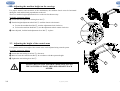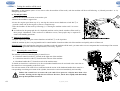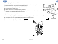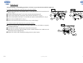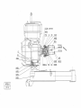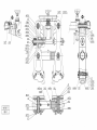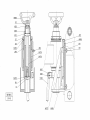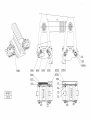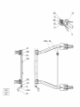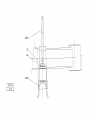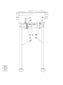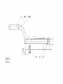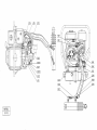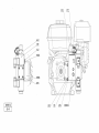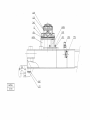
1
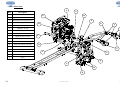
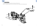
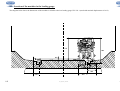
ANGLAIS
AP.3
HYDRAULIC MACHINE
FOR INSERTING AND
EXTRACTING PANDROL
"FAST CLIP" RAIL
ATTACHMENTS
Type
AP.3
GEISMAR, the quality choice !
You have just acquired a machine for laying and servicing railway lines. We thank you for choosing equipment developed and constructed by
GEISMAR / STUMEC, the fruit of over eighty years’ experience.
Every day since 1924, the GEISMAR Group has been investing in research and state-of-the-art construction to offer you the quality and
reliability so essential to the requirements of the world of railways.
This machine, built entirely in France from design through to delivery, has been subjected to continuous, extremely strict controls. Formed of
different mechanical elements assembled by highly qualified fitters, your machine has been tested, calibrated and controlled at every stage of its
production.
We are convinced that it will give you every satisfaction and are, of course, at your service to offer you any recommendations you may require
for its use or its maintenance.
We thank you for the confidence you have shown in us and, in the hope that we will remain one of your privileged partners, we would like to
confirm that we are totally available for any comments or recommendations you may care to make.
In accordance with our environmental safety policy, this manual has been printed on recycled paper.
INT_Gb_00002_070525.doc
CONTENTS
CHAPTER 1 – SAFETY
1.1
1.2
1.3
1.4
CHAPTER 5 – SERVICING / MAINTENANCE
Introduction
Safety and general usage recommendations
General safety instructions
Specific safety recommendations
1.4.1
1.4.2
1.4.3
5.1
5.1.1
5.1.2
5.1.3
5.1.4
5.1.5
5.1.6
5.1.7
5.1.8
Risks that may arise through use of the "AP.3"-type hydraulic
machine
Safety rules to be observed before and during use of the "AP.3"type hydraulic machine
Safety symbols and recommendations
5.2
CHAPTER 2 – DESCRIPTION OF THE MACHINE
2.1
2.2
2.3
2.4
2.5
General
Overview
Technical characteristics
Load distribution
Location of the machine in the loading gauge
6.1 Drawings and components
Placing the machine on the track
Adjusting the machine height on the carriage
Adjusting the height of the control arms
Tool set up
Inspecting the machine
Conditions of use
4.1.1
4.1.2
4.1.3
4.1.4
4.1.5
4.2
Operator work area
Starting and stopping the machine
Taking the machine off the track
Operating the control levers
Adjusting the insertion and extraction head
Storage
4.2.1
4.2.2
Preventive maintenance schedule
List of normally-wearing parts
CHAPTER 6 – CATALOGUE OF SPARE PARTS
CHAPTER 4 - USE
4.1
Engine
List of equipment and accessories essential for servicing
Carriage
Cleaning
Hydraulic circuit
Adjusting the main pressure limiter
Replacing tools
Greasing
Maintenance
5.2.1
5.2.2
CHAPTER 3 – INSTALLATION – STARTING
3.1
3.2
3.3
3.4
3.5
Servicing
General storage recommendations
Specific storage recommendations
AP3_Gb_00648_100210.doc
CHAPTER 1 – SAFETY
1.1 Foreword
The following set of rules has been drawn up to ensure the application of precautionary principles that help to preserve the safety of persons and property
when the machine is in use. Any failure to comply with these rules can have serious repercussions (bodily injury, etc.), and can even be fatal, so we must draw
your attention to the fact that all persons involved in the use, maintenance, storage or custody of the machine covered by the present manual must be familiar
with these rules.
Any users who cause an accident through failure to comply with these rules will be held personally responsible for the results of their actions.
1.2 Instructions for safety and general use
All persons using, servicing or repairing this equipment must have undergone the training, possess the skills, and have at their disposal the tools necessary to
carry out any such operations.
Before using the equipment, even in a maintenance context, it is necessary to read the corresponding instruction manual, together with its appendices, and the
safety rules in force in the workplace.
Comply carefully with the general safety instructions drawn up for the site by the person in charge of the site, especially if the work is carried out without
stopping or diverting traffic.
The equipment can only be used, serviced or repaired by competent personnel who have undergone thorough specialized training beforehand. The technical
documentation and the instructions are useful in completing the knowledge acquired during the training courses, but they can in no way replace theoretical and
practical qualifying training, provided in accordance with good professional practice.
If the operating company is not in a position to carry out the necessary training for its staff, at a satisfactory level, the GEISMAR/STUMEC Company is able
to provide advice concerning the training programme to be implemented.
The training must include an explanation of the various equipment functions, the instructions for use and maintenance, and the safety rules applicable, together
with practical exercises.
IMPORTANT! All persons using the machine must comply with the labour regulations in force
The GEISMAR/STUMEC Company cannot be held responsible for any modifications made without its
written approval, or for any assembly work not in conformity with its recommendations, especially in the
case of use of parts other than original manufacturer’s parts.
1.1
SECT_Gb_00003_070426.doc
1.2
1.3 General safety instructions
• The operator and the working environment
To avoid all risks of accident or injury, it is essential to wear:
- Sturdy, non-flammable clothing that is suitably close-fitting
- Strong, non-slip gloves
- Safety shoes
- Protective eyewear
- Safety helmet
- All other equipment necessary on the site or when using the machine
In the case of use of ear defenders, the safety instructions in force on the site must be complied with at all times.
Make sure that the machine vibrations do not lead to a loss of sensitivity in the hands. Adapt the working periods to the level of vibration caused by
the machine, which is shown within the framework of normal use.
Do not work with the machine if you are not sure that you can control it correctly. Do not start working with the machine until you are sure that you
can do so in full safety, for yourself (good conditions of visibility and lighting) and for other people (work calmly and carefully). Take care to ensure
you have a firm, stable footing; all unstable working positions must be prohibited.
The user must be in a physical and mental condition enabling work to be carried out without danger.
The work area must be free of all obstacles. The work area (and the surrounding areas) must be free of all flammable substances.
If anything does not seem clear to you, whether it concerns the machine or the work to be carried out, ask a qualified person for information. Do not
base your work on assumptions.
For underground use (tunnel or gallery), or in a closed area, make sure there is sufficient ventilation or extraction to avoid the risks generated by
inhaling exhaust gases or by their build-up.
This equipment must not be used in an explosive atmosphere.
Avoid working positions in which exhaust gases could come into contact with parts of the body, whether protected or not.
In a general way, take all necessary precautions to prevent flammable products from coming into contact with fire hazards.
The operator must ensure that no one else is within the working area. In particular, it is necessary to make sure that in the direction in which the
machine is travelling, no one can be hit. If someone is nonetheless in the path of the machine, the operator must stop and warn the person of his
passage.
When the machine is installed on the track, it must be handled only by the number of operators strictly necessary for its normal use.
As the overall size of the machines does not enable extinguishers to be carried on them, we strongly recommend placing extinguishers of an
appropriate type to deal with the fire hazards close to the machine.
The user must comply with all the regulatory environmental instructions applicable to the machine in use.
1.3
SECT_Gb_00004_090619.doc
1.3
• The operator and the machine
Before putting the machine into service each time, check that its condition and its operation are in compliance with the instructions.
In particular, make sure that the controls are free and in good working order, and that they are in the “stop” or “neutral” position. Never make any
modifications that could affect correct operation of the control systems.
All the protective elements must be kept carefully in place and in good condition.
Always keep the machine clean and remove any accumulated dust, especially if it could absorb flammable products.
Always move forwards when working.
When working, always hold the machine with both hands to ensure control at all times, and to be able to use it in full safety.
Never bring a machine close to a flame or a source of heat.
The machine must never be positioned close to hot or protruding elements that could damage some parts (tanks, exhaust, housings...).
Never move away from a machine while the engine is running, even when it is idling. Stop the engine immediately if the machine is not in use. After
stopping the engine, wait until all moving parts have come to a complete stop.
Work on the electrical installations on the machine can only be carried out by suitably qualified persons.
Read and make sure you fully understand all the signs placed on the machine, and always comply with all the instructions.
The signs placed on the machine include pictograms, manufacturer’s plates, and instruction labels. Make sure they are kept clean and replaced if
they have been damaged, or if they are missing or illegible. If one of these elements is on a part that is to be replaced, a new element must be present
on the replacement part. Please contact us on this subject.
When using a lifting device, the lifting operations of the machine must be done only using the lifting points indicated on the instruction manual.
When possible, the lifting of the machine is to be done only when the machine needs to be set in or out of the track. If the machine has to stay lifted
(for a maintenance operation for example), the hazardous area must be signaled/marked, so that no one can stay below the machine or walk close by.
THE MACHINE MUST NEVER BE USED FOR A PURPOSE OTHER THAN THAT FOR WHICH IT IS INTENDED
NEVER TOUCH A MOVING PART WITH A TOOL, OR WITH THE HAND, OR WITH ANY OTHER PART OF THE BODY
IT IS ESSENTIAL TO STOP THE ENGINE AND SET THE CONTROL TO THE STOP POSITION BEFORE CARRYING OUT :
-
1.3
ANY HANDLING WORK
ANY WORK TO CHANGE TOOLS OR SOCKETS
ANY WORK INVOLVING FUEL OR OIL (FILLING, TOPPING UP, CHECKING LEVELS, ETC.)
ANY REPAIR, MAINTENANCE OR CLEANING WORK
SECT_Gb_00005_110202.doc
1.3
• Using and handling fuel and oil
It is essential to stop the engine and set the control to the stop position before carrying out any work involving fuel (filling up, checking
the level, draining, etc.).
Always keep suitable extinguishers ready for use in all areas where fuel is handled (storage, filling up, etc.).
Always store fuel and oil in separate cans specially designed for the purpose and bearing the labels required by regulations. They must be stored in a
safe place, well away from all types of fire hazard.
Each time a machine is started up, and while it is running, make sure that there are no fuel leaks from any part of the machine. If a leak is suspected,
stop the engine immediately and do not restart the machine until the leak has been repaired.
Never carry out any work on a fuel tank or handle fuel to fill a tank, or for any other reason, in an area where there could be a fire hazard (such as a
burning cigarette, a blowtorch, sparks, etc.) or substances that are incandescent or at a high temperature (such as welding spatters, slag, clinker, etc.).
All such work must always be carried out outdoors or in a well-ventilated area.
Always turn all mobile phones off while filling a tank with fuel or handling fuel.
Carefully tighten the fuel filler cap each time, and check that no fuel leaks from it.
Always remove a filler cap slowly, to enable any internal pressure to be released without spraying any fuel out. Take special care if the surrounding
temperature is high.
When putting fuel in a machine that has heated up, never fill the tank completely. Do not put in more than three-quarters of the tank capacity.
If fuel starts to boil in the tank when putting fuel in a machine that has heated up, screw the cap on again immediately and leave the machine to cool
down.
Make sure the fuel used is suitable for the type of engine on the machine. See the user manual for the engine.
Do not inhale fuel vapour.
If it is necessary to drain the fuel tank, pour the fuel into a container designed for the purpose and bearing the labels required by regulations. Always
close them tightly, even if they only contain a small quantity. Never use a glass container.
Never use fuel for cleaning work. Use only non-flammable, non-toxic products that are harmless for the user, the equipment and environment.
If fuel has been spilt near the filling area for any reason, clean it up immediately. Clean straightaway any spillage of fuel on the skin. Make sure no
fuel has been spilt on your clothes; otherwise, change clothes immediately. Remove all rags or other materials used to wipe fuel, and store them in a
safe place well away from all sources of heat or combustion. Move the machine well clear of any spilt fuel before starting it up (at least 6 metres
away), and do not move any closer to the area while the engine is running.
IN CERTAIN CASES HANDLING OIL CAN GIVE RISE TO THE SAME TYPE OF RISKS AS HANDLING FUEL. IT IS THEN ESSENTIAL TO TAKE THE
SAME PRECAUTIONS WITH OIL AS THOSE SET OUT ABOVE FOR FUEL.
1.3
SECT_Gb_00006_110202.doc
1.3
•
Tools to be used on the machine
Use only the types of tools intended for normal use of the machine.
Measure the speed of all rotating tools at regular intervals.
Never use tools at speeds greater than the maximum speed for which they have been designed and approved.
Never use damaged tools or tools that have reached their maximum level of wear.
•
The engine on the machine
Never touch the hot parts of the engine, and especially the exhaust pipe. If it is necessary to work on the engine, wait until it has cooled down.
Check the engine rotation speed at regular intervals, and especially after fitting tools or reassembling the machine. Adjust if necessary.
Never exceed the speed shown in the technical specifications.
After starting with the choke, remember to return the choke to the normal running position.
Never wind the starter rope around your hand, and never release it suddenly.
If the machine does not operate correctly after the engine has been started, stop the engine and inform the head of maintenance.
•
For petrol engines, use only spark plugs whose tops are as shown in drawing 1 opposite. If the plug is fitted with a
screw top, make sure the top is fully tightened. After fitting the spark plug, make sure that the plug cap is in good
condition and that it stays firmly on the plug. Carefully check the fastening system to make sure that no sparks can
be formed.
Using trolleys (If applicable)
A machine designed to work on a trolley must not be used without the trolley. The trolley is thus an integral part of the machine. The machine and
the trolley must not be used separately.
Trolleys whose use is dedicated to a machine must never be used to transport equipment or personnel, or attached to a vehicle.
Before fitting the machine on its trolley, it must be placed correctly on the track to ensure that it can run freely. If it is on a sloping section of
track, make sure the trolley is kept immobile while the machine is being put on the track or taken off it.
Attention, the trolley takes up the full width of the track and can cause injuries to the legs if it hits someone.
1.3
SECT_Gb_00007_110202.doc
1.3
1.4 Specific safety recommendations
1.4.1 Risks that may arise through use of the "AP.3"-type hydraulic machine
The main risks for the user and those around that arise when using the "AP.3"-type hydraulic machine are:
Fire connected with fuel handling.
Sudden shifting of the machine if it is poorly regulated, which may injure the operator or someone nearby.
A foot or other part of the body catching in the machine’s moving parts.
Clips being thrown off during extraction.
In addition to the use of the Personal Protective Equipment described in §1.3 "General safety instructions” / sub § “The operator and his environment", we
recommend use of hearing protection. Nonetheless, refer to the applicable rail regulations governing the work site to determine if this can be used or not.
1.4.2 Safety rules to be observed before and during use of the "AP.3"-type hydraulic machine
All personnel using this equipment must wear the clothing listed in paragraph §1.3 "General safety instructions / The operator and his environment."
Before starting the machine, make sure it is in good condition and all machine components are properly attached. Never modify the machine.
Before removing the machine from the tracks, or if it must be moved between two series of work, shut the engine off.
1.4
AP3_Gb_00649_091208.doc
1.4
1.4.3 Safety symbols and recommendations
The safety pictograms and recommendations must be present on the section grinder at the indicated location.
If one of them is missing or has deteriorated, another must be ordered immediately and installed in its place.
If a component bearing a label has been replaced, make sure a new label is properly placed on the replacement part.
Reference:N° 12528 (yellow background)
Location: Stuck on.
Reference: N° 55128 (red background)
Location: Stuck on the machine’s
insertion/extraction head.
Reference: N° 12569 (blue
background)
Location: Stuck on the lifting
eye bolt.
Reference: N°12654(yellow background)
Location: Stuck on the machine’s hydraulic
tank
Reference : N° HUU (yellow background)
Emplacement : Stuck on the machine’s
electrical cabinet.
1.4
AP3_Gb_00650_091208.doc
1.4
CHAPTER 2 – DESCRIPTION OF THE MACHINE
2.1 General
Manufacturer:
SOCIETE TURRIPINOISE DE MECANIQUE
Route d’Italie
38110 LA TOUR DU PIN
Description of equipment:
Hydraulic machine for inserting and extracting Pandrol
"Fast Clip" rail attachments
Type:
AP.3
The "AP.3" type hydraulic machine is designed to insert and extract Pandrol "fastclip" rail attachments on all types of rail.
The user-friendly work station, operating speed, mass and very compact size of the machine provides particularly high efficiency while reducing the
operator fatigue. Its exceptional performance, durability and lightness provide the operator with the convenience of optimum usage. The extraction
force has been defined so that the machine can carry out all types of on-site work.
The machine is very simple to use, with few adjustments required, and needs very little maintenance. It is operated effortlessly via control handles
located on arms that can be adjusted for operator comfort. The head comes with insertion tools acting on the rear clips buckles and extraction tools
acting on the front clip buckle.
The latching system allows for rapid changeover from the insertion position to the extraction position, and vice versa.
The machine has been designed for use on a traverse.
2.1
AP3_Gb_00651_091208.doc
2.1
2.2 Overview
F
Ref.
Description
A
Support foot
B
Electrical cabinet
C
Retractable carrying handle (x2)
D
Engine
E
Hydraulic pump
F
Hydraulic oil tank
G
Lifting eye bolt
H
Chassis
J
Height adjustment wheel
K
Remote engine shutdown button
L
Arm (x2)
M
Dead man handles (optional)
N
Control levers
P
Spotlights
Q
Insertion tool x 2
R
Extraction tool x 2
S
Head
G
H
E
J
K
D
L
M
C
B
N
A
P
Q
S
R
Q
2.2
AP3_Gb_00652_100104.doc
2.2
2.3 Technical characteristics
ENGINE TYPE (4 stroke)
HONDA GX200 **
Machine dimensions
Length / width / height (arms folded in)………….…....
mm
Auto-braked carriage dimensions
Length / width / height…………………………….…...
mm
Weights
Machine (no load) ……………….…………………….
Machine (in working order)……………………………
Carriage………………………………………………..
kg
kg
kg
110
113
37
dB (A)
dB (A)
84 (±2)
100 (±2)
ms -2
4.97 (left arm) / 4.64 (right arm) (±2%)
Engine emissions of polluting gases……………...
kW
liter
l/h
……
…….
g/kW.h
4.1 (= 5.5hp) at 3600 rpm *
3.1
1.7
Unleaded petrol (at least 91 octane)
Automatic return cable starting
CO = 313 / NOx = 3.8 (about)
Machine
Engine rotation speed (no load)……… .………….......
Hydraulic circuit pressure ….……..……………..........
rpm
bar
1065 / 570 / 1030
1845 / 595 / 385
Noise
Acoustic pressure level (Laeq) (1)……………….……
(2)
Acoustic power level (Lwa ) ………………….……..
Vibrations
Level of vibration (Aeq) (3)….………….……………..
Engine
Power….……………….………………………………
Fuel tank capacity……………………….……………..
Fuel consumption (at 3600 rpms)…………...………....
Fuel…………………………………………………….
Starting…………………………………………….......
3600
210
* The motor power stated in this document corresponds to the produced net power tested on a standard motor and measured according to SAE J1349 at a given motor speed. This power value can be different on other standard motors. The net power
produced by the motor on the machine can vary for a variety of reasons, such as the motor speed for the specific application, the environmental conditions, etc.
** AP. 3 Honda GX200 approved by the SNCF under the number: DPI 09111
(1)
2.3
Measurements done according to NF EN ISO 11204 while machine working. (2) Measurements done according to NF EN ISO 3746 while machine working. (3) Measurements done according to NF EN ISO 5349 while machine working.
AP3_Gb_00653_091208.doc
2.3
2.4 Load distribution
The diagram below defines the load distribution in percentage of machine weight.
Refer to §3.3 “Placing the machine on the track” to determine the number of people required for handling operations.
47 %
53 %
2.4
AP3_Gb_00654_091208.doc
2.4
2.5 Location of the machine in the loading gauge
The diagram below shows the dimensions of the machine in relation to the low loading gauge UIC 505-1 (track with nominal displacement of 1435).
737
842
40
269
170
2.5
269
AP3_Gb_00655_100104.doc
2.5
CHAPTER 3 – INSTALLATION – STARTING
3.1 Placing the machine on the track
The “AP.3"-type hydraulic machine can be set up, on or close to a railway, using a crane or any other hoisting device with force greater than the
mass of the machine as defined in §2.3 "Technical Characteristics," using the lifting eye bolt Ref.⑥.
The machine can also be manually set up by means of the 2 carrying handles Ref.⑤ and the 2 control arms Ref.⑦. This set up must be carried out by three
agents at least. Nonetheless, if the work area is difficult to access, more people may be required to ensure safe handling operations.
To place the machine on the track, proceed as follows:
➊ Set up the traverse Ref.① on the track (if the ground slopes, plan on one person to keep it
immobile).
➋ Once the traverser is on the track, position the slider Ref.② on the side of the track where
the machine will be set up and be sure to block it by lowering the lever Ref.③.
6
5
YOU MUST USE AN OFFSET HIGH KNUCKLE
ON THE TRAVERSER (REF 202V)
➌ Take the 2 carrying handles Ref.⑤ out and put the hydraulic machine in place on the
traverser manually. If the set it up is carried out using a crane, it is not necessary to take out
the 2 retractable carrying handles.
➍ Raise the support foot Ref.④ so it doesn’t interfere with the movement of the hydraulic
machine. Depending on the configuration of the track, the support foot may rest against the
carriage. In this case, put the extraction tools (Cf. §3.4 "Tool set up") in the raised position
so as to lower the head of the hydraulic machine and allow the support foot to pass above the
carriage.
NOTE: If no hoisting device is available on the work-site, unfold the two carrying arms
Ref.⑤ and position the machine on the track.
4
7
3
2
1
If the traverser is not equipped with an automatic braking device (optional), it must be immobilised (wedged) once positioned on the track. This is to
avoid the traverser moving on its own, and in order to prevent injury in the event of collision.
THE MACHINE MUST BE PLACED ON AND TAKEN OFF THE TRACK
WITH ENGINE OFF
3.1
AP3_Gb_00656_091208.doc
3.1
3.2 Adjusting the machine height on the carriage
For proper insertion and extraction of the attachments, the machine chassis must be horizontal
during the work and the head perpendicular to the rail.
There is a machine height adjustment device on the cart for this necessity.
To do this, proceed as follows:
2
➊ Loosen the head adjustment locking lever Ref.①.
➋ Turn the height adjustment wheel Ref.② until the chassis is horizontal.
3
To raise the machine head Ref.③, turn the adjustment wheel clockwise.
To lower the machine head Ref.③, turn the adjustment wheel counter clockwise.
➌ Once adjusted, lock the head adjustment lever Ref.① in place.
1
3.3 Adjusting the height of the control arms
For operator comfort, the height of the control arms can be adjusted using a notch system.
To do this, proceed as follows:
➊ Loosen the arm locking lever Ref.① a few turns.
➋ Raise or lower the control arms Ref.② in accordance with the operator height.
2
➌ Tighten the arm locking lever Ref.①.
1
ALWAYS BLOCK THE MACHINE ARMS IN PLACE SO
THE NOTCHES ON EACH ARM ARE OPPOSITE EACH
OTHER
3.2
AP3_Gb_00657_091208.doc
3.3
3.4 Tool set up
All tool mounting or dismantling operations, of whatever type, must be done with the engine off.
To switch from insertion to extraction mode, and back:
➊ Pull the locking latch Ref.③ (as indicated in Fig. 4) that controls the automatic unlocking of the tool.
➋ Manually raise the other tool until the latch automatically locks it in place.
Fig. 4
3
Always carry out the same operations on every part of the machine head.
It is not necessary to withdraw the insertion tools for extraction
work, and vice versa.
You cannot able lock the insertion and extraction tools
simultaneously.
INSERTION WORK
3.4
EXTRACTION WORK
AP3_Gb_00658_091208.doc
3.4
3.5 Inspecting the machine
Each machine component must be inspected by a qualified person prior to commissioning in order to detect any defects. This is mainly a visual and operational
inspection.
The inspection phase ensures the different components are in good condition and have not been damaged during transport or storage.
• General inspection of the machine
Make sure all components are properly tightened and there are no oil and fuel leaks (engine and head).
• Checking the mechanical-welded assemblies (this inspection takes place with the engine off)
Visually check that there are no external defects, deformations, superficial cracks, wear or marks of corrosion.
• Checking levels (this inspection takes place with the engine off)
Fuel level: Check the fuel level and if necessary fill it up (
: Refer to §1.3 “General safety instructions” / sub-§: "Use and handling of fuel" before any
action).
Hydraulic oil level: Check the oil level and top it up if necessary (refer to §1.3 "General safety instructions").
Engine oil level: Use the gauge to check the motor oil level, and top it up if necessary. It must come up to just below the maximum gauge mark, and must not
go over it (see engine guide).
• Checking the safety devices
Start the engine (
: refer to §4.1.2 "Starting and stopping the engine") and make sure the safety equipment is working properly (remote engine shutdown).
• Checking the operation
Make sure the machine height adjustment device functioning properly: This means that when they are operating, the components must move as smoothly as
possible, without sticking.
IN THE EVENT AN ANOMALY SHOULD BE FOUND DURING THIS INSPECTION OR DURING USE, THE MACHINE MUST BE RESTORED TO FULL
COMPLIANCE BY QUALIFIED PERSONNEL OR BY THE MANUFACTURER PRIOR TO RE-USE.
3.5
AP3_Gb_00659_091208.doc
3.5
CHAPTER 4 – USE
≈ 3040mm
4.1 Conditions of use
WORK AREA
4.1.1 Operator work area
The operator work area is situated within the two vertical limits (between the two
rails), defined by the UIC 505-1 loading gauge (Cf §2.4 "Location of the machine in
the loading gauge").
During work, the operator must always be between the two arms of the machine in
order to maintain complete control of it.
The operator must always be positioned in the middle of the track (working with one foot on each side of the rail). If the operator is situated between the two
arms of the machine and the machine head is positioned on the attachments, the operator will never be able to move outside the two vertical limits defined by
loading gauge UIC 505-1.
4.1.2 Starting and stopping the machine
1
Refer to the engine manufacturer’s guide to determine the location of the components to activate
when starting and stopping.
The engine must only be started and stopped (under normal conditions of use) after the machine
head has finished the insertion or extraction cycle.
Starting:
• Make sure the remote shutdown control Ref.① is on position 1.
• Start the engine, let it run on idle for a short time until the engine speed stabilises and the
engine temperature rises.
• Once the engine is hot, increase the engine speed by moving the engine gas control to
maximum (factory set).
Stopping the machine:
• Lower the engine speed by moving the gas control to the slow position (or low speed).
• Stop the engine by pushing in the remote shutdown switch Ref.① to one of the two 0 positions.
ONLY START THE ENGINE WHEN THE MACHINE IS IN PLACE ON THE CARRIAGE, THE CARRIAGE
IN NORMAL POSITION ON THE TRACK, THE TOOLS CORRECTLY INSTALLED AND BLOCKED IN PLACE.
4.1
AP3_Gb_00660_091208.doc
4.1
4.1.3 Taking the machine off the track
Depending on the situation (more or less time to take the machine off the track), take the machine off the track following “a) Normal procedure” or “b)
Emergency procedure”.
a) Normal procedure
1
• Wait for the end of the insertion or extraction cycle.
• Remove the machine’s support foot.
• Lower the engine speed then stop it by moving the remote motor shutdown switch Ref.① to
position 0, then wait for the engine to come to a complete stop.
• Take the machine off the track by following §3.3 “Placing the machine on the track” in reverse
order.
As indicated in the paragraph, the AP.3 hydraulic machine can be placed on/taken off the track by
three people. Nonetheless, if the work area is difficult to access, more people may be required to
ensure safe handling operations.
b) Emergency procedure
• Stop the engine by pushing the remote shutdown switch Ref.① to the 0 position.
• Hold the machine by the 2 carrying handles and 2 control handles located on either side of the machine and quickly take it off the track.
IMPORTANT: After applying the emergency procedure to take the machine off the track, you must make sure no component has been damaged. Do not start
the machine up again until it has been inspected and, if necessary, repaired.
4.1.4 Operating the control levers
3
The machine cycles are controlled using 2 control levers:
1 insertion control lever Ref.① located on the right arm of the machine.
1 extraction control lever Ref.② located on the left arm of the machine.
2 deadman handles Ref.③ located on each of the machine arms.
To launch an insertion or extraction cycle, the two deadman handles must be activated at the same time as
the control lever corresponding to the work cycle.
For each movement of the control lever combined with the action of the deadman handles there must be a
corresponding correlating movement of the cylinder, that must be carried out immediately and smoothly.
Release the control lever as soon as the cycle ends. Never press on a clip for more than a few
seconds. Pressing on the clip does not increase the force, but it does rapidly and abnormally
heat up the hydraulic circuit oil.
4.1
AP3_Gb_00684_100104.doc
1
2
4.1
4.1.5 Adjusting the insertion and extraction head
In order to facilitate the adjustability of the stops, the rings Ref.①
① and Ref.②
② must not be in contact with the head levers. To do this, press the
appropriate control levers while activating the 2 deadman handles (Cf §4.1.4: "Operating the control levers"), to bring the head levers to any
position before stopping the engine.
Stop the motor to avoid all risk of bodily harm due to being caught up in the moving parts.
Adjusting the machine for work in "INSERTION"
1
Adjusting the exterior lugs
1. Put the insertion tools in position (Cf §3.4: "Tool set up").
2. Place the machine on one of the fastenings to be inserted.
3. The exterior adjustment rings Ref.② limit the opening of the head. Regulate the exterior adjustment rings Ref.②
so as to leave sufficient clearance between the clips and the insertion tools. There must be enough clearance to
properly position the head, but not too much to optimise the machine efficiency.
If the exterior adjustment rings Ref.① are unscrewed, there will be a bigger gap between the tools.
If the interior adjustment rings Ref.① are screwed in, the gap will be smaller.
4. Start the engine.
5. Activate the extraction control lever (and the 2 deadman handles) in order to bring the levers into contact with the lugs
Ref.②.
6. Visually check to see if there is enough clearance between the clips and the tools:
If yes: - The adjustment is finished.
If no: - Stop the engine and repeat steps 2, 3 and 4.
2
Contact area
Adjusting the interior lugs
1. The interior adjustment rings Ref.① limit the closing of the head and the insertion of the clips. The clips must not be in too far, otherwise they may damage
the fastening’s plastic insulators.
If the interior adjustment rings Ref.① are unscrewed, there will be a bigger gap between the tools and the clips won’t be in as far.
If the interior adjustment rings Ref.① are screwed in, there will be a smaller gap between the tools and the clips will be in deeper.
2. Start the engine, place the machine on one of the fastenings to be inserted.
3. Activate the insertion control lever (and the 2 deadman handles) and visually make sure the clip has not damaged the plastic insulator. If this is the case,
immediately release the insertion control lever and carry out a new adjustment.
4. Visually check to see if the clip is in deeply enough:
If yes: - The adjustment is finished.
If no: - Repeat steps 1, 2 and 3.
Adjusting the machine for work in "EXTRACTION"
Fix the lever contact area against the FASTCLIP insert during extraction (see diagram above).
The extraction tools on the head do not allow full extraction of the clips. If from time to time you want to carry out a full extraction, use total
extraction lugs.
4.1
AP3_Gb_00685_100104.doc
4.1
Adjusting the exterior lugs
1. Unscrew the exterior adjustment rings Ref.② as far as possible. They are not used when extracting clips. These are the tools that define the distance
between clips.
The clips can never be completely removed from the attachments using these tools.
Adjusting the interior lugs
1. Put the extraction tools in position (Cf §3.4: "Tool set up").
1
2. Start the engine, place the machine on one of the fastenings to be extracted.
3. Activate the insertion control lever; when the head has finished closing, release the control lever and shut off the
engine to avoid all risk of bodily harm due to being caught up in the moving parts. Regulate the exterior
adjustment rings Ref.② so as to leave sufficient play between the clips and the extraction tools. There must be
enough play to properly position the head, but not too much to optimize the machine efficiency.
If the interior adjustment rings Ref.① are unscrewed, there will be a bigger gap between the tools and the
tools will be closer to the clips.
If the interior adjustment rings Ref.① are screwed in, there will be a smaller gap between the tools and the
tools will be farther from the clips.
4. Start the engine.
5. Activate the insertion control lever in order to bring the lever into contact with the lugs Ref.①.
6. Visually check to see if there is enough play between the clips and the tools:
If yes: - The adjustment is finished.
If no: - Stop the engine and repeat steps 2, 3, 4 and 5.
2
3
Using the full extraction lugs
The extraction tools do not allow full extraction of the clips. You must use full extraction lugs Ref.③.
The interior and exterior lugs for extraction work must never be modified.
To extract the clips from the attachments, proceed as follows:
1. Extract the clips as described previously. The clips are still fixed to the attachments.
2. Clear the machine in order to be able to position the full extraction lugs safely.
3. Put the full extraction lugs in place Ref.③ on the clips.
4. Activate the insertion control lever to close the head.
5. Place the machine above the clips to be extracted.
6. Activate the extraction control lever until the 2 clips have been fully extracted.
Position the full extraction lugs in the middle of the main machine support when using the latter.
Make sure you do not leave the full extraction lugs on the machine during transport in order not to lose them.
4.1
AP3_Gb_00663_091208.doc
4.1
4.2 Storage
4.2.1 General storage recommendations
During periods where the equipment is not in use, it is indispensable to store it properly in order to keep it in good working order. Poorly-stocked equipment
may deteriorate when recommissioned. Il is also important for the personnel responsible for storage operations to take great care during storage, and to
carefully follow the recommendations.
Storage protection system
The choice of storage protection systems depends on 2 main factors:
- the length of time it will be stored
- the storage conditions: "unprotected" storage (exposure to bad weather) and "protected" storage (building, closed hangar, open hangar, canopy, etc.)
Equipment must be broken in before being stored. Measures must be taken to ensure ease of access around the equipment for servicing purposes.
Storage sites
In general, premises for storing equipment should provide as good protection as possible against:
- dust, exhaust emissions, humidity
- direct sunlight
- rapid temperature changes
Storage procedures
The state of the equipment when recommissioned after storage depends on the way it was prepared and protected before storage:
- cleaning the equipment (when cleaning, protect the moving parts with grease)
- technical inspections to check for anomalies
4.2.2 Specific storage recommendations
If work should be halted for more than one week:
- Empty and clean the fuel tank in a well-ventilated area.
- Eliminate the fuel in compliance with the regulations governing the protection of the environment.
- Run the engine until the carburettor is completely empty.
4.2
AP3_Gb_00664_091208.doc
4.2
CHAPTER 5 – SERVICING / MAINTENANCE
5.1 Servicing
Proper training, skills and tools are required to correctly use, maintain and repair this material.
This equipment may only be serviced and repaired by skilled personnel with a thorough knowledge of general mechanics.
Before carrying out any servicing or repair operation, stop the engine (leave the control in the stop position) and wait for it to cool down.
Safety when using this machine depends largely on proper servicing.
Waste resulting from servicing and maintenance operations (fluids, filters, used cloths, etc.) must be processed in accordance with applicable regulations
governing the protection of the environment.
Any part that is worn, damaged or missing must be changed or repaired immediately, whenever there is a risk in terms of safety.
5.1.1 Engine
•
Refer strictly to the engine guide provided with the machine.
5.1.2 List of equipment and accessories essential for servicing
The following tooling is required for carrying out all the servicing and maintenance operations correctly:
Work tooling (provided with the machine)
17 open-ended spanner (Ref. FJM)
19 open-ended spanner (Ref. FRR)
30 open-ended spanner (Ref. FYK)
17 elbow pipe wrench (Ref. FZG)
Spark plug spanner (Ref. GGK)
Maintenance and servicing tooling (not provided with the machine)
13 open-ended spanner
4, 5 and 6 spanners
This list of tooling does not exclude the need for normal necessary equipment such as: cloths, brushes, grease, etc.
5.1
AP3_Gb_00665_091208.doc
5.1
5.1.3 Carriage
2
- Periodically lubricate the pivot between the knuckle Ref.② and the housing in the slider
Ref.③.
3
1
- Make sure the knuckle lugs Ref.② are not distorted or broken. They must be absolutely
straight.
- Make sure the locking lever of the slider Ref.① firmly locks it in place on the carriage.
5.1.4 Cleaning
Make sure that the machine is kept as clean as possible. Care in cleaning the machine will lead to longer service life and
improved performance.
Clean the machine carefully with a clean cloth or an airgun, taking special care to remove all dirt that has accumulated on it, especially close to any moving
parts. As a precautionary measure, always wear gloves to avoid injury or burning of hands. Do not use fuel for cleaning operations. Only use non-inflammable,
non-toxic products that are inoffensive for both the operator and the machine.
5.1.5 Hydraulic circuit
- Checking the level: The indicator Ref.① located on the side of the hydraulic tank lets you check the inside oil level. With the machine perfectly horizontal,
the oil level must be between the zone defined in Fig. 1 (minimum recommended level) and the upper part of the level indicator Ref.①
(maximum level).
LEVEL
Fig
Maximum level
Minimum level
1
5.1
AP3_Gb_00666_091208.doc
5.1
- Filling up:
Fill it up via the filter Ref.② by unscrewing the plug Ref.①
using a screwdriver. Be careful with the spring Ref.⑤ and
be sure you don’t damage the O-ring Ref.④ (Fig.2).
2
1
Only use hydraulic oil.
For example:
TOTAL: Equivis 246
ESSO: Teresso 43
MOBIL: Mobiloil DTE light
SHELL: Tellus T 27
- Oil change: The tank is drained via the plug Ref.③ situated beneath the tank (Fig.1).
- Cleaning the oil filter: After 50 hours of operation, then every 500 hours, clean the oil filter (Fig.1).
Work in a clean environment when cleaning the oil filter.
3
Fig. 1
First remove the plug Ref.①, spring Ref.⑤ and O-ring Ref.④.
To dismantle the filter, proceed as follows:
Carefully remove the filter Ref.② from its housing, wash it in a non-flammable non-toxic solvent, let it
drain and dry it thoroughly.
Put back all of the components by carrying out the operations in the reverse order.
1
4
To replace the filter, proceed as follows:
Remove the worn filter from its housing.
Make sure the filter body Ref.⑦ and spacer Ref.⑥ are clean, and clean them if necessary.
Replace the worn filter with a new one.
5
2
Fit the oil filter in the right direction. The filter shoulder must be positioned upwards
as indicated in Fig. 2.
7
6
Fig. 2
5.1
AP3_Gb_00667_091208.doc
5.1
5.1.6 Adjusting the main pressure limiter
4
The main pressure limiter is adjusted in the factory, and theoretically should not require any later adjustment.
Nevertheless, if necessary, it can be adjusted by proceeding as follows:
3
➊ Disconnect the 2 couplers Ref.① of the hydraulic block Ref.②.
2
➋ Fit a pressure gauge to the plug Ref.③.
5
➌ Start the engine (Cf §4.1.2 "Starting and stopping the engine).
1
➍ Manually activate the hydraulic distributor Ref.⑤ on side "a" (to do this insert any metal tool of Ø 3 max in the
central hole of the adjustment handful) as indicated in Fig.1.
Side “a”
Adjust the pressure by proceeding as follows:
➊ Remove the cap Ref.④ (Fig.1), then unscrew the locknut Ref.⑦ (19 spanner) and adjust the pressure while screwing
on or unscrewing the adjustment screw Ref.⑥ (flat-head screwdriver) (Fig.2).
➋ Tightening the screw Ref.⑥ increases the pressure, loosening it decreases the pressure.
Fig. 1
➌ Proceed by small successive adjustments until you obtain 200 bars.
Tool insertion
➍ Screw the locknut Ref.⑦ back in, then refit the cap Ref.④
6
7
Fig. 2
5.1
AP3_Gb_00668_091208.doc
5.1
5.1.7 Replacing tools
All tool mounting or dismantling operations, of whatever type, must be done with the engine off.
To change the insertion and extraction tools, proceed as follows:
Fig. 2
Fig. 1
➊ Remove the pins Ref.② and washers Ref.① to free the insertion and extraction tools
Ref.④ (Fig.1).
➋ Pull the locking latches Ref.③ to free the insertion and extraction tools.
➌ Unscrew the 4 bolts Ref.⑤and remove the protective plate Ref.⑥ (Fig.2).
➍ Unscrew the headless bolts Ref.⑦ to lock the tool in place on the shaft Ref.⑧ (Fig.3).
➎ Remove the tool shafts Ref.⑧ (Fig.3).
➏ Remove the insertion and extraction tools to carry out the change.
4
3
1
5
6
2
1
To refit the insertion and extraction tools, proceed as follows:
➊ Set up the insertion and extraction tools while making sure the tool shafts are properly
positioned in the slots.
➋ First insert the washers then the pins to keep the tools in place.
➌ Block the tool and tool shaft assembly in place with the headless bolt. Make sure the
shaft and tool turn simultaneously.
➍ Replace the 4 bolts while keeping the spring protective plate in place.
Fig. 3
8
7
5.1
AP3_Gb_00669_091208.doc
5.1
5.1.8 Greasing
Each week, put some grease in the greaser Ref.Ⓖ (Fig.1) located on the frame of the machine.
Use the one of the greases recommended below:
- TOTAL
MULTIS 2
- KLÜBER
NATOSBIN B 1600 EP
or any other grease satisfying the standard DIN 51 354 or ISO.L.XBBFB.00 (lubricate slipping by rang 00 for gears strongly charged. Temperature of use – 20°C
à + 120 ° C).
Make sure that the machine height adjustment device is always greased and oiled, particularly the pivot axle Ref.①
(Fig.2).
Fig. 2
Lubricate weekly the locking latch axle of tools Ref.② (fig.3) and the travels thrust axle Ref.③ (fig.4).
1
Fig. 4
3
2
Fig. 1
G
Fig. 3
5.1
AP3_Gb_00688_100210.doc
5.1
5.2 Maintenance
5.2.1 Preventive maintenance schedule
FREQUENCY
COMPONENTS
TYPE OF OPERATION
Entire machine
Inspecting the machine
Entire machine
Perform
general
cleaning with a clean
cloth or blow nozzle to
remove dirt from the
machine
Lubrication
Grease / Oil
Hydraulic circuit
Check
Before
each use
After
each use
Every
week
X
Every
50
hours
Every
100
hours
When there are
obvious signs
of wear or
malfunction
See
Chap.3 - § 5
X
Chap.5 §1.3
X
X
Chap.5 §1.8
Chap.5 §1.5
NOTE: These recommendations are not exhaustive. Treating a machine with care and properly organising regular preventative maintenance can only
extend a machine’s lifespan.
5.2
AP3_Gb_00670_100210.doc
5.2
5.2.2 List of normal wear parts (this list does not include motor parts)
This is a list of normal wear parts on the machine together with the conditions under which they should be replaced.
Nevertheless, any part that is worn, damaged or missing must be changed or repaired immediately, whenever there is a risk in terms of safety.
5.2
Description
Ref.
No.
Replacement conditions
Engine shutdown switch
HBD
1
Broken or malfunctioning switch
Insertion tools
64763
2
Extraction tools
64764
2
Full extraction lugs
64803
2
Closed rubber handle Ø27
LZ
2
AP3_Gb_00671_091208.doc
Wear or deterioration
5.2
CHAPTER 6 – SPARE PARTS CATALOG
6.1 Drawings and parts lists
6.1
CH6_Gb_00031_070529.doc
6.1
IMPORTANT
Afin que votre commande de pièces de rechange soit suivie d’une livraison prompte
et correcte, bien indiquer :
- Le rep., le nombre et la désignation des pièces de rechange
- Le type et le n° de série de la machine (plaque sur le châssis)
*********************************************************************
IMPORTANT
To ensure that you are delivered promptly and correctly after placing an order for
spare parts please state:
- the Reference, number and description of the spare parts
- the type and serial number of the machine (to locate this number, look at the plate on the chassis)
**********************************************************************
WICHTIG
Um uns eine schnelle und fehlerlose Erledigung lhres Ersatzteil-Auftrages zu erlauben,
bitten wir Sie um folgende Angaben :
- Seriennummer und Baujahr der maschine
- Benennung und Bestellnummer der Ersatzeile
CDE_Gb_00033_070529.doc