1
DBBC installation and tests
at the 40 m radiotelescope
P. de Vicente, R. Bolaño, C. Almendros
Informe Técnico IT-OAN 2011-08
1
Revision history
Version
1.0
Date
15-09-2011
Author
P. de Vicente
Updates
First version (A draft yet)
CONTENTS
2
Contents
1
Introduction
3
2
The DBBC
3
3
Cabling with external equipment
5
4
Basic installation. Windows setup
4.1 Starting the server . . . . . . . . . . . . . . . . . . . . . . . . . . . . . . . . .
4.2 First tests: errors . . . . . . . . . . . . . . . . . . . . . . . . . . . . . . . . .
6
7
12
5
Hardware updates
5.1 The FILA board . . . . . . . . . . . . . . . . . . . . . . . . . . . . . . . . . .
5.2 The PC block . . . . . . . . . . . . . . . . . . . . . . . . . . . . . . . . . . .
5.3 The main computer board . . . . . . . . . . . . . . . . . . . . . . . . . . . . .
12
12
14
14
6
Calibration procedure
15
7
Connection to the Field System
7.1 Installation . . . . . . . . . . . . . . . . . . . . . . . . . . . . . . . . . . . .
7.2 Test and usage . . . . . . . . . . . . . . . . . . . . . . . . . . . . . . . . . . .
7.3 Procedure modification . . . . . . . . . . . . . . . . . . . . . . . . . . . . . .
17
18
19
21
1
1
INTRODUCTION
3
Introduction
The OAN purchased a DBBC from HAT-Lab in 2009. The backend was installed and tested
at the end of 2010 and beginning of 2011, but not used in real VLBI observations yet. In July
2011, the DBBC had a hardware problem and a board had to be replaced. This report is a
summary of the installation operations and tests performed in the DBBC.
2
The DBBC
The DBBC purchased from HAT-Lab is the first version released by the company and it is
composed of several elements. All of them are housed in a standard box 8U height and 500 mm
deep to be inserted in a 19” rack. The box is composed of two basic sets: the electronics and an
industrial PC. There are three power supplies for both elements. A big fan keeps the air flowing
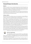
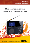
inside. All external connections are at the rear of the equipment (see Fig. 2). The front only
displays the LEDs from some of the cards (the CORE2 boards) and these lights can be used to
diagnose the equipment.
The following modules compose the electronics set of the DBBC (The user’s manual contains the complete documentation):
• A conditioning module which adjusts the correct power level of the signal, uses a 500
MHz filter in the 10-1000 MHz band, measures the total power and allows to select one
input from 4.
• A timing module which generates time and frequency signals from an external 10 MHz
(0 dBm) signal and 1 PPS.
• Two FiLA cards at the beginning and end of the Analog to Digital Boards and CORE2
boards. The first card is used as an interface for the input/output of data, commands and 1
PPS. The second one generates the VSI format and allows to generate an analog monitor
signal from a selected channel.
• Four ADB modules which convert the signal from analog to digital. The sampler clock
works at 1024 MHz. The instantaneous bandwidth in real mode is 750 MHz. The new
DBBC version (2) allowes a wider instantaneous bandwidth (1.1 GHz).
• Four CORE2 boards connected to the four ADB1 modules. Each CORE2 board converts
the signal to baseband and it is equivalent to 4 old standard BBCs. Possible bandwidths
are 0.25, 0.5, 1, 2, 4, 8, 16 and 32 MHz. The frequency of the band is selectable between
10 and 2048 MHz. The LEDs in front of each board have a meaning which can be found
in the Users’ manual.
The PC set is composed of a main computer board, a board with PCI connectors which acts
as a bus, two PCI cards from Adlink (PCI 7200 and PCI 911HR) used to connect to the IF
section and the FPGA registers and a Xilinx USB device used to program the FPGA cards via
a ’JTAG’ interface. The USB Xilinx is connected to the main board through an USB cable to
the USB port. The clock timing module is programmed via the PC parallel port to produce the
2
THE DBBC
4
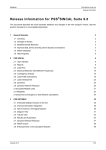
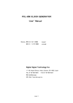
Figure 1: Front of the DBBC with the cover (four COREs activated and configured) and without it (two
COREs activated and configured).
Figure 2: Rear side of the DBBC. Only one IF cable was being used.
3
CABLING WITH EXTERNAL EQUIPMENT
5
standard 1024 clock required by the electronics. The main computer board has a 4 or 8 flash
card which contains the operative system, the firmware and software required to manage the
DBBC.
3
Cabling with external equipment
Below we describe the cabling required to connect the DBBC to make it work. Currenty 4 IF
500-1000 MHz signals from the receiver cabin are injected into the VLBA4 terminal. Two of
these signals are taken out again from the front connectors of the IF distributors and injected
in the preprocessor unit of the FFTS. These two signals are copied inside the preprocessor unit
and sent to the DBBC. The other two should be directly taken from the monitor connector of
the VLBA IF distributor.
In the future, when the VLBA4 terminal is no longer used, we will use a switchboard to
send the signals to the different backend units.
• Two cables from the IF are connected to the DBBC. The signal should be -30 dBm approximately in 500 MHz and be flat with a few dB slope at most. The inputs currently
used are A1 and B1. In astronomy it is usual to use one frequency band and two pols.
Geodetic observations use 3 bands and hence it will require three inputs: A1, B1 and C1.
• A 10 MHz signal from the Quarztlock distributor is used to provide the reference.
• 1 PPS from the VLBA terminal is used for synchronization. This signal is extracted from
the ”Frame Sync” connector at the front of the VSI4 module. It is a square signal 4 V
amplitude, 200 ms wide.
• The output VSI cable is connected to the input connector of the Mark5B. Since the cable
is rather short, the DBBC has been placed immediately beneath the Mark5B.
• The USB cable that comes out of the back part of the DBBC is connected to the USB port
of the main card. This cable is connected to the USB programmer which allows to talk
with the electronics inside the DBBC.
• The PS2 mouse and keyboard cables are connected to a dual PS2 cable, which is attached
to the PS2 main board connector. This is rather convenient since we use a KVM device:
a common screen, pad and keyboard for all computers in the backends room. The KVM
is currently handling 8 computers.
• Other cables, like a parallel one, two ribbon cables and a printed circuit board with cable
connections are also required to be connected. We have no information on these cables.
Fig. 4 shows some of these cables.
4
4
BASIC INSTALLATION. WINDOWS SETUP
6
Basic installation. Windows setup
The internal DBBC PC is delivered with a windows XP OS loaded in a flash card. A Linux
version is being investigated but it is not currently available for a wide use.
The Windows DBBC version requires some tuning which is usually done either by HATLab or MPIfR before delivering the equipment. The operative system and required firmware
and software is provided in a 4 or 8 Gb flash card installed in the Main Computer Board.
• The BIOS should be set up in a way in which the USB 2.0 is disabled. This makes
programming from the USB programmer a bit slower, but limits the initial current draw
from it and avoids communication problems. If the BIOS were not setup, it is important
to make these changes with the cable unplugged. Once the computer is rebooted the
cable should be plugged and the programmer would be recognized. Some messages from
Windows stating that ”the device would be faster with USB2”, may pop up from time to
time, but should be disregarded.
• The DBBC has got two accounts, dbbc and dbbc2. The first one should be used. Passwords are provided by HAT-Lab.
• The system requires that the paging is fully disabled. This is achieved by going to Control
Panel → System → Advanced → Performance, Advanced tab and then clicking on Virtual
Memory and choosing No Paging File.
• The configuration will require that the system gets an IP address. In Yebes, the address is
provided by a DHCP server which checks the NIC Ethernet hardware address.
• The first time the system starts it will find an unknown connected system and the install
wizard will pop up. It is recommended to allow the wizard fetch the drivers from Internet
and install them. The wizard will start three times and will install the following systems:
Xilinx USB firmware loader and Xilinx USB cable (this one twice).
• The DBBC server has to be installed according to instructions provided by HAT Lab:
– File dbbc2.bit, contains the firmware and has to be copied to directory C:/DBBC_conf/FilesDB
Other firmwares should also be placed there, like poly_dbbc.bit to get a polyphase
configuration. Only one firmware at a time may be loaded. The firmware is loaded
via the USB connection.
– The initial configuration of the DBBC has to be placed in directory C:/DBBC_conf.
File dbbc_config_file.txt is the one to be used for normal operations. The
polyphase configuration requires file dbbc_poly_config_file.txt. Below we
include the first dbbc_config_file.txt used:
1
1
1
1
1
1
1
1
dbbc2.bit
dbbc2.bit
dbbc2.bit
dbbc2.bit
dbbc2.bit
dbbc2.bit
dbbc2.bit
dbbc2.bit
597.00
682.00
853.00
938.00
597.00
682.00
853.00
938.99
16
16
16
16
16
16
16
16
4
BASIC INSTALLATION. WINDOWS SETUP
1 dbbc2.bit
1 dbbc2.bit
1 dbbc2.bit
1 dbbc2.bit
1 dbbc2.bit
1 dbbc2.bit
1 dbbc2.bit
1 dbbc2.bit
55000 55000
0 0 0 0
CAT1 1024
7
597.00 16
682.00 16
853.00 16
938.00 16
597.00 16
682.00 16
853.00 16
938.00 16
55000 55000
– The server executable has to be placed in C:/DBBC/bin. Two versions are available: DBBC Control.exe and DBBC Net Control.exe. The first one allows to
manage the device locally, whereas the second one requires a socket client application that connects to the server. The client can be installed at the same host or at any
other host.
– If the server is the one with the sockets, client DBBC Net Client.exe should be
installed in the same directory as the server.
4.1
Starting the server
Since the DBBC arrived at Yebes, three different firmware versions (and server software) have
been installed. The first two were local ones and required the operator to manually insert instructions. The latter has a network server which listens in port 4000 and allows a client to send
commands.
The server is started by opening an MS-DOS window and running the executable "DBBC
Control.exe" from directory c:/DBBC/bin. It is also possible, as in our last version, to have
an icon in the Desktop which links to the MS-DOS executable. Every time the server is started,
the configuration from the file is loaded and displayed in the screen, and immediately after, it
asks if it should be reconfigured. The answer should be y
core 1 1
dbbc2.bit
core 2 1
dbbc2.bit
core 3 1
dbbc2.bit
core 4 1
dbbc2.bit
core 5 1
dbbc2.bit
core 6 1
dbbc2.bit
core 7 1
dbbc2.bit
core 8 1
dbbc2.bit
core 9 1
dbbc2.bit
core 10 1
dbbc2.bit
core 11 1
dbbc2.bit
core 12 1
dbbc2.bit
core 13 1
dbbc2.bit
core 14 1
dbbc2.bit
core 15 1
dbbc2.bit
core 16 1
dbbc2.bit
Reconfigure? y/n y
conf.
conf.
conf.
conf.
conf.
conf.
conf.
conf.
conf.
conf.
conf.
conf.
conf.
conf.
conf.
conf.
file
file
file
file
file
file
file
file
file
file
file
file
file
file
file
file
597.000000
682.000000
853.000000
938.000000
597.000000
682.000000
853.000000
938.000000
597.000000
682.000000
853.000000
938.000000
597.000000
682.000000
853.000000
938.000000
lo
lo
lo
lo
lo
lo
lo
lo
lo
lo
lo
lo
lo
lo
lo
lo
freq
freq
freq
freq
freq
freq
freq
freq
freq
freq
freq
freq
freq
freq
freq
freq
16
16
16
16
16
16
16
16
16
16
16
16
16
16
16
16
bw
bw
bw
bw
bw
bw
bw
bw
bw
bw
bw
bw
bw
bw
bw
bw
filter
filter
filter
filter
filter
filter
filter
filter
filter
filter
filter
filter
filter
filter
filter
filter
The reconfiguration means that the 4 FPGAs inside the DBBC will be programmed and the
frequencies loaded. After the programming is complete the same pattern of LEDs should light
in all cards. The cards can be fully seen by removing the front black cover and leaving the
plastic cover free. While configuration takes place the LEDs in the cards will change: the first
4
BASIC INSTALLATION. WINDOWS SETUP
8
card will display all its green LEDs, then it will only show 5 LEDs, 4 at the bottom and 1 in the
middle of the row. The same will happen later with cards 2, 3 and 4. During the configuration
of individual cards they may light without synchronization, but at the end of the process, if all
BBCs are activated, all cards should flash in sync with the supplied 1 PPS and the same LEDs
should light in the 4 them. If this fails the FPGAs can be reset by switching off the electronics
button in the rear part.
Below, we include for completitude, the log generated by the server in which we see the
FPGA programming:
Please wait
CAT2 1024
Release 12.4 - iMPACT M.81d (nt)
Copyright (c) 1995-2010 Xilinx, Inc. All rights reserved.
Preference Table
Name
Setting
StartupClock
Auto_Correction
AutoSignature
False
KeepSVF
False
ConcurrentMode
False
UseHighz
False
ConfigOnFailure
Stop
UserLevel
Novice
MessageLevel
Detailed
svfUseTime
false
SpiByteSwap
Auto_Correction
AutoInfer
false
SvfPlayDisplayComments false
Connecting to cable (Usb Port - USB21).
Checking cable driver.
Driver file xusbdfwu.sys found.
Driver version: src=1027, dest=1027.
Driver windrvr6.sys version = 8.1.1.0. WinDriver v8.11 Jungo (c) 1997 - 2006 Bu
ild Date: Oct 16 2006 X86 32bit SYS
12:35:07, version = 811.
Cable PID = 0008.
Max current requested during enumeration is 74 mA.
Type = 0x0004.
Cable Type = 3, Revision = 0.
Setting cable speed to 6 MHz.
Cable connection established.
Firmware version = 1303.
File version of C:/Xilinx/12.4/LabTools/LabTools/data/xusb_xlp.hex = 1303.
Firmware hex file version = 1303.
PLD file version = 0012h.
PLD version = 0012h.
Type = 0x0004.
ESN option: 00001165F40F01.
Identifying chain contents...’0’: : Manufacturer’s ID = Xilinx xc5vlx220, Versio
n : 2
INFO:iMPACT:1777 Reading C:/Xilinx/12.4/LabTools/LabTools/virtex5/data/xc5vlx220.bsd...
INFO:iMPACT:501 - ’1’: Added Device xc5vlx220 successfully.
------------------------------------------------------------------------------------------------------------------------------------------’1’: : Manufacturer’s ID = Xilinx xc5vlx220, Version : 2
INFO:iMPACT:501 - ’1’: Added Device xc5vlx220 successfully.
------------------------------------------------------------------------------------------------------------------------------------------’2’: : Manufacturer’s ID = Xilinx xc5vlx220, Version : 2
INFO:iMPACT:501 - ’1’: Added Device xc5vlx220 successfully.
------------------------------------------------------------------------------------------------------------------------------------------’3’: : Manufacturer’s ID = Xilinx xc5vlx220, Version : 2
INFO:iMPACT:501 - ’1’: Added Device xc5vlx220 successfully.
4
BASIC INSTALLATION. WINDOWS SETUP
------------------------------------------------------------------------------------------------------------------------------------------done.
Elapsed time =
1 sec.
Elapsed time =
0 sec.
Elapsed time =
0 sec.
Elapsed time =
0 sec.
’1’: Loading file ’c:/DBBC_CONF/FilesDBBC/dbbc2.bit’ ...
done.
UserID read from the bitstream file = 0xFFFFFFFF.
---------------------------------------------------------------------INFO:iMPACT:501 - ’1’: Added Device xc5vlx220 successfully.
------------------------------------------------------------------------------------------------------------------------------------------’2’: Loading file ’c:/DBBC_CONF/FilesDBBC/dbbc2.bit’ ...
done.
UserID read from the bitstream file = 0xFFFFFFFF.
---------------------------------------------------------------------INFO:iMPACT:501 - ’2’: Added Device xc5vlx220 successfully.
------------------------------------------------------------------------------------------------------------------------------------------’3’: Loading file ’c:/DBBC_CONF/FilesDBBC/dbbc2.bit’ ...
done.
UserID read from the bitstream file = 0xFFFFFFFF.
---------------------------------------------------------------------INFO:iMPACT:501 - ’3’: Added Device xc5vlx220 successfully.
------------------------------------------------------------------------------------------------------------------------------------------’4’: Loading file ’c:/DBBC_CONF/FilesDBBC/dbbc2.bit’ ...
done.
UserID read from the bitstream file = 0xFFFFFFFF.
---------------------------------------------------------------------INFO:iMPACT:501 - ’4’: Added Device xc5vlx220 successfully.
------------------------------------------------------------------------------------------------------------------------------------------Maximum TCK operating frequency for this device chain: 33000000.
Validating chain...
Boundary-scan chain validated successfully.
1: Device Temperature: Current Reading: -273.00 C
1: VCCINT Supply: Current Reading:
0.000 V
1: VCCAUX Supply: Current Reading:
0.000 V
2: Device Temperature: Current Reading: -273.00 C
2: VCCINT Supply: Current Reading:
0.000 V
2: VCCAUX Supply: Current Reading:
0.000 V
3: Device Temperature: Current Reading: -273.00 C
3: VCCINT Supply: Current Reading:
0.000 V
3: VCCAUX Supply: Current Reading:
0.000 V
4: Device Temperature: Current Reading: -273.00 C
4: VCCINT Supply: Current Reading:
0.000 V
4: VCCAUX Supply: Current Reading:
0.000 V
’1’: Programming device...
Match_cycle = NoWait.
Match cycle: NoWait
LCK_cycle = NoWait.
LCK cycle: NoWait
done.
INFO:iMPACT:2219 - Status register values:
INFO:iMPACT - 0011 1111 1111 1110 0000 1011 1000 0000
INFO:iMPACT:579 - ’1’: Completed downloading bit file to device.
INFO:iMPACT:188 - ’1’: Programming completed successfully.
Match_cycle = NoWait.
Match cycle: NoWait
LCK_cycle = NoWait.
LCK cycle: NoWait
INFO:iMPACT - ’1’: Checking done pin....done.
’1’: Programmed successfully.
Elapsed time =
16 sec.
9
4
BASIC INSTALLATION. WINDOWS SETUP
Maximum TCK operating frequency for this device chain: 33000000.
Validating chain...
Boundary-scan chain validated successfully.
1: Device Temperature: Current Reading: -273.00 C
1: VCCINT Supply: Current Reading:
0.000 V
1: VCCAUX Supply: Current Reading:
0.000 V
2: Device Temperature: Current Reading: -273.00 C
2: VCCINT Supply: Current Reading:
0.000 V
2: VCCAUX Supply: Current Reading:
0.000 V
3: Device Temperature: Current Reading: -273.00 C
3: VCCINT Supply: Current Reading:
0.000 V
3: VCCAUX Supply: Current Reading:
0.000 V
4: Device Temperature: Current Reading: -273.00 C
4: VCCINT Supply: Current Reading:
0.000 V
4: VCCAUX Supply: Current Reading:
0.000 V
’2’: Programming device...
Match_cycle = NoWait.
Match cycle: NoWait
LCK_cycle = NoWait.
LCK cycle: NoWait
done.
INFO:iMPACT:2219 - Status register values:
INFO:iMPACT - 0011 1111 1111 1110 0000 1011 1000 0000
INFO:iMPACT:579 - ’2’: Completed downloading bit file to device.
INFO:iMPACT:188 - ’2’: Programming completed successfully.
Match_cycle = NoWait.
Match cycle: NoWait
LCK_cycle = NoWait.
LCK cycle: NoWait
INFO:iMPACT - ’2’: Checking done pin....done.
’2’: Programmed successfully.
Elapsed time =
17 sec.
Maximum TCK operating frequency for this device chain: 33000000.
Validating chain...
Boundary-scan chain validated successfully.
1: Device Temperature: Current Reading: -273.00 C
1: VCCINT Supply: Current Reading:
0.000 V
1: VCCAUX Supply: Current Reading:
0.000 V
2: Device Temperature: Current Reading: -273.00 C
2: VCCINT Supply: Current Reading:
0.000 V
2: VCCAUX Supply: Current Reading:
0.000 V
3: Device Temperature: Current Reading: -273.00 C
3: VCCINT Supply: Current Reading:
0.000 V
3: VCCAUX Supply: Current Reading:
0.000 V
4: Device Temperature: Current Reading: -273.00 C
4: VCCINT Supply: Current Reading:
0.000 V
4: VCCAUX Supply: Current Reading:
0.000 V
’3’: Programming device...
Match_cycle = NoWait.
Match cycle: NoWait
LCK_cycle = NoWait.
LCK cycle: NoWait
done.
INFO:iMPACT:2219 - Status register values:
INFO:iMPACT - 0011 1111 1111 1110 0000 1011 1000 0000
INFO:iMPACT:579 - ’3’: Completed downloading bit file to device.
INFO:iMPACT:188 - ’3’: Programming completed successfully.
Match_cycle = NoWait.
Match cycle: NoWait
LCK_cycle = NoWait.
LCK cycle: NoWait
INFO:iMPACT - ’3’: Checking done pin....done.
’3’: Programmed successfully.
Elapsed time =
16 sec.
Maximum TCK operating frequency for this device chain: 33000000.
Validating chain...
Boundary-scan chain validated successfully.
10
4
BASIC INSTALLATION. WINDOWS SETUP
11
1: Device Temperature: Current Reading: -273.00 C
1: VCCINT Supply: Current Reading:
0.000 V
1: VCCAUX Supply: Current Reading:
0.000 V
2: Device Temperature: Current Reading: -273.00 C
2: VCCINT Supply: Current Reading:
0.000 V
2: VCCAUX Supply: Current Reading:
0.000 V
3: Device Temperature: Current Reading: -273.00 C
3: VCCINT Supply: Current Reading:
0.000 V
3: VCCAUX Supply: Current Reading:
0.000 V
4: Device Temperature: Current Reading: -273.00 C
4: VCCINT Supply: Current Reading:
0.000 V
4: VCCAUX Supply: Current Reading:
0.000 V
’4’: Programming device...
Match_cycle = NoWait.
Match cycle: NoWait
LCK_cycle = NoWait.
LCK cycle: NoWait
done.
INFO:iMPACT:2219 - Status register values:
INFO:iMPACT - 0011 1111 1111 1110 0000 1011 1000 0000
INFO:iMPACT:579 - ’4’: Completed downloading bit file to device.
INFO:iMPACT:188 - ’4’: Programming completed successfully.
Match_cycle = NoWait.
Match cycle: NoWait
LCK_cycle = NoWait.
LCK cycle: NoWait
INFO:iMPACT - ’4’: Checking done pin....done.
’4’: Programmed successfully.
Elapsed time =
16 sec.
------------------------------------------------------------------------------------------------------------------------------------------------------------------------------------------------------------------------------------------------------------------------------------------------------------------------------------------------------------------------------------------------------------------------------Configuration done
Listening Socket started
Waiting for connection on port 4000
If the server starts correctly, a prompt should appear allowing entering commands. If the
server is the one with the socket server another message should appear stating that the server is
ready to accept connections on port 4000. If any of these two conditions are not fulfilled there
is an error in the system that prevents the DBBC from being used. Next section shows some
error cases we experienced the first time we used the DBBC.
Below we include both examples: the first one for the server without sockets and the second
for the one that includes the sockets. the start time depends on the number of activated BBCs.
If the 16 BBCs (4 COREs) are activated the start time may take 1 and half minutes.
Elapsed time =
29 sec.
------------------------------------------------------------------------------------------------------------------------------------------------------------------------------------------------------------------------------------------------------------------------------------------------------------------------------------------------------------------------------------------------------------------------------Configuration done
Enter Command:
The socket server version takes more than 1 minute to start up if all COREs are activated.
At the end of the startup the server states that it is accepting connections on port 4000.
5
HARDWARE UPDATES
12
Elapsed time =
16 sec.
------------------------------------------------------------------------------------------------------------------------------------------------------------------------------------------------------------------------------------------------------------------------------------------------------------------------------------------------------------------------------------------------------------------------------Configuration done
Listening Socket started
Waiting for connection on port 4000
4.2
First tests: errors
First error appeared because the USB cable to the programmer was not properly plugged and/or
USB 2.0 was not disabled in the BIOS. We tested the cable plugged in different sockets. In all
cases the server reported an error which was fixed by disabling USB 2.0 in the BIOS, replugging
the cable, and rebooting the system.
A second error appeared due to the absence of file c:/DBBC_CONF/FilesDBBC/dbbc2.bit:
ERROR:iMPACT:342 - Open file error, file c:/DBBC_CONF/FilesDBBC/dbbc2.bit600.00
may not exist
------------------------------------------------------------------------------------------------------------------------------------------------------------------------------------------------------------------------------------------------------------------------------------------------------------------------------------------------------------------------------------------------------------------------------Configuration done
Register_Card error=-13
The third error appeared because the NuDAQ boards were not correctly plugged. We do not
include here the whole log of the server but only the last lines:
Elapsed time =
30 sec.
------------------------------------------------------------------------------------------------------------------------------------------------------------------------------------------------------------------------------------------------------------------------------------------------------------------------------------------------------------------------------------------------------------------------------Configuration done
Register_Card error=-13
We checked the boards by looking at the Control Panel → System → Hardware → Device
manager. One of the sections in the list is named NuDAQ and under it, boards PCI7200 and
PCI19111 should appear. If they do not appear, then the boards are not properly plugged and
should be reinserted.
After the previous operations the server started successfully.
5
5.1
Hardware updates
The FILA board
The version of the FILA board of the Yebes DBBC was lacking some resistors: R4, R5 and R6.
The lack of the latter is potentially dangerous for normal operations and prevents synchroniza-
5
HARDWARE UPDATES
13
tion with MK5B. Following Gino Tuccari instructions we unmounted the FILA board. Pads
for R4, R5 and R6 were populated with resistors of 4700 Ohms. The SMD size used was a bit
larger (0.5 × 0.3) than required (0.4 × 0.2), because the smaller ones were not available at the
lab. Below are the instructions received to unmount the FILA board:
• Open the aluminium front panel.
• Remove the secondary plexiglass front panel, the board is placed as last pcb in the right
side.
• Remove the aluminium stops (on the four upper and lower guides) having U shape.
• Remove the power connector to which the FILA out is connected.
• Remove the sma connector in the top side
• The board can be separated from the rest of the stack with some pressure, if any other
board is unconnected, plug it again
• Extract the board from the guides, leaving as they are the white plastic adapters with the
board, rotating it
• In the rear side of the FILA out are connected two SMAs, remove them taking care of their
position so to insert again in the same order, before having the possibility to completely
extract the board from the system
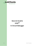
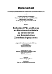
• Check for the presence of the resistor R6 in the rear side as seen in 3.
• Add a 4700 Ohm resistor in R4, R5 and R6,
• Mount again with an inverse order.
Figure 3: FILA board and location where resistors iR4, R5 and R6 are
5
5.2
HARDWARE UPDATES
14
The PC block
The PC block is composed of a bus board at the bottom, the main computer board and two
PCI boards. The three latter boards are connected to the bus board at the bottom via a PCI bus.
Three aluminium pieces hold the whole block together, but unfortunately the block is physically
unstable and some cards tend to unplug partially. The upper aluminium piece serves as support
for the cards and plates, since all of them are screwed there. The bottom piece is attached to
the bus board and has holes where the plates are inserted (but not fixed). The aluminium block
has 6 slots, of which 3 are for the boards, and other 3 for connectors (USB, PS2 and serial and
parallel). We have drilled a hole in the USB expansion plate and inserted a screw that fixes it to
the bottom aluminium block. In this way this plate acts as a physical bridge between the upper
and lower aluminium pieces and holds the block together preventing the cards from unplugging.
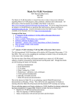
Fig. 4 shows a view of the old block, with an empty place where the new USB expansion plate
is now.
Figure 4: Block with the old main computer board. The upper aluminium piece (to the left in
the picture) to where the cards are screwed and the bottom one (to the right in the picture) to
which the bus board is screwed are connected by the card plates.
5.3
The main computer board
In July 2011, the DBBC stopped working and did not boot. After taking the whole equipment
to the lab, we discovered that the main board was burnt. This was not obvious to spot since
the burnt area was below the microprocessor fan and previously we suspected of faulty power
supply. Fig. 5 shows the old board with the burnt area encircled.
A new main computer board and two power supplies were delivered by HAT-Lab to replace the faulty ones. Only the main board was replaced; the power supplies were returned
to MPI. The new board, an HSB-945P, required to place a jumper in connector CN1 (ATX
6
CALIBRATION PROCEDURE
15
Figure 5: Old main computer board with the burnt area encircled.
Power Control Connector) to start up. We also connected an USB extender board with two
USB connectors.
The new main computer board required a new Flash card with drivers. An 8 Gb card was
provided by M. Wunderlich from MPIfR in Bonn. The card already had the latest DBBC server
software and firmware, and the Windows setup properly configured.
6
Calibration procedure
The DBBC needs to be calibrated to operate in an optimum phase regime. According to D.
Gragham this should be renamed as ”clock phase adjustement”. The data from the Analog to
Digital converter travels to the FPGAs in separate tracks. The 8 data bits may arrive at a slighlty
different time to the FPGAs. It is advisable to shift the phase of the clock in small steps so that
the clock signal matches the data when they arrive at the FPGA. This is achieved by injecting
a tone and by finding which step of the clock causes the purest signal in the FPGA with low
sidelobes in other tracks.
The calibration is achieved by injecting a -15 dBm 764 MHz signal from a synthesizer and
running command ”calibration”. Since the signal is between 500 Mhz and 1000 MHz, it is
very important to set correctly the filters in the IF, before starting the calibration:
dbbcifa=1,agc,1
dbbcifb=1,agc,1
dbbcifc=1,agc,1
dbbcifd=1,agc,1
6
CALIBRATION PROCEDURE
16
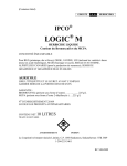
Figure 6: Results from the calibration. The clock phases for each IF module (X axis) are chosen
where the minimum for each curve happens. We have used a logarithmic scale because there
are more than 3 orders of magnitude between the minimum and the maximum. In this case the
clock phases to be used in the file would be: 97, 102, 236 and 103 for modules A, B, C and D
respectively
7
CONNECTION TO THE FIELD SYSTEM
17
It is advisable to split the signal in 4 parts and inject it in the first entry of each IF (A1,
B1, C1, D1). It is not necessary to repeat this same procedure in all entries of the IFs. The
calibration should be repeated to guarantee the consistency of the results. The procedure takes
some time to complete. In the first versions of the control software it generated a file with five
columns, the first one is the clock step and the last four columns contain the values. In the
latest versions the control software displays the columns on the screen as they are generated
and delivers a final value at which the measured values get a minimum. Below we include an
example:
.....
254 00040
254 00119
254 00410
255 00046
255 00122
255 00475
min1 00013 ele1 0
min2 00000 ele2 0
minM1 00032 ele1 97
minM2 00036 ele2 102
Enter Command:
254 00609
255 00697
min3 00000 ele3 0
minM3 00046 ele3 236
min4 00000 ele4 0
minM4 00037 ele4 103
According to the previous example, the lowest values were 32 at step (clock phase) 97 for
IF A, 36 at step 102 for IFB, 46 at step 236 for IFC and 37 for IFD at step 103. Clock phases
97, 102, 236 and 103 should be used in the configuration file. Line with min1, min2, min3,
min4 were discarded since they were outlayers (see fig 6).
Usually a periodic signal is obtained and in case two minimums are found, the first minimum
is the best option. Once the step at which the minimum for each of the four columns (four IFs)
is determined, these four values should be inserted in file dbbc_config_file.txt, under
directory dbbc_conf. This file contains several columns per BBC: frequency and bandwidth.
Then it contains four numbers with the agc point and other four that represent a clock phase
value. Below we include the current version (21/9/2011):
1 dbbc2.bit 597.00 16
1 dbbc2.bit 682.00 16
1 dbbc2.bit 853.00 16
1 dbbc2.bit 938.00 16
1 dbbc2.bit 597.00 16
1 dbbc2.bit 682.00 16
1 dbbc2.bit 853.00 16
1 dbbc2.bit 938.99 16
1 dbbc2.bit 597.00 16
1 dbbc2.bit 682.00 16
1 dbbc2.bit 853.00 16
1 dbbc2.bit 938.00 16
1 dbbc2.bit 597.00 16
1 dbbc2.bit 682.00 16
1 dbbc2.bit 853.00 16
1 dbbc2.bit 938.00 16
55000 50000 50000 50000
97 102 236 103
CAT1 1024
Fig. 6 shows an example of the output file obtained from the calibration procedure in logarithmic scale to be able to determine clearly the minima.
7
Connection to the Field System
The connection between the Field System (version 10.9.4) and the DBBC has been written
by David Graham (MPIfR) taking the Mark5C client as a stub for the code. We installed the
software provided by him in the Field System computer as station software and tested it successfully.
7
CONNECTION TO THE FIELD SYSTEM
7.1
18
Installation
The installation procedure is described below:
• Update the list of station commands by modifying file stcmd.ctl. Four commands
were added: dbbcinit, dbbc, dbbcrelink, dbbcclose. The current version of
this file is included below:
*********STATION
SEG
*COMMAND
wx
stq
calnoise
stq
phasecal
stq
calmm
stq
gps-fmout
stq
cable
qkr
cablelong
qkr
tqsys
stq
newlo
stq
rxreset
stq
dbbcinit
stq
dbbc
stq
dbbcrelink
stq
dbbcclose
stq
SPECIFIC COMMANDS**************
SBPA BO
0101 01 FFFFFFFFF
0201 01 FFFFFFFFF
0202 01 FFFFFFFFF
0203 01 FFFFFFFFF
0401 01 FFFFFFFFF
1301 01 FFFFFFFFF
7601 01 FFFFFFFFF
0501 01 FFFFFFFFF
0601 01 FFFFFFFFF
0701 01 FFFFFFFFF
0800 01 FFFFFFFFF
0829 01 FFFFFFFFF
0830 01 FFFFFFFFF
0831 01 FFFFFFFFF
• Update the list of station programs. One line was added: dbbccn. The current version of
the file is included below:
* Put site-specific programs here that should
* be started by the Field System.
* antcn should not be here
erchk n xterm -geom 99x16+0+518 -title ERRORS -e erchk &
stqkr n stqkr &
dbbccn n dbbccn &
• Copy the old directory tree to a new folder were we add the new features:
su - prog
cp -r /usr2/st /usr2/st-1.1.0
• As root, modify the station software directory link:
cd /usr2
ln -s st-1.1.0 st
• As prog, create directory /usr2/st/control and there, file dbbc.ctl, which contains
the DBBC IP address, port number and port timeout.
* /usr2/st/control/dbbcad.ctl
* control file for DBBC
IP-Nr.
Port timeout
*hostname
************************************
192.168.0.206 4000 500
• Create directories /usr2/st/dbbccn which contains the code for a binary program that
talks to the DBBC using TCP sockets and /usr2/st/dbbc with software that manages
DBBC commands. All this code was provided by D. Graham (MPIfR) and we do not
include it here. Refer to his code for further information. We modified the switch cases in
stqkr to match the numbers in file stcmd.ctl. The code contains debugging sentences
which can be activated, in order to monitor if it works correctly or not. This should be
done from the prog account.
7
CONNECTION TO THE FIELD SYSTEM
19
• Modify the /usr2/st/Makefile to include the compilation in the new directories. We
include below the new updated line:
EXEC_DIR = antcn cheks stalloc stdealloc sterp dbbc stqkr dbbccn autoftp
• It is advisable to include the following lines in file /usr2/st/antcn/antcn.c:
#include <string.h>
and in file /usr2/st/stlib/stm_util.c:
#include <stdlib.h>
• From the prog account, compile all the station software again:
cd /usr2/st
make rmdoto rmexe all
• Reboot the Field System computer and start the Field System
The dbbc commands are managed by stqkr which sends instructions to binary program
dbbccn. This program is continuously running and is started by the FS. It opens a socket
connection to the DBBC server and sends receives messages to/from the DBBC.
7.2
Test and usage
All commands for the DBBC work as the mk5 ones, they are prepended by the keyword dbbc=
and followed by accepted DBBC keywords. For example, to monitor the first DBBC (01), one
should enter:
dbbc=dbcc01
There are three more commands which do not follow this rule: dbbcinit which starts the
communication with the DBBC server, dbbcrelink which restablishes the connection to the
DBBC server and dbbclose which closes the socket connection. The first and last commands
should be used only once, to open and close the communication with the DBBC server.
Below we show an example of the Field System log after 3 commands:
2011.256.07:37:01.32;dbbcinit
2011.256.07:37:13.50;dbbc=dbbc01
2011.256.07:37:13.50/dbbc/dbbc01/597.000000,a,16,16,1,agc,10,10,773,1005,0,0
2011.256.07:37:53.34;dbbc=dbbcform
2011.256.07:37:53.35/dbbc/dbbcform/geo
and here we show the messages in the server:
Listening Socket started
Waiting for connection on port 4000
Client 192.168.0.135 connection accepted
Command from 192.168.0.135: Command received: dbbc01 7
Command from 192.168.0.135: Command received: dbbcform 90
Command from 192.168.0.135:
7
CONNECTION TO THE FIELD SYSTEM
20
Below we comment on some interesting commands. We will use some examples to explain
its content (see Graham 2010, and Tuccari 2010 for further details):
• dbbc=pps_sync. This command synchronizes the FPGAs to the 1 PPS external signal.
From that command on, the cards will flash in sync (lower LED of the upper group).
• dbbc=dbbcifa=1,agc,1. The first parameter sets input 1 for IF module A (possibles
choices are 1, 2, 3 and 4, since there are 4 inputs as can be seen in Fig. 2). The mode
may be ”auto” or ”manual”. The best option is to use auto, in which the gain is updated
every second. The third parameter may take values 1 and 2. If it is 1 a filter between
500-1000 MHz is used, if it is 2 a filter between 10-500 MHz is used. The monitor line
provides information on the attenuator level (second parameter) and on the level read (last
parameter), which is proportional to the RMS detected voltage:
dbbcifa/1,39,agc,1,50082
Tipical values should be around 50000 if the the configuration file is set to adjust the level
to this count.
• dbbc=dbbcform=geo. The track map is chosen to be ”astronomy” or ”geodetic”. The
map is the same as the VSI4 module, and is described by Smythe 2004. The ”geo” mode
uses 14 tracks USB and 2 tracks LSB. The ”astro” mode uses 8 tracks ”USB” and 8 tracks
”LSB”. Further selection and the possibility to use 1 or 2 bits is done in the Mark5B.
• dbbc=dbbcmon=01u. This command sends the the USB signal from BBC01 to the analog monitor output in the rear of the DBBC.
• dbbc=dbbc01=569.99,a,8,8,1,agc,1,1. This is the most useful and used command. It sets the frequency of each bbc, the IF input, the bandwidth of the USB and LSB,
the integration time, the automatic or manual gain control. The last two numbers are used
to set the gain in manual mode and the accepted numbers are between 1 and 16 (?). The
monitor line includes two more numbers to be used for 80 Hz switched voltages.
dbbc01/597.000000,a,16,16,1,agc,10,10,164,168,0,0
• dbbc=calibrate. It starts a calibration procedure which takes 2 minutes and displays
256 lines with 5 columns in real time. At the end of the process, the 256 lines appear in
8 columns grouped in pairs and two final lines indicate the index at which the minimum
happens for each IF.
• dbbc=reconf. This reconfigures the DBBC by loading the firmware to the FPGAs again
but apparently does not read again the configuration file. That means that a modification
in the configuration file is not taken into account. It is necessary to reboot the computer
to achieve that.
• mag_thr=1,0.042. Magnitude threshold correction factor. Should be 0.042 or 0.065
depending on the bandwidth. If an 80 Hz signal is used for calibration it should be 1.4
times higher.
7
CONNECTION TO THE FIELD SYSTEM
21
• dbbcstat=bbcn,m. Computes the statistics of the high states and displays them in hexadecimal compared with 0x7A12. According to D. Graham in the current version, S (sign)
and M (magnitude) bits are interchanged. The magnitude bit (once interchanged) does not
work. Only the sign one does. Below the stats for the sign bit (once interchanged):
dbbc8 M STAT USB 0X5618 LSB 0X5625
• version. Should return the version number of the control software:
version/Feb 21 2011
7.3
Procedure modification
The current way to use the DBBC in standard experiments is to modify the procedures generated by drudg and replace some commands. D. Graham provided a perl script which modifies procedures for VSI4 VLBA terminals and which we include below. This script inserts a
dbbc=pps_sync command in the exper_initi procedure, replaces all ocurrences of vsi4=geo
by two lines:
dbbc=dbbcform=geo
dbbc=dbbcform
or astro instead of geo, and replaces all ocurrences of bbc by dbbc=dbbc.
Below we include the perl script:
#!/usr/bin/perl
#make dbbc procedures: only for astro and bbc1-8
#input:procedures made for VLBA5/mk5b
open(fi,"$ARGV[0]");
while(<fi>){
chomp;
s/< VLBA5/< DBBC/;
s/vsi4=vlba/dbbc=dbbcform=astro/;
s/vsi4=geo/dbbc=dbbcform=geo/; #don’t use this!
s/vsi4/dbbc=dbbcform/;
(@ss)=split();
if($ss[0] eq "define"){
if(substr($ss[1],0,3) eq "bbc"){$bbcdefine=1};
if($ss[1] eq "exper_initi"){$init=1};
}
if(($bbcdefine ==1) && (substr($_,0,3) eq "bbc")){
(@seq)=split("=",$_);
$bbcn=substr($seq[0],4,1); #which bbc?
(@parms)=split(’,’,$seq[1]);
if($parms[0] >499){$filter="1";} else {$filter="2";}
if($parms[1] eq "a"){$ifin="1";} #IF a split to both inputs 1
if($parms[1] eq "b"){$ifin="2";} #IF b to both ips 2
if($parms[1] eq "c"){$ifin="3";} #probably not connected
if($parms[1] eq "d"){$ifin="4";}
if($seq[0] eq "bbc01"){$ifboard1=$ifin.",agc,".$filter;}
if($seq[0] eq "bbc05"){$ifboard2=$ifin.",agc,".$filter;}
s/bbc/dbbc=dbbc/;
}
if($ss[0] eq "enddef"){
if($init == 1){
print "dbbc=pps_sync\n"; #at end of initi
}
if($bbcdefine == 1){
print "dbbc=dbbcifa=$ifboard1\n"; #at end of bbc proc, IF settings
print "dbbc=dbbcifb=$ifboard2\n";
}
7
CONNECTION TO THE FIELD SYSTEM
$init=0;
$bbcdefine=0;
}
print "$_\n";
}
and here we can see two versions of the same procedure. Old version:
define proc_library 11168230430x
enddef
define exper_initi
11168230421x
proc_library
mk5=DTS_id?
mk5=OS_rev?
mk5=SS_rev?
mk5=status?
enddef
define setup01
11168230429x
pcalon
tpicd=stop
pcald=stop
mk5b_mode=ext,0xFFFFFFFF,1
mk5b_mode
vsi4=vlba
vsi4
bbc01d
ifd01
bank_check
tpicd=no,2000
tpicd
enddef
define bbc01d
11168230429x
bbc01=637.49,a,16.000,16.000
bbc02=637.49,c,16.000,16.000
bbc03=669.49,a,16.000,16.000
bbc04=669.49,c,16.000,16.000
bbc05=701.49,a,16.000,16.000
bbc06=701.49,c,16.000,16.000
bbc07=733.49,a,16.000,16.000
bbc08=733.49,c,16.000,16.000
enddef
define ifd01
11168230430x
ifdab=0,0,nor,nor
ifdcd=0,0,nor,nor
lo=
newlo=0
lo=loa,21550.00,usb,rcp,1.000
newlo=a
lo=loc,21550.00,usb,lcp,1.000
newlo=c
enddef
New version:
define proc_library
enddef
define exper_initi
proc_library
mk5=DTS_id?
mk5=OS_rev?
mk5=SS_rev?
mk5=status?
dbbc=pps_sync
enddef
define setup01
pcalon
tpicd=stop
11168230430x
11168230421x
11168230429x
22
REFERENCES
23
pcald=stop
mk5b_mode=ext,0xFFFFFFFF,1
mk5b_mode
dbbc=dbbcform=astro
dbbc=dbbcform
bbc01d
ifd01
bank_check
tpicd=no,2000
tpicd
enddef
define bbc01d
11168230429x
dbbc=dbbc01=637.49,a,16.000,16.000
dbbc=dbbc02=637.49,c,16.000,16.000
dbbc=dbbc03=669.49,a,16.000,16.000
dbbc=dbbc04=669.49,c,16.000,16.000
dbbc=dbbc05=701.49,a,16.000,16.000
dbbc=dbbc06=701.49,c,16.000,16.000
dbbc=dbbc07=733.49,a,16.000,16.00
dbbc=dbbc08=733.49,c,16.000,16.000
dbbc=dbbcifa=1,agc,1
dbbc=dbbcifb=1,agc,1
enddef
define ifd01
11168230430x
ifdab=0,0,nor,nor
ifdcd=0,0,nor,nor
lo=
newlo=0
lo=loa,21550.00,usb,rcp,1.000
newlo=a
lo=loc,21550.00,usb,lcp,1.000
newlo=c
enddef
References
[Graham 2009] D. Graham, ”Setting up DBBC for geodetic VLBI experiments”, Private Communication, 2009.
[Graham 2010] D. Graham, ”DBBC FS Control”, Private communication, 2010.
[Tuccari 2010] G. Tuccari, ”DBBC Command set”, 2010.
[Smythe 2004] D. Smythe, Haystack Mark5 Memo 16, 2004