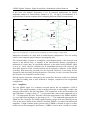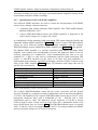
1
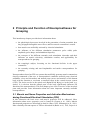
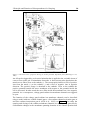
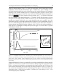
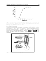
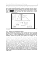
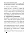
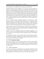
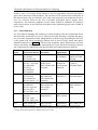
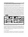
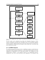
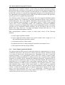
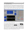
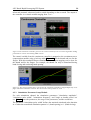
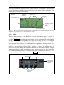
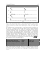
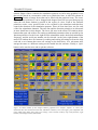
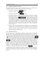
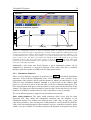
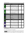
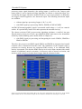
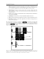
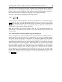
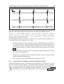
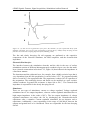
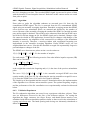
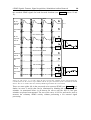
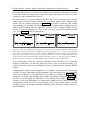
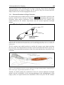
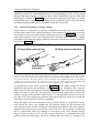
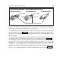
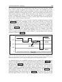
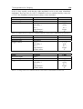
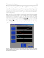
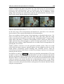
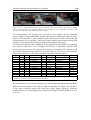
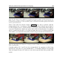
4 PC Based Rapid Prototyping FES System
59
afterwards summed, subtracted, and/or scaled depending on the set mode. The output of
the controller is a control variable ranging from -1 to 1.
Figure 22:The continuous controller generates the control variable for the two control algorithm "sliding
potentiometer control" and "analog EMG control".
The control variable from the continuous controller is mapped to the recruitment curve
compensation module using a look-up table (Figure 23) for the thumb and one for the
fingers. With this method different stimulation sensor output mapping can be done for
the thumb and for the fingers. For example, the thumb can only be stimulated during
hand closing and not during hand opening.
Figure 23: The control variable that is generated in the continuous controller is mapped differently to the
finger and thumb stimulation channels. For this task two look-up tables are used.
4.3.3 Stimulation Parameter Setup Module
For each stimulation channel the stimulation parameters "stimulation amplitude",
"stimulation pulse width", "stimulation frequency", and "single or double pulses" are
set. Table 2 shows the parameters, the range of the parameters, and the resolutions.
The parameter "stimulation pulse width" defines the maximal stimulated pulse duration
in µs when the normalized stimulation pattern is 1 (hand opening) or -1 (hand closing).