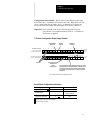
1
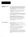
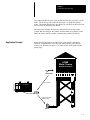
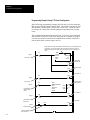
Important User Information Solid state equipment has operational characteristics differing from those of electromechanical equipment. “Application Considerations for Solid State Controls” (Publication SGI-1.1) describes some important differences between solid state equipment and hard–wired electromechanical devices. Because of this difference, and also because of the wide variety of uses for solid state equipment, all persons responsible for applying this equipment must satisfy themselves that each intended application of this equipment is acceptable. In no event will the Allen-Bradley Company be responsible or liable for indirect or consequential damages resulting from the use or application of this equipment. The examples and diagrams in this manual are included solely for illustrative purposes. Because of the many variables and requirements associated with any particular installation, the Allen-Bradley Company cannot assume responsibility or liability for actual use based on the examples and diagrams. No patent liability is assumed by Allen-Bradley Company with respect to use of information, circuits, equipment, or software described in this manual. Reproduction of the contents of this manual, in whole or in part, without written permission of the Allen-Bradley Company is prohibited. 1991 Allen-Bradley Company, Inc. PLC, SLC Dataliner, PanelView, and RediPANEL are registered trademarks of Allen-Bradley Company, Inc. Table of Contents Distributed I/O Scanner A–B Preface Using this Manual Purpose of this Manual . . . . . . . . . . . . . . . . . . . . . . . . . . . . . . . . . . . . . . Contents of this Manual . . . . . . . . . . . . . . . . . . . . . . . . . . . . . . . . . . . . . . Related Publications . . . . . . . . . . . . . . . . . . . . . . . . . . . . . . . . . . . . . . . . Intended Audience . . . . . . . . . . . . . . . . . . . . . . . . . . . . . . . . . . . . . . . . . . Conventions . . . . . . . . . . . . . . . . . . . . . . . . . . . . . . . . . . . . . . . . . . . . . . . Warnings and Cautions . . . . . . . . . . . . . . . . . . . . . . . . . . . . . . . . . . . . . . Introduction Chapter 1 Chapter Objectives . . . . . . . . . . . . . . . . . . . . . . . . . . . . . . . . . . . . . . . . . . DIO System Overview . . . . . . . . . . . . . . . . . . . . . . . . . . . . . . . . . . . . . . . DIO Link Overview . . . . . . . . . . . . . . . . . . . . . . . . . . . . . . . . . . . . . . . . . DH–485 Data Link Overview . . . . . . . . . . . . . . . . . . . . . . . . . . . . . . . . . DIO Scanner Features . . . . . . . . . . . . . . . . . . . . . . . . . . . . . . . . . . . . . . . LEDs . . . . . . . . . . . . . . . . . . . . . . . . . . . . . . . . . . . . . . . . . . . . . . . . . DIO Link Connector . . . . . . . . . . . . . . . . . . . . . . . . . . . . . . . . . . . . . Chassis Ground Terminal . . . . . . . . . . . . . . . . . . . . . . . . . . . . . . . . . How the Scanner Interacts with the SLC Processor . . . . . . . . . . . . . . . . Scanner Configurations . . . . . . . . . . . . . . . . . . . . . . . . . . . . . . . . . . . . . . Scanner Baud Rate . . . . . . . . . . . . . . . . . . . . . . . . . . . . . . . . . . . . . . . . . . I/O Block Addressing . . . . . . . . . . . . . . . . . . . . . . . . . . . . . . . . . . . . . . . Wiring and Installation 1–1 1–1 1–2 1–2 1–3 1–3 1–3 1–3 1–4 1–5 1–5 1–5 Chapter 2 Chapter Objectives . . . . . . . . . . . . . . . . . . . . . . . . . . . . . . . . . . . . . . . . . . Determining Block Requirements . . . . . . . . . . . . . . . . . . . . . . . . . . . . . . Determining Scanner and SLC Processor Requirements . . . . . . . . . . . . Wiring the DIO Link . . . . . . . . . . . . . . . . . . . . . . . . . . . . . . . . . . . . . . . . Wiring the DH–485 Data Link . . . . . . . . . . . . . . . . . . . . . . . . . . . . . . . . Scanner Installation . . . . . . . . . . . . . . . . . . . . . . . . . . . . . . . . . . . . . . . . . Configuration and Programming P–1 P–1 P–2 P–2 P–2 P–3 2–1 2–1 2–1 2–2 2–4 2–6 Chapter 3 Chapter Objectives . . . . . . . . . . . . . . . . . . . . . . . . . . . . . . . . . . . . . . . . . . SLC Processor Configuration . . . . . . . . . . . . . . . . . . . . . . . . . . . . . . . . . Programming . . . . . . . . . . . . . . . . . . . . . . . . . . . . . . . . . . . . . . . . . . . SLC Processor Input and Output Images . . . . . . . . . . . . . . . . . . . . . . . . 7 I/O Block Configuration Input Image . . . . . . . . . . . . . . . . . . . . . . 7 I/O Block Configuration Input Image Example . . . . . . . . . . . . . . . 7 I/O Block Configuration Output Image . . . . . . . . . . . . . . . . . . . . . Control Word (Word 0) . . . . . . . . . . . . . . . . . . . . . . . . . . . . . . . . . . . 7 I/O Block Configuration Output Image Example . . . . . . . . . . . . . Control Word Configuration Information . . . . . . . . . . . . . . . . . . . . . 30 I/O Block Configuration Input Image . . . . . . . . . . . . . . . . . . . . . 3–1 3–2 3–2 3–3 3–3 3–3 3–4 3–4 3–5 3–5 3–6 i Table of Contents Distributed I/O Scanner 30 I/O Block Configuration Input Image Example . . . . . . . . . . . . . . 30 I/O Block Configuration Output Image . . . . . . . . . . . . . . . . . . . . Control Word (Word 0) . . . . . . . . . . . . . . . . . . . . . . . . . . . . . . . . . . . 30 I/O Block Configuration Output Image Example . . . . . . . . . . . . Control Word Configuration Information . . . . . . . . . . . . . . . . . . . . . Use of the Communication Status Words . . . . . . . . . . . . . . . . . . . . . . . . Use of the Control Word . . . . . . . . . . . . . . . . . . . . . . . . . . . . . . . . . . . . . Application Example . . . . . . . . . . . . . . . . . . . . . . . . . . . . . . . . . . . . . . . . Programming Example Using 7 I/O Block Configuration . . . . . . . . Operation and Troubleshooting Specifications Chapter 4 Chapter Objectives . . . . . . . . . . . . . . . . . . . . . . . . . . . . . . . . . . . . . . . . . . Start Up . . . . . . . . . . . . . . . . . . . . . . . . . . . . . . . . . . . . . . . . . . . . . . . . . . Normal Operation . . . . . . . . . . . . . . . . . . . . . . . . . . . . . . . . . . . . . . . . . . Scanner Slot Disable Operation . . . . . . . . . . . . . . . . . . . . . . . . . . . . . . . . Loss of Communications . . . . . . . . . . . . . . . . . . . . . . . . . . . . . . . . . . . . . Scanner Test Mode Operation . . . . . . . . . . . . . . . . . . . . . . . . . . . . . . . . . 30 I/O Block Configuration . . . . . . . . . . . . . . . . . . . . . . . . . . . . . . . 7 I/O Block Configuration . . . . . . . . . . . . . . . . . . . . . . . . . . . . . . . . I/O Block Hold Last State Operation . . . . . . . . . . . . . . . . . . . . . . . . . . . Status LEDs . . . . . . . . . . . . . . . . . . . . . . . . . . . . . . . . . . . . . . . . . . . . . . . Troubleshooting . . . . . . . . . . . . . . . . . . . . . . . . . . . . . . . . . . . . . . . . . . . . Error Codes . . . . . . . . . . . . . . . . . . . . . . . . . . . . . . . . . . . . . . . . . . . . . . . 4–1 4–1 4–2 4–3 4–3 4–4 4–4 4–4 4–5 4–6 4–7 4–8 Chapter 5 Chapter Objectives . . . . . . . . . . . . . . . . . . . . . . . . . . . . . . . . . . . . . . . . . . Scanner Operating Specifications . . . . . . . . . . . . . . . . . . . . . . . . . . . . . . Network Specifications . . . . . . . . . . . . . . . . . . . . . . . . . . . . . . . . . . . . . . ii 3–7 3–8 3–8 3–9 3–9 3–10 3–10 3–11 3–12 5–1 5–1 5–1 A–B P Preface Using This Manual Read this chapter to familiarize yourself with the rest of the manual. It provides information concerning the: • • • • contents of this manual intended audience conventions used warnings and cautions Purpose of this Manual This manual describes how the Distributed I/O (DIO) Scanner, Catalog Number 1747–DSN, is used in the Distributed I/O System. It will help you: • understand the DIO system and its components • select appropriate DIO system components for your application • install, program, start up, and operate your DIO Scanner Contents of this Manual This manual provides specific information regarding scanner installation and operation. In addition, it offers general information on the other DIO system components. The following table identifies the chapters, titles and contents. Chapter Title Purpose P Preface 1 Introduction 2 Wiring and Installation 3 Configuration and Programming 4 Start Up, Operation, and Troubleshooting 5 Specifications Contains DIO Scanner and DIO System specifications. A Appendix A Contains I/O Block Dip switch settings. Familiarizes you with the rest of the manual. Provides an overview of the DIO system. Describes how to install and wire the DIO Scanner. Describes how to program the SLC processor that controls the DIO Scanner and DIO system. Provides LED status information, troubleshooting suggestions and error codes. Preface Related Publications The following publications are available to assist you in the use of your DIO system: • APS Library, Catalog Number 1747–ND001 Series B (shipped with Advanced Programming Software) • HHT Library, Catalog Number 1747–ND002 Series B (shipped with HHT) • SLC 500 Fixed and Modular Controller Library, Catalog Number 1747–ND003 Series A (shipped with SLC processor) • Block I/O User’s Manual, Publication 1701–6.5.1–DU1 (shipped with block I/O) Intended Audience We assume that you have a working knowledge of SLC 500 products. If you do not, obtain the proper training before using the DIO Scanner. Conventions The following terms are used throughout this manual: Term Definition 5/01 processor Refers to the SLC 5/01 processor, Catalog Number 1747–L511 and –L514. 5/02 processor Refers to the SLC 5/02 processor, Catalog Number 1747–L524. DH–485 Data Link DIO DIO link DIO system I/O blocks Isolated Coupler programming device P–2 Refers to an Allen–Bradley network supporting the transfer of processor program information between SLC processors and programming devices. This network may consist of multiple processors and/or programming devices. Acronym for “Distributed I/O” Refers to an Allen–Bradley network supporting high speed transfer of control information. This network consists of a single scanner and multiple I/O blocks. Refers to the scanner, I/O blocks and programming devices properly connected to the DH–485 data link and DIO link. Refers to the Bulletin 1791 I/O blocks. Refers to the DH–485 Data Link Isolated Link Coupler, Catalog Number 1747–AIC. The Isolated Coupler is used to connect an SLC processor and/or programming device to the DH–485 Data Link. Refers to either an SLC 500 HHT (Catalog Number 1747–PT1) or a PC with Advanced Programming Software (APS) (Catalog Number 1747–PA2E). The HHT or APS is used to program and monitor the SLC processor. rack Refers to any SLC 500 Modular Rack, Catalog Numbers 1746–A4, –A7, –A10 and –A13. The SLC processor and I/O modules are installed in the SLC Rack. scanner Refers to the Catalog Number 1747–DSN Distributed I/O scanner module. SLC processor Refers to both the SLC 5/01 and 5/02 modular processors. The SLC processor controls the I/O modules in the SLC Rack, including the scanner. Preface Warnings and Cautions Both warnings and cautions are used in this manual. WARNING: ! This symbol means people can be injured if procedures are not followed. WARNING: This symbol means there is a potential shock hazard and people can be injured if procedures are not followed. ! CAUTION: This symbol means equipment can be damaged if procedures are not followed. CAUTION: This means there is a potential shock hazard and equipment can be damaged if procedures are not followed. P–3 Chapter A–B 1 Introduction Chapter Objectives This chapter contains the following information: • DIO system overview • DIO Link overview • DH–485 Data Link overview • how the scanner interacts with the SLC processor • scanner features Important: Use the DIO scanner in any SLC 500 Modular Hardware system. The scanner cannot be used in SLC 500 Fixed Hardware systems. DIO System Overview The DIO system consists of an SLC processor, a scanner, an Isolated Coupler and I/O blocks. These devices form the DIO System when they are properly connected to the DIO Link and the DH–485 Data Link as shown below. The DIO Link and the DH–485 Data Link are independent networks. The DIO Link consists of the scanner and I/O blocks. It enables the SLC processor to exchange input and output information with up to 30 I/O blocks. Output data is transferred from the SLC processor to the scanner, which then transmits the data to the appropriate I/O block via the DIO Link. The scanner receives input data from the I/O blocks via the DIO Link. The scanner then provides this data to the SLC processor. The maximum length of the DIO Link is 2,500 feet (762 meters) using Belden 9463 cable. The SLC processor and programming devices communicate using the DH–485 Data Link. The DH–485 port located on each I/O block allows remote programming and/or monitoring of the SLC processor. It does not directly control the I/O block. Connecting a programming device to any I/O block programming port allows the programming device to communicate with the SLC processor. The maximum length of the DH–485 Data Link is 4,000 feet (1,219 meters) using Belden 9842 cable. SLC Processor Scanner Programming Device (HHT) Isolated Coupler I/O blocks DH–485 Data Link DIO Link Chapter 1 Introduction DIO Link Overview The DIO Link is an Allen–Bradley communications network supporting high speed transfer of control information. A DIO Link consists of a single master device (the scanner) and multiple slave devices (the I/O blocks). The scanner and I/O blocks are daisy chained together by a single twisted pair cable (Belden 9463). Each I/O block is assigned a I/O block number from 1 to 31 (excluding 16, which is invalid) by setting the appropriate dip switches on the I/O block. I/O block numbers must be assigned consecutively. For example, if 5 I/O blocks are used, they must be assigned I/O block numbers 1 to 5. I/O blocks do not have to be wired in a contiguous order. For example, I/O block 5 can follow I/O block 2. The inputs and outputs for each I/O block are mapped into the words in the SLC processor’s input and output images. These words correspond to the scanner’s slot number and the I/O block’s number. For example, if the scanner is installed in slot 2 of the SLC Rack, I/O block number 1 will have: • its input data reflected in word 1 of the slot 2 input image • its output data reflected in word 1 of the slot 2 output image. The scanner communicates with each I/O block in a round robin fashion. The scanner initiates communications with an I/O block by first sending its output data. The I/O block then responds by sending its input data back to the scanner. After the scanner completes its I/O transfer with the last I/O block, it begins another transfer with the first I/O block. DH–485 Data Link Overview The DH–485 Data Link is an Allen–Bradley communications network that supports the transfer of information between programming devices and SLC processors. The programming device and SLC processor are attached to the DH–485 Data Link using either an Isolated Coupler or an I/O block. The DH–485 Data Link may consist of multiple Isolated Couplers and/or I/O blocks that provide for communication between several programming devices and/or processors. The Isolated Couplers and I/O blocks are daisy chained together by a single twisted pair cable (Belden 9842) to form the DH–485 Data Link. The programming devices and SLC processors are attached to the Isolated Coupler or I/O block using Communication Cables (Catalog Numbers 1747–C10 and –C11). For additional information on the DH–485 Data Link, see the Installation and Operation Manual for SLC 500 Modular Hardware Style Programmable Controllers, Publication 1747–804. 1–2 Chapter 1 Introduction DIO Scanner Features The DIO Scanner is featured below. SCANNER SN SCANNER FAULT LED COMM LED DIO Link Connector Chassis Ground Terminal Cable Tie LEDs Two LEDs are provided to monitor scanner and communications status. FAULT LED – used to monitor scanner status. Its normal state is off. The FAULT LED is off whenever the scanner is operating properly. COMM LED – used to monitor communications with the I/O blocks. Its normal state is solid green. The COMM LED status information is valid only when the FAULT LED is off. DIO Link Connector This three pin male connector connects the scanner to the DIO Link. The Allen–Bradley repair part number is W22112–046–03. Chassis Ground Terminal The chassis ground terminal provides a convenient location for grounding the DIO cable shield. The cable shield should be connected to chassis ground at one point on the DIO Link. 1–3 Chapter 1 Introduction How the Scanner Interacts with the SLC Processor The SLC processor scan consists of an input, program, and output scan. During the input scan, the scanner input file (which contains the on/off input status of all configured I/O blocks) is read into SLC processor memory. During the SLC program scan, the input information is used by your application program. An SLC output file, based on the logic of your program, is then written to the scanner during the output scan. The scanner’s scan consists of reading and writing data to all I/O blocks. For example if three I/O blocks are attached, the scan consists of three read/write cycles. The SLC processor scan and the scanner scan operate asynchronously, or independent of each other. The SLC processor reads the scanner input file during its input scan and writes the output file to the scanner during the output scan. The scanner continues reading inputs and writing outputs to the scanner input file, independently of the SLC processor scan. Depending on your network and application program size, it is not uncommon for the scanner to complete a number of scans before the SLC processor reads the scanner’s input file. The figure shown below illustrates the asynchronous operation of the SLC processor and scanner. SLC Processor Scan Scanner Scan Scanner Input File SLC Input File Output 3 The SLC processor reads the Output scanner input file into the SLC input file, processes it and creates an SLC output file. The SLC output file is transferred to the scanner during the output scan. Input 1 Input Input 3 Output 1 Output 2 Program The scanner updates its input file each time it scans an I/O block. The scanner may scan all three of its configured I/O blocks many times before the SLC Processor reads the scanner’s input file. Input 2 Scanner Output File SLC Output File SLC Processor Scanner I/O block 1 1–4 I/O block 2 I/O block 3 Chapter 1 Introduction Scanner Configurations The scanner can be configured for two different modes of operation. These modes, or configurations, are referred to as 7 and 30 I/O block configurations. When the scanner is configured for a 7 I/O block configuration, the scanner addresses up to seven I/O blocks. The SLC 5/01 and 5/02 processors support the 7 I/O block configuration. When the scanner is configured for a 30 I/O block configuration, the scanner addresses up to 30 I/O blocks. The SLC 5/02 processor supports the 30 I/O block configuration. The scanner cannot be used with SLC 500 Fixed Hardware Systems. Scanner Baud Rate Since the scanner operates at a fixed baud rate of 230.4K, configure the I/O blocks for 230.4K baud. This lets the scanner communicate with the I/O blocks. I/O Block Addressing I/O blocks are addressed as I/O blocks 1 through 15 and 17 through 31. There is no I/O block 16. I/O blocks must be addressed consecutively; however, they do not have to be wired in a contiguous order. I/O block 3 I/O block 6 I/O block 2 I/O block 1 I/O block 4 I/O block 5 In the example above, the six I/O blocks are addressed in numerical order as I/O blocks 1 thru 6; however, they are not wired in numerical order. A unique address is assigned to each I/O block using dip switches located on each I/O block. These switches are also used to set the I/O block baud rate and output Hold Last State operation. For further I/O block dip switch information, see the I/O Block User’s manual, Publication 1701–6.5.1–DU1. 1–5 Chapter A–B 2 Wiring and Installation Chapter Objectives This chapter contains the information necessary to: • • • • Determining Block Requirements select the proper DIO system components install the scanner into the SLC Rack wire the DIO Link Network wire the DH–485 Data Link Network The number of I/O blocks you require is based upon the number of input and output devices called for in your functional specification. The proximity of each device must also be taken into consideration. For detailed information regarding the types of I/O blocks available and for I/O block installation and wiring instructions, refer to the I/O Block User’s Manual, Publication 1701–6.5.1–DU1. Determining Scanner and SLC Processor Requirements The number of scanners required depends upon the number of I/O blocks each scanner will be configured for and the type of SLC processor used to control the scanner. Scanners can be configured to address up to 7 or 30 I/O blocks. If you are using a 5/01 processor, the scanner can only be configured for the 7 I/O block configuration. Using a 5/02 processor allows you to configure the scanner for the 7 or 30 I/O block configuration. The scanner cannot be used with SLC 500 Fixed Hardware systems. Chapter 2 Wiring and Installation Wiring the DIO Link The scanner and I/O blocks are connected to the DIO Link in a daisy chain configuration. A daisy chain configuration is formed by connecting the scanner and I/O blocks together in a serial manner along a single section of link cable (Belden 9463). The scanner is attached to the DIO Link using its 3 position DIO Link connector, and the I/O blocks are attached to the DIO Link using 3 terminals on their 6 position DIO connector. There are no restrictions governing the spacing between each device, as long as the overall length of the DIO Link does not exceed 2,500 feet. However, no two devices may be connected to the same point on the DIO Link. 82 ohm terminating resistors must be attached at each end of the link. A termination kit is included with each scanner for this purpose. In addition, the DIO Link cable shield must be earth grounded at one point on the link. Specific attention should be paid to the DIO Link cable shield grounding, because this must be coordinated with the grounding of the DH–485 Data Link shield. Examples of correct and incorrect DIO Link configurations are shown below, and specific wiring details are provided on the following page. Correct Terminating Resistor Terminating Resistor Incorrect Terminating Resistor Terminating Resistor Correct Terminating Resistor Terminating Resistor Incorrect Terminating Resistor 2–2 Terminating Resistor Chapter 2 Wiring and Installation The DIO Link must be terminated at each end with an 82 Ohm 1/2 watt resistor. The resistor is connected across Line 1 and Line 2. In addition, Chassis Grounding Method One is illustrated below. SN SCANNER 82 Ω Terminating Resistor Clear Line 2 Shield Line 1 Shield Blue Clear Shield Blue Chassis Ground Chassis Grounding Method 1 1 DIO / DH–485 shield DIO Clear (line 2) DIO / DH–485 shield DIO Blue (line 1) 2 SHD 1 B A COM DIO Connector for the I/O block Terminating Resistor 2 SHD 1 B A COM DIO Clear (line 2) DIO Blue (line 1) 2 SHD 1 B A COM DIO Connector for the I/O block 2 SHD 1 B A COM 82 Ω Terminating Resistor 1 Because the DIO / DH–485 shields are tied together at each block, you should only connect the shield to chassis ground in one place. If you choose to ground the shields using Chassis Grounding Method 1 (shown here), do not use Chassis Grounding Method 2 (shown on page 2–5). 2–3 Chapter 2 Wiring and Installation Wiring the DH–485 Data Link The DH–485 Data Link allows a programming device to communicate with the SLC processor. Each I/O block has a programming port that allows a programming device to be connected to the DH–485 Data Link. The Isolated Coupler and I/O blocks are connected to the DH–485 Data Link in a daisy chain configuration. A daisy chain configuration is formed by connecting the Isolated Coupler and I/O blocks together in a serial manner along a single section of link cable (Belden 9842). There are no restrictions governing the spacing between each device, as long as the overall length of the DH–485 Data Link does not exceed 4,000 feet. However, no two devices may be connected to the same point on the DH–485 Data Link. Termination must be provided at each end of the link. The I/O blocks and Isolated Couplers have internal resistors for this purpose. Correct Programming Device (HHT) Last device terminated Last device must be terminated Isolated Link Coupler 1747–C11 Communication Cable Incorrect Belden 9842 Last device must be terminated 1747–C10 Communication Cable Last device terminated Correct Last device must be terminated Last device must be terminated Programming Device (APS) Incorrect Last device must be terminated Last device must be terminated Important: The device at each end of the link must be terminated using the DH–485 Termination Switch (switch 10). 2–4 Chapter 2 Wiring and Installation The Isolated Coupler is attached to the DH–485 Data Link using its 6 position DH–485 Data Link connector. The I/O blocks are attached to the DIO Link using 4 of the 6 terminals on the DIO connector. The DH–485 Data Link cable shield must be earth grounded at one point on the link. The SLC processor is connected to the Isolated Coupler with a Catalog Number 1747–C11 Communication Cable, which is included with the Isolated Coupler. The programming device is connected to the I/O block (or Isolated Coupler) using a Catalog Number 1747–C10 Communication Cable. SLC CPU Termination 3 DH–485 A DH–485 B Common Shield (drain wire) Chassis Ground TERM A B COMMON SHLD CHS GND Chassis Grounding Method 2 2 Isolated Link Coupler 1 SLC Processor 1747–C11 Communication Cable DH–485 B DH–485 A DIO / DH–485 shield 2 SHD 1 DIO Connector for the I/O block 2 SHD 1 B DH–485 Common A COM B A COM 1 The wiring scheme shown is that of a 1747–AIC Series B Link Coupler. Although the Series A Link Coupler is labeled differently, you do not have to rewire your connector. 2 Because the DIO/DH–485 shields are tied together at each block, you should only connect the shields to chassis ground in one place. If you choose to ground the shields using Chassis Grounding Method 2, do not use Chassis Grounding Method 1 (shown on page 2–3). TERM and A must be jumpered (to terminate the link) if the Isolated Coupler is at the end of the DH–485 Link. 3 2–5 Chapter 2 Wiring and Installation Scanner Installation Installation procedures for this scanner are the same as any other discrete I/O or specialty module. ! CAUTION: Disconnect power before attempting to install, remove, or wire the scanner. 1. Align the full sized scanner circuit board with the rack card guide. The first slot (slot 0) of the first rack is reserved for the SLC processor. 2. Slide the scanner into the rack until the top and bottom latches are latched. To remove the scanner, press the releases at the top and bottom of the scanner and slide it out. 3. Connect the DIO Link cable to the network connector as shown on page 2–3. Attach the proper terminating resistor to each end of the cable. To ground the cable shield, attach the spade lug (supplied) to a short section of wire (user supplied). Connect the wire to the center terminal of the network connector. 4. Insert the cable tie in the slots and secure the cable. 5. Cover all unused slots with the Card Slot Filler, Catalog Number 1746–N2. 1 2 1 3 4 2–6 2 Chapter A–B 3 Configuration and Programming Chapter Objectives This chapter contains the information necessary to: • configure the SLC processor for use with the scanner • access the I/O block data in the SLC processor input and output files • configure the scanner for the correct number of I/O blocks • disable the I/O block outputs • monitor the communication status of the DIO Link Chapter 3 Configuration and Programming SLC Processor Configuration The scanner can be configured to communicate with a maximum of 7 or 30 I/O blocks. The 7 or 30 I/O block configuration is determined by the ID code that is entered when programming the SLC processor. SLC 5/01 processors can only use the 7 I/O block configuration. SLC 5/02 processors can use either the 7 or 30 I/O block configuration. Programming Your SLC processor can be programmed with an HHT (Hand Held Terminal) or APS (Advanced Programming Software). Although the configuration steps are similar, they are not identical. Therefore, the following basic steps are provided. For specific instructions, refer to the user’s manual included with your programming device. 1. Locate an open slot in your rack. 2. Assign the scanner to the slot by selecting OTHER from the I/O Configuration Screen. 3. Enter the ID Code number: • 03507 for 7 I/O block Configuration • 13607 for 30 I/O block Configuration 4. When using the 30 I/O block configuration, you can enter the number of Scanned Input and Output Words using the Specialty I/O and Advanced Setup menus. You can specify less than the default and reduce the processor scan time by transferring only the part of the input and output image that your application requires. Important: Do not set either of these values to 0. The scanner will not work correctly. The default Maximum [number of] Input and Output Words is 8 when using ID number 03507 and 32 when using ID number 13607. You do not have to change these values. After selecting the maximum number of I/O blocks by entering the proper ID code, the specific number of I/O blocks on the DIO Link is programmed using bits 0–4 of the scanner output image Control Word. Further information regarding the Control Word is found in the sections entitled 7 I/O block Configuration Output Image and 30 I/O block Configuration Output Image. 3–2 Chapter 3 Configuration and Programming SLC Processor Input and Output Images The SLC processor input and output images for the scanner are dependent upon whether the 7 I/O block or 30 I/O block configuration is selected. 7 I/O Block Configuration Input Image The 7 I/O block configuration input image consists of eight words (one communication status word and seven input words). Each input word corresponds to an I/O block address. For example, the input data for I/O block 7 is located in input word 7. In addition, the bits of each input word correspond to the inputs on the I/O block. For example, • For I/O blocks with 8 inputs, bits 0 – 7 are valid. • For I/O blocks with 10 inputs, bits 0 – 9 are valid. Communication Status (Word 0) – these bits reflect the communication status of each I/O block. • Bit 0 is reserved • Bits 1 through 7 provide individual communications status for each respective I/O block. When communications to an I/O block is lost, the bit corresponding to the I/O block will be 0. Upon start up, these bits will be 0 until communications has been established with each I/O block. • Bits 8 through 15 always equal 0. 7 I/O Block Configuration Input Image Example Bits 8 – 15 always equal 0 Bit Number (decimal) 15 14 Bits 1 – 7, I/O block communication Status for I/O blocks 1 – 7 0 = Offline Bits 8 and 9 are only available to I/O blocks with 10 inputs 13 12 11 10 9 8 7 6 5 4 3 Reserved 2 1 0 Input File I:e.0 I/O block Communication Status, Word 0 I/O block 1 Input, Word 1 I:e.1 I/O block 6 Input, Word 6 I:e.6 I/O block 7 Input, Word 7 I:e.7 The input word for each I/O block is placed in the word corresponding to the I/O block address. The bits of each input word correspond to the inputs on the I/O block. For example, input 5 of I/O block 7 is located in bit 5 of input word 7. e = slot number of the SLC rack containing the scanner 3–3 Chapter 3 Configuration and Programming 7 I/O Block Configuration Output Image The 7 I/O block Configuration Output Image consists of eight words (one control word and seven output words). Each output word corresponds to an I/O block address. For example, the output data for I/O block 7 is located in output word 7. In addition, the bits of each output word correspond to the outputs on the I/O block. For example, • For I/O blocks with 6 outputs, bits 0 – 5 are valid. • For I/O blocks with 8 outputs, bits 0 – 7 are valid. Control Word (Word 0) The control word controls the following three functions: Number of I/O Blocks – bits 0 – 4 configure the scanner for the number of I/O blocks physically connected to the scanner. I/O blocks must be numbered consecutively, starting with one. They do not have to be wired in a contiguous order. • The maximum number of I/O blocks you can configure is 7. Any number larger than 7 causes configuration error xx62 in SLC 5/02 and xx58 in SLC 5/01. • When bits 0 – 4 equal 0, the system defaults to 7, the maximum number of I/O blocks allowed for this configuration. • Configure the scanner for the number of I/O blocks connected. If you configure it for more I/O blocks than what you have connected, you will waste throughput time trying to scan I/O blocks that do not exist on the link. If you configure it for fewer I/O blocks than you have connected, the scanner will not communicate with I/O blocks which have higher address numbers than the number of configured I/O blocks. Disable Outputs – When bit 9 is set and the SLC processor is in run mode, the scanner disables all outputs on all I/O blocks. Whether the disabled outputs are reset to 0 or held in their last state depends on the Hold Last State dip switch setting (located on each I/O block). • If bit 9 is set and the Hold Last State function is disabled, the outputs will be reset to 0. • If bit 9 is set and the Hold Last State function is enabled, the outputs are held in their last state. Important: The Disable Outputs bit is constantly monitored by the scanner when the SLC processor is in run mode. 3–4 Chapter 3 Configuration and Programming Configuration Data Valid Bit – Bit 10 of the Control Word (word 0) must be set after bits 0 – 4 (Number of I/O blocks) are valid. When this bit is first set to 1 (from within the run mode), bits 0 – 4 (Number of I/O blocks) are used to configure the scanner with the number of I/O blocks connected. Important: This bit should not be reset to 0 during program execution. Once this bit is set, further transitions of bits 0 – 4 (Number of I/O blocks) are ignored. 7 I/O block Configuration Output Image Example Disable Outputs Configuration Data Valid Bit Number (decimal) 15 14 13 12 11 10 9 8 Number of I/O blocks 7 6 5 4 3 2 1 0 Input File O:e.0 Control Word, Word 0 I/O block 1 Output, Word 1 O:e.1 Output bits I/O block 6 Output Word 6 O:e.6 I/O block 7 Output, Word 7 O:e.7 Reserved Bits 6 and 7are only available to I/O blocks with 8 outputs The output word for each I/O block is placed in the word corresponding to the I/O block address. The bits of each output word correspond to the outputs on the I/O block. For example, bit 5 of output word 7 controls output 5 of I/O block 7. e = slot number of the SLC rack containing the scanner Control Word Configuration Information Configurable Item Number of I/O Blocks 1 Disable Outputs Configuration Data Valid Values Result 00001 to 00111 1 – 7 I/O blocks 0 1 0 1 Outputs enabled Outputs disabled Invalid Valid 1 00000 configures the scanner for 7 I/O blocks 2 Scanner detects rising edge 2 3–5 Chapter 3 Configuration and Programming 30 I/O Block Configuration Input Image The 30 I/O block configuration input image consists of 32 words (two communication status words and 30 input words). Each input word has a corresponding I/O block address. For example, the input data for I/O block 31 (there is no I/O block 16) is located in input word 31. In addition, the bits of each input word correspond to the inputs on the I/O block. For example, • For I/O blocks with 8 inputs, bits 0–7 are valid. • For I/O blocks with 10 inputs, bits 0–9 are valid. Communication Status Words (words 0 and 16) – these bits reflect the communication status of each I/O block. • Bit 0 of word 0 provides the communication status of all 30 I/O blocks. When communications with one (or more) I/O block is lost, this bit equals 0. Upon start up, this bit will be 0 until communications has been established with all configured I/O blocks. • Bits 1 through 15 of word 0 provide individual communications status for the first 15 I/O blocks (words 1 – 15). When communications with an I/O block is lost, the corresponding bit equals 0. Upon start up, these bits will be 0 until communications has been established with each corresponding I/O block. • Bit 0 of word 16 is reserved. • Bits 1 through 15 of word 16 provide individual communications status for the remaining 15 I/O blocks (words 17 – 31). When communications with an I/O block is lost, the corresponding bit equals 0. Upon start up, these bits will be 0 until communications has been established with each corresponding I/O block. 3–6 Chapter 3 Configuration and Programming 30 I/O Block Configuration Input Image Example Bits 1 – 15, I/O block communication status for I/O blocks 1 – 15 Bit Number (decimal) 15 14 13 12 11 10 Bit 0, Overall communication status for I/O blocks 1–15 and 17–31 9 8 7 6 5 4 3 2 1 0 Input File I:e.0 I/O block Communication Status, Word 0 I/O block 1 Input, Word 1 I:e.1 Reserved Communication status for I/O blocks 17–31, Word 16 I:e.16 Bits 1 – 15, I/O block communication status for I/O blocks 17 – 31 I/O block 17 Input, Word 17 Reserved I:e.17 Bits 8 and 9 are only available to I/O blocks with 10 inputs I/O block 31 Input, Word 31 I:e.31 The input word for each I/O block is placed in the word corresponding to the I/O block address. The bits of each input word correspond to the inputs on the I/O block. For example, input 5 of I/O block 31 is located in bit 5 of input word 31. e = slot number of the SLC rack containing the scanner 3–7 Chapter 3 Configuration and Programming 30 I/O Block Configuration Output Image The 30 I/O block configuration output image consists of 32 words (one control word, one reserved word, and 30 output words). Each output word has a corresponding I/O block address. For example, the output data for I/O block 31 (there is no I/O block 16) is located in output word 31. In addition, the bits of each output word correspond to the outputs on the I/O block. For example, • For I/O blocks with 6 outputs, bits 0 – 5 are valid. • For I/O blocks with 8 outputs, bits 0 – 7 are valid. Control Word (Word 0) The Control Word controls the following three functions: Number of I/O blocks – bits 0 – 4 configure the scanner for the number of I/O blocks physically connected to the scanner. I/O blocks must be numbered consecutively starting with one. They do not have to be wired in a contiguous order. • The maximum number of I/O blocks you can configure is 30. Any number larger than 30 causes configuration error xx62 in the SLC 5/02 and xx58 in the SLC 5/01. • When bits 0 – 4 equal 0, the system defaults to 30 I/O blocks, the maximum number of I/O blocks this configuration allows. • Configure the scanner for the number of I/O blocks connected. If you configure it for more I/O blocks than what you have connected, you will waste throughput time trying to scan I/O blocks that do not exist on the link. If you configure it for fewer I/O blocks than you have connected, the scanner will not communicate with I/O blocks which have higher address numbers than the number of configured I/O blocks. Disable Outputs – When bit 9 is set and the SLC processor is in run mode, the scanner disables all outputs on all I/O blocks. Whether the disabled outputs are reset to 0 or held in their last state depends on the Hold Last State dip switch setting (located on each I/O block). • If bit 9 is set and the Hold Last State function is disabled, the outputs will be reset to 0. • If bit 9 is set and the Hold Last State function is enabled, the outputs are held in their last state. Important: The Disable Outputs bit is constantly monitored by the scanner when the SLC processor is in run mode. 3–8 Chapter 3 Configuration and Programming Configuration Data Valid Bit – Bit 10 of the Control Word (word 0) must be set after bits 0 –4 (Number of I/O blocks) are valid. When this bit is first set to 1 (from run mode), bits 0 – 4 are used to configure the scanner with the number of I/O blocks connected to the scanner. Important: This bit should not be reset to 0 during program execution. After this bit is set, further transitions of bits 0 – 4 (Number of I/O blocks) are ignored. 30 I/O Block Configuration Output Image Example Configuration Data Valid bit 10 Bit Number (decimal) 15 14 13 12 11 10 Disable Outputs bit 9 9 8 7 Number of I/O blocks bits 0 – 4 6 5 4 3 2 1 0 Input File O:e.0 Control Word, Word 0 I/O block 1 (Output, Word 1) O:e.1 I/O block 15 (Output Word 15) O:e.15 Reserved, Word 16 O:e.16 Output bits Bits 6 and 7are only available to I/O blocks with 8 outputs Reserved I/O block 31 (Output Word 31) O:e.31 The output word for each I/O block is placed in the word corresponding to the I/O block address. The bits of each output word correspond to the outputs on the I/O block. For example, bit 5 of output word 31 controls output 5 of I/O block 31. e = slot number of the SLC rack containing the scanner Control Word Configuration Information Configurable Item Number of I/O Blocks 1 Disable Outputs Configuration Data Valid Values Result 00001 to 11110 1 – 30 I/O blocks 0 1 0 1 Outputs enabled Outputs disabled Invalid Valid 1 00000 configures the scanner for 7 I/O blocks 2 Scanner detects rising edge 2 3–9 Chapter 3 Configuration and Programming Use of the Communication Status Words The bits in the Communication Status Word(s) indicate whether or not the scanner is communicating with each of the configured I/O blocks. Each bit in the Communication Status Word(s) corresponds to an I/O block. If the scanner is communicating with an I/O block, the corresponding bit in the Communication Status Word is set to 1. The bits in the Communication Status Word(s) can be used to: • ensure that the I/O block(s) are communicating with the scanner before any input data from the I/O block(s) is used by the SLC processor program. • have the SLC processor set an alarm or take appropriate action if communication with an I/O block(s) is lost. In addition to the Communication Status Bits for each individual I/O block, the 30 I/O block Configuration has an Overall Communication Status Bit (bit 0 of word 0). This bit is set to 1 when all of the configured I/O blocks are communicating with the scanner. For example, if the scanner is configured for 4 I/O blocks, the Overall Communication Status bit will be 1 when all four I/O blocks are communicating. It will be set to 0 if any one of the I/O blocks is not communicating. By monitoring this bit, the SLC processor can quickly determine if communication with any configured I/O block has been lost. The application example on page 3–11 illustrates a use of the Communication Status Word. Use of the Control Word The Control Word operates the same in both the 7 and 30 I/O block Configurations. It is used to: • configure the scanner for the exact number of I/O blocks that are on the DIO Link (Number of I/O blocks, bits 0–4), • start the scanner communicating with the I/O Blocks (Configuration Data Valid Bit, bit 10) • disable the I/O block outputs (Disable Output Bit, bit 9). To start the scanner communicating with the I/O blocks when the SLC processor enters run mode, the SLC processor program should: • load the correct Number of I/O Blocks to bits 0 to 4 • set the Configuration Data Valid bit Any further transitions of bits 0–4 (Number of I/O Blocks) while the SLC processor is in run mode are ignored. Do not reset the Configuration Data Valid bit to 0 during program execution. To change the number of I/O blocks to which the scanner is communicating, the SLC processor must be taken out of run mode. 3–10 Chapter 3 Configuration and Programming The Output Disable bit can be used anytime that the SLC processor is in run mode. The bit has no effect when the processor is in program/test/fault mode. The Output Disable bit is not affected by, and does not affect, the bits for Data Valid or Number of I/O Blocks. The application example shown below illustrates the use of the Output Control Word to configure the scanner for the number of I/O blocks on the DIO Link and to start the scanner communicating with the I/O blocks. Application Example In the following application, an input from a float switch is monitored. When the switch contacts close, the pump starts pumping water into the water tower. When the proper level is achieved, the switch opens and the pump stops. ACME Water Towers Milwaukee, Wisconsin Float Switch Input to I/O block Output to motor starter that starts pump Pump 3–11 Chapter 3 Configuration and Programming Programming Example Using 7 I/O block Configuration In the following programming example, the first rung is used to initiate the DIO system using the Output Control Word. The scanner is located in slot 1 and an alarm is connected to a discrete I/O card in slot 2. When the water level drops, the switch closes and the pump starts pumping water into the tower. The Communications Status Bit for I/O block 1 is used to ensure that input data from the I/O block is valid before the pump can be turned on (rung 5). It is also used to turn on the alarm if communication with the I/O block is lost for more than 6 seconds (rungs 3 and 4). Integer file N7:01 sets the bits for Number of I/O Blocks (rung 1). By setting these bits in this manner, you can change the number of I/O blocks for which the scanner is configured by entering the program mode, changing N7:01 and re–entering the run mode. Rung 1 S:1 ] [ 15 MVM MOVE Source Mask Dest First scan bit N7:01 1F O:1.00 O:1.0 (L) 10 O:1.0 (U) 9 Configuration Data Valid bit Disable Outputs bit Turns alarm off Rung 2 O:2.0 (U) 0 S:1 ] [ 15 First scan bit I:1.0 TON TIMER ON DELAY Timer Time Base Preset Accum Rung 3 1 Communication Status bit for I/O block 1 Communications timed out timer (EN) T4:0 0.01 600 0 (DN) Turns alarm on Rung 4 Communications timed out bit O:2.0 (L) 0 T4:0 ] [ DN Pump motor I:1.1 I:1.0 0 1 O:1.1 ( ) 0 Rung 5 Float switch input Communication Status bit for I/O block 1 3–12 END Chapter A–B 4 Operation and Troubleshooting Chapter Objectives This chapter will provide information on : • scanner start–up • scanner normal operation • scanner test mode operation • scanner slot disable operation • I/O block hold last state operation • scanner and I/O block status LEDs • troubleshooting the scanner and DIO Link • SLC processor error codes for the scanner Start Up The following steps will assist you in the start up of your DIO Link. Before you power up your system, make sure you have configured your SLC processor and downloaded an application program. 1. Make sure power is applied to all I/O blocks on the DIO Link. 2. Apply power to your SLC processor. If you powered down with the SLC processor in program, test, or fault mode, you will have to place your processor in run mode. When power is applied to your SLC system, the scanner requires several seconds to complete its power up diagnostics. During this time, the FAULT and COMM LEDs cycle on and off. After the diagnostics are complete and the SLC processor is in the run mode, the scanner’s LEDs are in the following states. • the FAULT LED is off • the COMM LED is solid green Important: This assumes the scanner is configured properly and all configured I/O blocks are communicating. Chapter 4 Operation and Troubleshooting Normal Operation During normal operation, the LEDs are illuminated as shown below: SCANNER COMM DSN FAULT FAULT LED is off COMM LED is solid green When the SLC processor is taken out of run mode, the COMM LED remains solid green. The inputs of the blocks connected to the scanner are still read. However, I/O block outputs are set to 0 (disabled). 4–2 Chapter 4 Operation and Troubleshooting Scanner Slot Disable Operation ! CAUTION: Make sure that you clearly understand the implications of disabling a scanner module slot before utilizing this feature. The scanner slot disable operation is the same in the 7 I/O and 30 I/O block configurations. When the scanner’s slot is disabled by the SLC processor, the SLC processor outputs will no longer be sent to the scanner (or to the I/O blocks) and the scanner inputs (or I/O block inputs) will no longer be sent to the SLC processor. The SLC processor input image and the outputs sent to the I/O blocks by the scanner will be held in the state that they were when the slot was disabled. The scanner will continue to collect inputs from the I/O blocks even though they are not sent to the SLC processor, and changes can be made to the SLC processor output image even though they will not be sent to the scanner (or I/O blocks). If power on the SLC Rack is cycled when the slot is disabled, the scanner will no longer communicate on the DIO Link and the I/O block outputs will be reset to 0. The SLC processor input image will reflect the state of the scanner inputs when the slot was originally disabled. When the slot is re–enabled, the inputs from the scanner to the SLC processor will reflect the current state of the I/O block inputs and the current state of the SLC processor output image will be sent to the scanner (and the I/O blocks). Loss of Communications When communication between the scanner and I/O block(s) is lost: • the bits in the Communication Status Word for the non–communicating I/O block(s) are reset to 0 • the I/O block(s) input image found in the scanner and SLC processor remains at the last state read from the I/O blocks before communications was lost. • the entire SLC processor output image continues to be transferred to the scanner, however, outputs will not be sent to non–communicating I/O blocks. When communications is restored: • the corresponding bits in the Communication Status Word are set to 1 • the current information in the SLC processor and scanner output image is sent to the I/O block(s) • the current state of the I/O block(s) inputs is sent to the scanner and SLC processor. To determine the operation of the I/O blocks when communications is lost, refer to the I/O block User’s Manual. 4–3 Chapter 4 Operation and Troubleshooting Scanner Test Mode Operation The scanner test mode operation is different for the 7 I/O block and 30 I/O block configurations. 30 I/O block Configuration For the 30 I/O block configuration, the Number of I/O Blocks and Configuration Data Valid bits will operate in test mode in the same manner as they operate in run mode. When entering test mode from program mode, the scanner begins communicating with the I/O blocks when the bits for Configuration Data Valid and Number of I/O Blocks are set. Once in test mode: • the scanner sends the I/O block inputs to the SLC processor • the Communication Status Word is valid • the I/O block outputs are reset to 0 at all times 7 I/O block Configuration For the 7 I/O block configuration, the Number of I/O Blocks and Configuration Data Valid bits will not function until the SLC processor first enters run mode. If test mode is entered from program mode: • the scanner will not communicate with any I/O blocks, • the scanner will not send I/O block inputs to the SLC processor and • I/O block outputs will not be affected. To enter the test mode and have the I/O blocks communicating with the scanner, the SLC processor must first enter run mode and then enter test mode. When entering test mode in this manner: • the scanner will be communicating with the I/O blocks • the scanner sends I/O block inputs to the SLC processor • the I/O block outputs are reset to 0 at all times • the Communication Status Word is valid ! 4–4 WARNING: When entering run mode for the purpose of testing, I/O block outputs will reflect the SLC processor output image. To ensure the I/O block outputs do not inadvertently energize when entering run mode, either make sure that the SLC processor output image is zero or disconnect the scanner from the DIO Link. After the SLC processor is put into test mode, the output image can become non–zero and/or the scanner can be reconnected to the DIO Link without the I/O block outputs turning on. Chapter 4 Operation and Troubleshooting I/O Block Hold Last State Operation During normal operation, the I/O block outputs reflect the SLC processor output image. However, there are several conditions under which the I/O block outputs will not reflect the SLC processor output image, but will either be reset to 0 or will hold their last state. In these cases, the state of the I/O block outputs will be determined by the output control information sent by the scanner and the Hold Last State switch on the I/O blocks. The I/O block outputs will be reset to 0 regardless of the I/O Block Hold Last State switch setting or the SLC processor output image whenever : • the scanner loses power • the SLC processor is taken out of the run mode The I/O block will use its Hold Last State switch to determine the state of its outputs whenever : • the Output Disable Bit in the Output Control Word is set to 1 and the SLC processor is in run mode • the I/O blocks and scanner lose communication (e.g. broken cable) For details on I/O block Hold Last State operation, consult the I/O block User Manual. ! WARNING: Use of the Hold Last State switch can result in outputs remaining energized when not under the control of the SLC processor. We recommend the use of this function only by experienced SLC programmers. 4–5 Chapter 4 Operation and Troubleshooting Status LEDs The scanner has two LEDs that indicate its operating status, FAULT and COMM. The FAULT LED indicates the scanner’s overall status. The COMM LED indicates the DIO Link communications status. The FAULT LED is off whenever the scanner is operating properly. The COMM LED state is valid only when the FAULT LED is off. The table below provides the scanner and communications status as indicated by the FAULT and COMM LEDs. FAULT LED Flashing Red COMM LED Don’t care Status Information Scanner configuration error No network communication attempted Duplicate scanner detected on network Solid Red Don’t care Major fault on scanner Off Solid Red Hardware fault detected Off Off Scanner is operating properly No network communication attempted Scanner is offline (no network communication attempted) Off Solid Green Scanner is operating properly Scanner is online (active communication established with all I/O blocks) Off Flashing Green Scanner is operating properly At least one configured I/O block is not communicating Off Flashing Red Scanner is operating properly None of the configured I/O blocks are communicating 4–6 Chapter 4 Operation and Troubleshooting Troubleshooting COMM SCANNER When the scanner’s LEDs change state, use the following table to isolate the cause. FAULT LED Condition Problem Solution FAULT LED flashing red Configured for an invalid number of I/O blocks. Modify DIO initialization rung in SLC program to reflect the correct number of I/O blocks. FAULT LED solid red Duplicate scanner detected, or hardware error on scanner. Disconnect DIO Link from scanner and cycle scanner power. If the FAULT LED is off, look for another scanner on the network. If the condition persists, replace the scanner. COMM LED off Configuration Data Valid bit not set in output image control word (O:e.0). Add a rung to the SLC program that sets the Configuration Data Valid bit after communications is established. COMM LED flashing green An I/O block is not properly configured, connected, powered, or is faulted. Find the I/O block with the COMM LED off. Check the DIO Link connections, power, and switch settings. COMM LED flashing red Scanner is incorrectly Check DIO Link wiring at scanner. connected, or all I/O blocks Check I/O block configuration and are incorrectly configured, power status. have no power, or are faulted. COMM LED solid red Duplicate scanner detected, or hardware error on scanner. Disconnect DIO Link from scanner and cycle scanner power. If the FAULT LED is off, look for another scanner on the network. If the condition persists, replace the scanner. 4–7 Chapter 4 Operation and Troubleshooting Error Codes Error codes are reported in word 6 of the SLC processor status file. The format of the status word and applicable error codes are shown below: Slot Number 01H to 1EH Error Code . The table below lists and explains the possible errors that you may encounter using an SLC 5/01 or 5/02 processor with the DIO scanner. If you are using an the following error message(s) indicate(s) SLC 5/01 processor 58H configuration for an invalid number of I/O blocks or scanner hardware problem or duplicate scanner. SLC 5/02 processor 6BH duplicate scanner 62H configuration for an invalid number of blocks 68, 69, 6A, 6C, 6D, 6E, 6FH scanner hardware problem For a complete description of the error codes, refer to the user’s manual provided with your programming device. 4–8 Chapter A–B 5 Specifications Chapter Objectives Scanner Operating Specifications This chapter provides the scanner specifications. Backplane Current Consumption 900 mA @ 5VDC Operating Temperature +32°F to 131°F (0°C to +55°C) Storage Temperature –40°F to 185°F (–40°C to +85°C) Humidity 5 to 95% without condensation Noise Immunity NEMA Standard ICS 2–230 Processor Type SLC 5/01 or above * * Scanners cannot be used with SLC 500 Fixed System. Network Specifications 230.4 KBaud Maximum Cable Distance 750 meters (2,500 feet) Terminating Resistor Size 82 ohm DH–485 Data Link Baud Rate 19.2 KBaud Maximum Cable Distance 1900 meters (4,000 feet) Terminating Resistor Size 120 ohm (internal) DIO Link Baud Rate