1
ALLEN-BRADLEY
Allen-Bradley
Bulletin 2707
Getting Started
with DTAM Plus
User
Manual
Important User Information
Solid state equipment has operational characteristics differing from those of
electromechanical equipment. “Safety Guidelines for the Application,
Installation and Maintenance of Solid State Controls” (Publication SGI-1.1)
describes some important differences between solid state equipment and
hard–wired electromechanical devices. Because of this difference, and also
because of the wide variety of uses for solid state equipment, all persons
responsible for applying this equipment must satisfy themselves that each
intended application of this equipment is acceptable.
In no event will the Allen-Bradley Company be responsible or liable for
indirect or consequential damages resulting from the use or application of
this equipment.
The examples and diagrams in this manual are included solely for illustrative
purposes. Because of the many variables and requirements associated with
any particular installation, the Allen-Bradley Company cannot assume
responsibility or liability for actual use based on the examples and diagrams.
No patent liability is assumed by Allen-Bradley Company with respect to use
of information, circuits, equipment, or software described in this manual.
Reproduction of the contents of this manual, in whole or in part, without
written permission of the Allen-Bradley Company is prohibited.
Throughout this manual we use notes to make you aware of safety
considerations.
!
ATTENTION: Identifies information about practices or
circumstances that can lead to personal injury or death, property
damage, or economic loss.
Attentions help you:
•
•
•
identify a hazard
avoid the hazard
recognize the consequences
Important: Identifies information that is especially important for successful
application and understanding of the product.
DTAM Plus, SLC and SLC 500 are trademarks of Allen-Bradley Company, Inc.
Table of Contents
Bulletin 2707
Getting Started with DTAM Plus
A–B
Using This Manual
Chapter 1
Chapter Objectives . . . . . . . . . . . . . . . . . . . . . . . . . . . . . . . . . . . . . . .
Overview of this Manual . . . . . . . . . . . . . . . . . . . . . . . . . . . . . . . . . .
Intended Audience . . . . . . . . . . . . . . . . . . . . . . . . . . . . . . . . . . . . . . .
Conventions . . . . . . . . . . . . . . . . . . . . . . . . . . . . . . . . . . . . . . . . . . . .
Related Publications . . . . . . . . . . . . . . . . . . . . . . . . . . . . . . . . . . . . .
What You Need
1–1
1–1
1–2
1–2
1–2
Chapter 2
Chapter Objectives . . . . . . . . . . . . . . . . . . . . . . . . . . . . . . . . . . . . . . .
Personal Computer Requirements . . . . . . . . . . . . . . . . . . . . . . . . . . .
DTAM Plus Programming Software . . . . . . . . . . . . . . . . . . . . . . . . .
DTAM Plus Hardware . . . . . . . . . . . . . . . . . . . . . . . . . . . . . . . . . . . .
SLC Hardware . . . . . . . . . . . . . . . . . . . . . . . . . . . . . . . . . . . . . . . . . .
Sample
Application Overview
Chapter 3
Installing DTAM Plus
Programming Software
Chapter 4
Creating a
Sample Application
Chapter 5
Chapter Objectives . . . . . . . . . . . . . . . . . . . . . . . . . . . . . . . . . . . . . . .
Application Flowchart . . . . . . . . . . . . . . . . . . . . . . . . . . . . . . . . . . . .
Screen Descriptions . . . . . . . . . . . . . . . . . . . . . . . . . . . . . . . . . . . . . .
Chapter Objectives . . . . . . . . . . . . . . . . . . . . . . . . . . . . . . . . . . . . . . .
Checking Available Memory . . . . . . . . . . . . . . . . . . . . . . . . . . . . . . .
Installing DTAM Plus Programming Software . . . . . . . . . . . . . . . . .
Chapter Objectives . . . . . . . . . . . . . . . . . . . . . . . . . . . . . . . . . . . . . . .
Starting DTAM Plus . . . . . . . . . . . . . . . . . . . . . . . . . . . . . . . . . . . . .
Creating a New Application File . . . . . . . . . . . . . . . . . . . . . . . . . . . .
Entering DTAM Plus Configuration Data . . . . . . . . . . . . . . . . . . . . .
Creating Application Screens . . . . . . . . . . . . . . . . . . . . . . . . . . . . . .
Main Menu (Screen 1) . . . . . . . . . . . . . . . . . . . . . . . . . . . . . . . . . .
Sub-Menu (Screen 20) . . . . . . . . . . . . . . . . . . . . . . . . . . . . . . . . . .
Data Display (Screen 22) . . . . . . . . . . . . . . . . . . . . . . . . . . . . . . . .
Data Display (Screen 23) . . . . . . . . . . . . . . . . . . . . . . . . . . . . . . . .
Data Display (Screen 27) . . . . . . . . . . . . . . . . . . . . . . . . . . . . . . . .
Data Display (Screen 29) . . . . . . . . . . . . . . . . . . . . . . . . . . . . . . . .
Data Entry (Screen 21) . . . . . . . . . . . . . . . . . . . . . . . . . . . . . . . . .
Data Entry (Screen 40) . . . . . . . . . . . . . . . . . . . . . . . . . . . . . . . . .
Security Screen (Screen 39) . . . . . . . . . . . . . . . . . . . . . . . . . . . . . .
Bar Graph (Screen 11) . . . . . . . . . . . . . . . . . . . . . . . . . . . . . . . . . .
Recipe Screen (Screen 28) . . . . . . . . . . . . . . . . . . . . . . . . . . . . . . .
2–1
2–1
2–1
2–2
2–3
3–1
3–1
3–2
4–1
4–1
4–1
5–1
5–1
5–2
5–4
5–9
5–9
5–10
5–11
5–14
5–16
5–20
5–24
5–27
5–29
5–30
5–32
i
Table of Contents
Bulletin 2707
Getting Started with DTAM Plus
Creating a
Sample Application
Chapter 5 (continued)
Linking Application Screens . . . . . . . . . . . . . . . . . . . . . . . . . . . . . . .
Main Menu Links . . . . . . . . . . . . . . . . . . . . . . . . . . . . . . . . . . . . .
Sub-Menu Links . . . . . . . . . . . . . . . . . . . . . . . . . . . . . . . . . . . . . .
Link Screen 21 Back to Main Menu . . . . . . . . . . . . . . . . . . . . . . .
Link Screen 22 Back to Main Menu . . . . . . . . . . . . . . . . . . . . . . .
Link Screen 23 Back to Main Menu . . . . . . . . . . . . . . . . . . . . . . .
Link Screen 11 Back to Main Menu . . . . . . . . . . . . . . . . . . . . . . .
Link Screen 39 to Screen 27 . . . . . . . . . . . . . . . . . . . . . . . . . . . . .
Link Screen 27 to Screen 28 . . . . . . . . . . . . . . . . . . . . . . . . . . . . .
Link Screen 28 to Screen 29 . . . . . . . . . . . . . . . . . . . . . . . . . . . . .
Link Screen 29 Back to Main Menu . . . . . . . . . . . . . . . . . . . . . . .
Link Screen 40 Back to Main Menu . . . . . . . . . . . . . . . . . . . . . . .
Creating Alarm Screen . . . . . . . . . . . . . . . . . . . . . . . . . . . . . . . . . . .
Edit Background Monitor . . . . . . . . . . . . . . . . . . . . . . . . . . . . . . . . .
Saving the Application . . . . . . . . . . . . . . . . . . . . . . . . . . . . . . . . . . .
Downloading
the Application
Chapter 6
SLC Application File
Chapter 7
Chapter Objectives . . . . . . . . . . . . . . . . . . . . . . . . . . . . . . . . . . . . . . .
Download DIP Switch Settings . . . . . . . . . . . . . . . . . . . . . . . . . . . . .
Download Connections . . . . . . . . . . . . . . . . . . . . . . . . . . . . . . . . . . .
Downloading the Application . . . . . . . . . . . . . . . . . . . . . . . . . . . . . .
Chapter Objectives . . . . . . . . . . . . . . . . . . . . . . . . . . . . . . . . . . . . . . .
Configuring the SLC 500 . . . . . . . . . . . . . . . . . . . . . . . . . . . . . . . . .
Preloaded Values . . . . . . . . . . . . . . . . . . . . . . . . . . . . . . . . . . . . . . . .
Ladder Logic Program . . . . . . . . . . . . . . . . . . . . . . . . . . . . . . . . . . . .
Running the Application
6–1
6–1
6–2
6–3
7–1
7–1
7–1
7–2
Chapter 8
Chapter Objectives . . . . . . . . . . . . . . . . . . . . . . . . . . . . . . . . . . . . . . .
DTAM Plus DIP Switch Settings . . . . . . . . . . . . . . . . . . . . . . . . . . .
SLC 500 Connections . . . . . . . . . . . . . . . . . . . . . . . . . . . . . . . . . . . .
Running the Application . . . . . . . . . . . . . . . . . . . . . . . . . . . . . . . . . .
ii
5–34
5–34
5–35
5–36
5–36
5–37
5–37
5–38
5–38
5–39
5–39
5–40
5–41
5–43
5–44
8–1
8–1
8–2
8–3
Table of Contents
Bulletin 2707
Getting Started with DTAM Plus
Figures
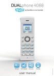
3.1
6.1
6.2
8.1
8.2
Sample Application Flowchart . . . . . . . . . . . . . . . . . . . . . . . . . . . . . . . . .
DIP Switch Settings for Download . . . . . . . . . . . . . . . . . . . . . . . . . . . . .
Power and Download Connections . . . . . . . . . . . . . . . . . . . . . . . . . . . . .
Typical DIP Switch Settings for SLC Operation . . . . . . . . . . . . . . . . .
SLC 500 Connections . . . . . . . . . . . . . . . . . . . . . . . . . . . . . . . . . . . . . . . .
3–1
6–1
6–2
8–1
8–2
Tables
1.A
1.B
Chapter Descriptions . . . . . . . . . . . . . . . . . . . . . . . . . . . . . . . . . . . . . . . . .
Related Publications . . . . . . . . . . . . . . . . . . . . . . . . . . . . . . . . . . . . . . . . .
1–1
1–2
iii
Chapter
A–B
1
Using This Manual
Chapter Objectives
Read this chapter to familiarize yourself with the rest of the manual. You will
learn about:
Contents of this manual
Intended audience
Related publications
Overview of this Manual
Use this manual to become familiar with the operation of the DTAM Plus
and the DTAM Plus Programming Software (Catalog No. 2707-NP). This
manual describes how to create, load and run a sample application.
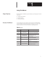
Table 1.A
Chapter Descriptions
Chapter
Title
1
Using this Manual
2
What You Need
3
Sample Application Overview
4
Installing DTAM Plus
Programming Software
5
Creating a Sample Application
6
Downloading the Application
7
SLC Application File
8
Running the Application
Purpose
Provides an overview of the manual.
Covers equipment and software needed
to create and run the sample application.
Briefly describes the sample application.
Tells how to install the DTAM Plus
Programming Software on your
personal computer.
Gives step-by-step instructions for
creating the sample application.
Explains how to transfer the application
from your personal computer to the
DTAM Plus.
Provides the SLC ladder program
required to run the sample application.
Describes how to run the sample
application with an SLC 500.
1–1
Chapter 1
Using This Manual
Intended Audience
No special knowledge is needed to create and run the sample DTAM Plus
application in this manual. You should understand the operation of an
SLC 500 and also how to enter and load a ladder logic program.
Conventions
This manual uses the following conventions:
Keys that you press on your personal computer keyboard are enclosed in
brackets [ ].
For example: [Esc] refers to the Escape key
[Return] refers to the carriage return key of your computer keyboard.
This key may appear on your keyboard as [Enter] or [ ].
Text strings that you enter on your computer keyboard are bold.
For example: Type 1 Pump Application and press [Return]
References to text that appears on your computer monitor are italicized.
For example: Pressing [Esc] returns you to the Edit File menu.
Related Publications
Table 1.B lists other publications you may require for additional reference.
Table 1.B
Related Publications
Publication / Catalog
Number
2707-800
DTAM Plus User Manual
2707-801
DTAM Plus Programming Manual
1747-800
1747-804
1747-NM002
1–2
Title
SLC 500 Fixed Hardware Style
Installation and Operation Manual
SLC 500 Modular Hardware Style
Installation and Operation Manual
Advanced Programming Software
User Manual
Chapter
A–B
2
What You Need
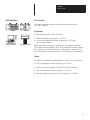
Chapter Objectives
This chapter describes the hardware and software needed to run the sample
application including:
Personal Computer
Requirements
Personal Computer
DTAM Plus
Programming Software
Personal Computer
DTAM Plus Programming Software
DTAM Plus Hardware
SLC Hardware with Programmer.
A personal computer is required to enter and load an application into the
DTAM Plus. The computer requirements are:
IBM PC/AT or 100% compatible
One or two floppy drives (720K minimum)
Hard drive is recommended and required if only one floppy drive
is present
640K of RAM
DOS 3.0 or later
Serial port on COM 1 or COM 2
Monochrome or color monitor
DTAM Plus Programming Software is used to create and download
applications to the DTAM Plus. You need DTAM Plus Programming
Software (Catalog No. 2707-NP) version 1.10 or later.
DPS Software
2–1
Chapter 2
What You Need
DTAM Plus Hardware
DTAM Plus
The sample application operates with the following versions of the
DTAM Plus:
2707-L8P1 and 2707-L8P2
2707-L40P1 and 2707-L40P2
2707-V40P1 and 2707-V40P2
2707-V40P2N
Communication Cables
To connect the DTAM Plus to an SLC and personal computer, you need the
following communication cables:
Network Interface Cable (Catalog No. 2707-NC1)
Upload/Download Cable (Catalog No. 2707-NC2)
Note: If constructing your own cables, use the cable diagrams in
Chapter 4 of the DTAM Plus User Manual.
Power Cord
You need a standard 3-prong power cord.
2–2
Chapter 2
What You Need
SLC Hardware
SLC Controller
The sample application operates with both fixed and modular style
SLC 500 Controllers.
SLC 501
SLC 500
Programmer
You can program the SLC 500 with either a:
APS Software on
Personal Computer
Hand-Held Terminal (Catalog No. 1747-PT1)
Advanced Programming Software (Catalog No. 1747-PA2E)
on a personal computer
Hand-Held Terminal
Note: APS software requires an Allen-Bradley T50 Industrial Terminal,
T47 Portable Terminal, IBM PC/AT or 100% compatible personal computer.
The computer requires 640K of RAM, a 10M hard drive, and DOS 3.0 or
later. APS software is provided on both 3 1/2 inch and 5 1/4 inch diskettes.
Cables
To connect the Hand-Held Terminal (HHT) to an SLC 500, use this cable:
SLC Communications Cable (Catalog No. 1747-C10)
To connect a personal computer to the SLC 500, use the following:
SLC Communications Cable (Catalog No. 1747-C10)
Personal Computer Interface Converter (Catalog No. 1747-PIC)
2–3
Chapter
A–B
3
Sample Application Overview
Chapter Objectives
This chapter gives a description of the sample application you are going to
enter. Understanding the function of the application will help you understand
the configuration instructions in Chapter 5.
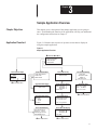
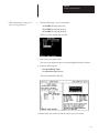
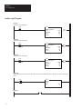
Application Flowchart
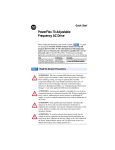
Figure 3.1 illustrates the sequence of operator screens that are displayed
using the sample application.
Figure 3.1
Sample Application Flowchart
❶ Screen #1 Main Menu
1
2
3
4
Screen #11 Bar Graph
Pump Speed
**** RPM
0
Pump Application
Tank 1 Parameters
Batch Recipes
Alarm Demo
Screen #20 Sub-Menu
1 Tank Temp Desired
2 Tank Level
3 Mixer Status
Screen #39 Security
RESTRICTED ACCESS
ENTER CODE
:
2000
❶ Back to Main Menu
Screen #23 Data Display
Mixer Status Mixer is OFF
Screen #27 Data Display
PRE:T4:30.PRE ***
T4:31.PRE ***
T4:32.PRE ***
Press Next
Screen #22 Data Display
Tank Level
**** Gallons
*** % Full
Press Next
Screen #28 Recipe
Download Batch Times
For Chocolate Chip?
Screen #21 Data Entry
Enter Desired Temp
Actual: *** Deg. C
Valid Range: 140-170
Desired:◆◆◆ Deg C.
Screen #29 Data Display
NEW: T4:30.PRE 5
T4:31.PRE 15
T4:32.PRE 25
Press Next
❶ Back to Main Menu
Screen #40 Data Entry
Enter 60 to
Simulate an Alarm
Advisor: 0
Data Entry: ◆◆
Screen #60 Alarm
Mixer OL is Tripped
03:19 Oct 28 92
Press ”Y” to Clear
❶ Back to Main Menu
Press ”Y” to Execute
❶ Back to Main Menu
3–1
Chapter 3
Sample Application Overview
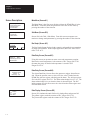
Screen Descriptions
1
2
3
4
Pump Application
Tank 1 Parameters
Batch Recipes
Alarm Demo
The Main Menu is the first screen displayed when the DTAM Plus is in the
Run Mode. From this menu an operator can select one of four items by
pressing the number of the selection.
1 Tank Temp Desired
2 Tank Level
3 Mixer Status
Sub-Menu (Screen #20)
Pump Speed
**** RPM
Bar Graph (Screen #11)
0
Screen #20 is the Tank 1 Sub-Menu. From this screen an operator can
monitor or change tank parameters by pressing the number of the selection.
2000
Enter Desired Temp
Deg. C
Actual: ***
Valid Range: 140-170
Desired: ◆◆◆
Enter 60 to
Simulate an Alarm
Advisor: 0
Data Entry: ◆◆
Tank Level
**** Gallons
*** % Full
Press Next
3–2
Main Menu (Screen #1)
The Bar Graph Screen displays both a numeric and graphical representation
of pump speed in RPM. In the sample application, this is the value of SLC
timer T4:11.ACC.
Data Entry Screen (Screen #21)
Using this screen, an operator can enter a new tank temperature setpoint.
Data for the actual temperature is the contents of SLC integer file N7:20.
Operator data entry for the desired temperature is stored in SLC
integer file N7:21.
Data Entry Screen (Screen #40)
The Alarm Data Entry Screen allows the operator to trigger Alarm Screen
#60. When the operator enters a value of 60, the value is loaded into the
DTAM Plus Advisor register which triggers the alarm. The Advisor register
file is the SLC register file N7:0. The alarm acknowledge bit is N7:1/1. The
alarm acknowledge bit is set when the alarm is acknowledged. The SLC
ladder program uses this bit to move the value 0 into the alarm register and
clear the alarm screen.
Data Display Screen (Screen #22)
Screen #22 simulates the tank fluid level in both gallons and percent full.
The gallons register reads the contents of SLC integer file N7:22.
The percent full register reads the contents of SLC integer file N7:23.
Chapter 3
Sample Application Overview
Mixer Status Mixer is OFF
Data Display Screen (Screen #23)
Screen #23 simulates the status of the Tank 1 mixer motor. The second line
displays the mixer status (Mixer ON or Mixer OFF) and is controlled by the
status of SLC bit B3:0/0.
Security Screen (Screen #39)
RESTRICTED ACCESS
ENTER CODE
:
Screen #39 restricts access to the recipe screens. The operator must enter
one of the following passwords:
1234 [
]
5678 [
]
1992 [
]
PRE:T4:30.PRE ***
T4:31.PRE ***
T4:32.PRE ***
Press Next
Data Display Screen (Screen #27)
Download Batch Times
For Chocolate Chip?
Recipe Screen (Screen #28)
Press ”Y” to Execute
Screen #27 displays the current timer preset values for the recipe. The
display registers are SLC timers T4:30.PRE, T4:31.PRE and T4:32.PRE.
Pressing [NEXT] advances the operator to screen #28.
Screen #28 is the Recipe Screen. The text prompts the operator to download
the timer values for the recipe. When the operator presses [Y], the new value
is loaded into the SLC timers and screen #29 is displayed.
NEW: T4:30.PRE 5
T4:31.PRE 15
T4:32.PRE 25
Press Next
Data Display Screen (Screen #29)
Mixer OL is Tripped
03:19 Oct 28 92
Alarm Screen (Screen #60)
Press ”Y” to Clear
Screen #29 displays the new timer preset values after the recipe is
downloaded.
The Alarm Screen indicates the date and time the alarm occurred. Pressing
[Y] clears the display and returns the operator back to the Main Menu.
3–3
Chapter
A–B
4
Installing DTAM Plus Programming Software
Chapter Objectives
This chapter shows how to install the DTAM Plus Programming Software
(Catalog No. 2707-NP) on your personal computer.
Checking
Available Memory
You should have at least 640K available RAM to run the DTAM Plus
Programming Software on your computer. Check the available RAM on
your computer using the CHKDSK command.
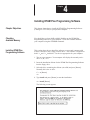
Installing DTAM Plus
Programming Software
This section shows how to install the software on a personal computer with
at least 1 hard drive and 1 floppy or micro drive. The software is supplied on
both 5 1/4 and 3 1/2 inch disks. Use the size appropriate for your computer.
1. Turn on your computer. Your computer will display the currently active
drive: A:, B:, or C:
2. Insert the installation diskette for the DTAM Plus Programming Software
into the floppy drive.
3. Select the drive containing the diskette (A: or B:) and press [Return].
Normally this is the A: drive.
C:> a: [Return]
A:>
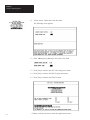
4. Type install and press [Return] to start the installation.
A:> install [Return]
The following screen appears:
4–1
Chapter 4
Installing DTAM Plus Programming Software
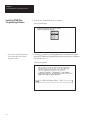
Installing DTAM Plus
Programming Software
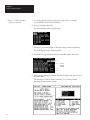
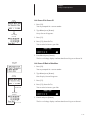
5. Press any key (other than [Esc]) to continue.
☞ You cannot install the software
on the same drive the Install
program resides.
6. Use the [] arrow keys to highlight the drive on which you want to
install the DTAM Plus Programming Software and then press [Return].
The default drive is C:
This screen displays.
This screen appears.
4–2
Chapter 4
Installing DTAM Plus Programming Software
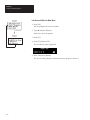
☞ You can specify another directory.
The Install program will create the
directory if it does not exist.
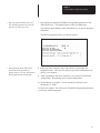
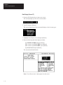
7. Press [Return] to install the DTAM Plus Programming Software in the
\DPS subdirectory. The Install program creates the subdirectory.
The Install program displays status information on your screen during the
installation.
The DPS Configuration Utility screen then appears:
☞ Press [Return] at the Video Type
and Comm Port questions to
prompt the user for this information
during application development.
8. Enter your name, company name, and software serial number (on
registration card). Also, enter the monitor type and communication port
used by your computer.
9. After responding to the above questions, you are asked to confirm the
configuration. Press [Return] to accept the configuration.
10. The installation is complete. You are returned to DOS at the new
subdirectory C: \DPS>.
Go to the next chapter. You will use the DTAM Plus Programming Software
to create the sample application.
4–3
Chapter
A–B
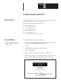
5
Creating a Sample Application
Chapter Objectives
This chapter provides step-by-step instructions on how to create the sample
application described in Chapter 3. It shows how to:
start the DTAM Plus Programming Software
create an application file
enter configuration data
create application screens
link application screens
create an alarm screen
save the application and exit the software
Starting DTAM Plus
To run the DTAM Plus Programming Software:
☞ If you installed the software in
another subdirectory, move to
that directory.
1. Verify that you are at the \DPS subdirectory where the software resides.
If you are not, enter cd DPS and press [Return].
C:\DPS>
2. Type DPS and press [Return] to start the program.
C:\DPS> DPS [Return]
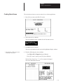
3. Specify whether you are using a color monitor. Enter Y or N.
4. The startup screen displays. It identifies the DPS version and licensed
owner. A phone support number is provided for your assistance.
5–1
Chapter 5
Creating a Sample Application
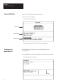
Starting DTAM Plus
To run the DTAM Plus Programming Software:
5. Press any key to continue.
The Opening Menu displays.
Menu Window
Operation Window
Information Window
You are now ready to create a file for your application.
Creating a New
Application File
The first thing you need to do is create a file in which to store
your application.
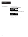
1. Press [Return] to select Edit Program File from the Opening Menu.
The following screen appears.
5–2
Chapter 5
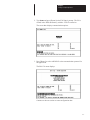
Creating a Sample Application
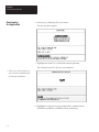
2. Type demo and press [Return] at the File Name? prompt. The file is
created in the \DPS subdirectory with the .CFG file extension.
The screen then displays communication options.
3. Press [Return] to select AB DH485 as the communication protocol for
the application.
The Edit File menu displays.
Continue to the next section to enter configuration data.
5–3
Chapter 5
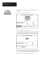
Creating a Sample Application
Entering DTAM Plus
Configuration Data
Now, you will enter configuration data for the DTAM Plus and
the SLC 500 processor.
1. Press [Return] to select DTAM Plus Configuration Data from the
Edit File menu.
The DPS Configuration menu appears.
2. Use the arrow [↓↑] keys to highlight DTAM Plus Advisor and
press [Return].
The DPS Advisor screen appears.
5–4
Chapter 5
Creating a Sample Application
3. Enter the data below and press [Return] after entering each item:
Read Register Number = N7:0
Write Register Number = N7:1
ACK Bit Number = 1
ACK Bit Polarity = 1
The screen should look like this.
4. Press [Esc] to save the data and return to the DPS Configuration menu.
5–5
Chapter 5
Creating a Sample Application
5. Use the arrow [↓↑] keys to highlight SLC Hardware Parameters and
press [Return].
The SLC 500 Configuration menu appears.
6. Press [Return] to select COM Port Setup.
The SLC COM Port Communication Parameters screen appears with the
current baud rate, parity and data bit settings displayed at the bottom.
The port must be set for 19200 baud rate, even parity, 8 data bits.
If necessary, modify the settings by selecting the appropriate menu item.
The screen then displays a list of options for the selected parameter. Use
the [↓↑] arrow keys to highlight the correct setting and press [Return].
7. Press [Esc] to return to the SLC 500 Configuration menu.
5–6
Chapter 5
Creating a Sample Application
8. Select DTAM Plus Node Address from the menu.
The DTAM Plus Node Address screen appears.
9. Enter 2 and press [Return] in the New Address field.
10. Press [Esc] to return to the SLC 500 Configuration menu.
5–7
Chapter 5
Creating a Sample Application
11. Select Advisor Update Rate from the menu.
The following screen appears.
12. Enter 1.00 and press [Return] in the Update Time field.
13. Press [Esc] to return to the SLC 500 Configuration menu.
14. Press [Esc] to return to the DPS Configuration menu.
15. Press [Esc] to return to the Edit File menu.
Continue to the next section to create the application screens.
5–8
Chapter 5
Creating a Sample Application
Creating
Application Screens
This section shows how to create the following application screens:
Main Menu (Screen 1)
Sub-Menu (Screen 20)
Data Display (Screens 22, 23, 27, 29)
Data Entry (Screens 21, 40)
Security (Screen 39)
Bar Graph (Screen 11)
Recipe (Screen 28)
Main Menu (Screen 1)
1. Highlight Screen Builder on the Edit File menu and press [Return].
The following screen appears.
Parameter
Window
Display
Window
Enter Text Here
Row/Column
Position of Cursor
Information
Window
Control
Window
2. Enter the following data for the Main Menu. Press [Return] after
entering each line:
1
2
3
4
Pump Application
Tank 1 Parameters
Batch Recipes
Alarm Demo
You have just created the Main Menu. It should look like this.
Continue to the next section to create the Sub-Menu.
5–9
Chapter 5
Creating a Sample Application
Sub-Menu (Screen 20)
1. Press the [F8] function key to start a new screen.
The screen prompts you for a new screen number.
2. Type 20 and press [Return]. This is the number for the Sub-Menu.
The Main Menu clears and the screen displays a list of screen types.
3. Press [Return] to select Sub-Menu Screen.
4. Enter the following data for the Sub-Menu. Press [Return] after
entering each line:
1 Tank Temp Desired
2 Tank Level
3 Mixer Status
You have just created the Sub-Menu. It should look like this.
Continue to the next section to create Data Display 22.
5–10
Chapter 5
Creating a Sample Application
Data Display (Screen 22)
1. Press the [F8] function key to start a new screen.
The screen prompts you for a new screen number.
2. Type 22 and press [Return]. This is the number for the first Data Display.
The screen clears the Sub-Menu and displays a list of screen types:
3. Use the [↓↑] keys to highlight Data Display Screen and press [Return].
4. Enter the following data in the display window:
Type Tank Level and press [Return]
Enter 6 spaces, type Gallons, press [Return]
Enter 4 spaces, type % Full, press [Return]
Type Press Next
The screen should look like this.
Note: You will now enter data registers for this screen.
5–11
Chapter 5
Creating a Sample Application
☞ Steps 5 – 9 define the data
register for Gallons.
5. Use the ["#][{] arrow keys to move the cursor to row 2, column 1
(6 spaces to the left of the word Gallons).
6. Press [F1] (Display Register).
The screen displays a list of register types.
7. Use the [↓↑] keys to highlight 16 Bit Signed Integer and press [Return].
The 16 Bit Signed Integer Display appears.
8. Use the arrow ["#] and [Return] keys to enter the register data below.
Arrows
indicate
changes
9. After pressing [Return] to enter the last line of register data, press [Esc] to
accept the data.
The data display window shows 5 asterisks (*****) before Gallons
indicating the data register position.
5–12
Chapter 5
Creating a Sample Application
☞ Steps 10 – 14 define the data
register for % Full.
10. Use the [] arrow keys to move the cursor to row 3, column 1
(4 spaces to the left of % Full).
11. Press [F1] (Display Register).
The screen displays a list of register types.
12. Use the [↓↑] keys to highlight 16 Bit Signed Integer and press [Return].
The 16 Bit Signed Integer Display appears.
13. Use the arrow [] and [Return] keys to enter the register data below.
Arrows
indicate
changes
14. After pressing [Return] to enter the last line of register data, press [Esc] to
accept the data.
The data display window shows 3 asterisks (***) before % Full
indicating the data register position.
Continue to the next section to create Data Display 23.
5–13
Chapter 5
Creating a Sample Application
Data Display (Screen 23)
1. Press the [F8] function key to start a new screen.
The screen prompts you for a new screen number.
2. Type 23 and press [Return].
The screen clears the previous screen and displays a list of screen types.
3. Highlight Data Display Screen and press [Return].
4. Type ^^ Mixer Status ^^ and press [Return] in the Data Display.
The screen should look like this.
Note: You will now enter register data for this screen.
5–14
Chapter 5
Creating a Sample Application
☞ Steps 5 – 9 define the data
register for Mixer Status
5. Use the ["#][{] arrow keys to move the cursor to row 2, column 4 of
the display window.
6. Press [F1] (Display Register).
The screen displays a list of register types.
7. Press [Return] to select Bit.
The Bit Display appears.
8. Use the arrow ["#] and [Return] keys to enter the following register data.
Arrows
indicate
changes
9. Press [Esc] after entering the register data.
The data display window shows 12 asterisks in row 2 indicating the
data register position.
Continue to the next section to create Data Display 27.
5–15
Chapter 5
Creating a Sample Application
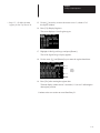
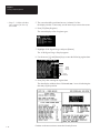
Data Display (Screen 27)
1. Press the [F8] function key to start a new screen.
The screen prompts you for a new screen number
2. Type 27 and press [Return].
The screen clears the previous screen and displays a list of screen types.
3. Highlight Data Display Screen and press [Return].
4. Enter the following data in the display window:
Type PRE:T4:30.PRE and press [Return]
Enter 4 spaces, type T4:31.PRE, press [Return]
Enter 4 spaces, type T4:32.PRE, press [Return]
Type Press Next and press [Return]
The screen should look like this.
Note: You will now enter 3 data registers for this screen.
5–16
Chapter 5
Creating a Sample Application
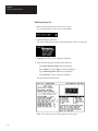
☞ Steps 5 – 9 define the data
register for line 1 of Screen 27.
5. Use the ["#][{] arrow keys to move the cursor to row 1, column 15 of
the display window.
6. Press [F1] (Display Register).
The screen displays a list of register types.
7. Highlight 16 Bit Signed Integer and press [Return].
The 16 Bit Signed Integer Display appears.
8. Use the arrow ["#] and [Return] keys to enter the following register data.
Arrows
indicate
changes
9. Press [Esc] after entering the register data.
The data display window shows 3 asterisks (***) in row 1 indicating the
data register position.
5–17
Chapter 5
Creating a Sample Application
☞ Steps 10 – 14 define the data
register for line 2 of Screen 27.
10. Use the [] arrow key to move the cursor to row 2, column 15 of
the display window.
11. Press [F1] (Display Register).
The screen displays a list of register types.
12. Highlight 16 Bit Signed Integer and press [Return].
The 16 Bit Signed Integer Display appears.
13. Use the arrow [] and [Return] keys to enter the following register data.
Arrows
indicate
changes
14. Press [Esc] after entering the register data.
The data display window shows 3 asterisks (***) in row 2 indicating the
data register position.
5–18
Chapter 5
Creating a Sample Application
☞ Steps 15 – 19 define the data
register for line 3 of Screen 27.
15. Use the [] arrow key to move the cursor to row 3, column 15 of
the display window.
16. Press [F1] (Display Register).
The screen displays a list of register types.
17. Highlight 16 Bit Signed Integer and press [Return].
The 16 Bit Signed Integer Display appears.
18. Use the arrow [] and [Return] keys to enter the register data below.
Arrows
indicate
changes
19. Press [Esc] after entering the register data.
The data display window shows 3 asterisks (***) in row 3 indicating the
data register position.
Continue to the next section to create data Display Screen 29.
5–19
Chapter 5
Creating a Sample Application
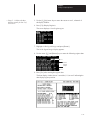
Data Display (Screen 29)
1. Press the [F8] function key to start a new screen.
The screen prompts you for a new screen number.
2. Type 29 and press [Return].
The screen clears the previous screen and displays a list of screen types.
3. Highlight Data Display Screen and press [Return].
4. Enter the following data in the display window:
Type NEW:T4:30.PRE and press [Return]
Enter 4 spaces, type T4:31.PRE, press [Return]
Enter 4 spaces, type T4:32.PRE, press [Return]
Type Press Next and press [Return]
The screen should look like this.
Note: You will now enter 3 data registers for this screen.
5–20
Chapter 5
Creating a Sample Application
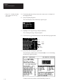
☞ Steps 5 – 9 define the data
register for line 1 of Screen 29.
5. Use the ["#][{] arrow keys to move the cursor to row 1, column 15 of
the display window.
6. Press [F1] (Display Register).
The screen displays a list of register types.
7. Highlight 16 Bit Signed Integer and press [Return].
The 16 Bit Signed Integer Display appears.
8. Use the arrow ["#] and [Return] keys to enter the following register data.
Arrows
indicate
changes
9. Press [Esc] after entering the register data.
The data display window shows 3 asterisks (***) in row 1 indicating the
data register position.
5–21
Chapter 5
Creating a Sample Application
☞ Steps 10 – 14 define the data
register for line 2 of Screen 29.
10. Use the [] arrow key to move the cursor to row 2, column 15 of
the display window.
11. Press [F1] (Display Register).
The screen displays a list of register types.
12. Highlight 16 Bit Signed Integer and press [Return].
The 16 Bit Signed Integer Display appears.
13. Use the arrow [] and [Return] keys to enter the following register data.
Arrows
indicate
changes
14. Press [Esc] after entering the register data.
The data display window shows 3 asterisks (***) in row 2 indicating the
data register position.
5–22
Chapter 5
Creating a Sample Application
☞ Steps 15 – 19 define the data
register for line 3 of Screen 29.
15. Use the [] arrow key to move the cursor to row 3, column 15 of
the display window.
16. Press [F1] (Display Register).
The screen displays a list of register types.
17. Highlight 16 Bit Signed Integer and press [Return].
The 16 Bit Signed Integer Display appears.
18. Use the arrow [] and [Return] keys to enter the register data below.
Arrows
indicate
changes
19. Press [Esc] after entering the register data.
The data display window shows 3 asterisks (***) in row 3 indicating the
data register position.
Continue to the next section to create Data Entry 21.
5–23
Chapter 5
Creating a Sample Application
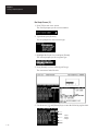
Data Entry (Screen 21)
1. Press the [F8] function key to start a new screen.
The screen prompts you for a new screen number.
2. Type 21 and press [Return].
The screen clears the previous screen and displays a list of screen types.
3. Highlight Data Entry Screen and press [Return].
4. Enter the following data for Data Entry Screen 21:
Type Enter Desired Temp and press [Return]
Type Actual: (5 spaces) Deg. C and press [Return]
Type Valid Range:140–170 and press [Return]
Type Desired: (4 spaces) and press [Return]
The screen should look like this.
Note: You will now enter 2 data registers for this screen.
5–24
Chapter 5
Creating a Sample Application
☞ Steps 5 – 9 define the data
display register for line 2 of
Screen 21.
5. Use the ["#][{] arrow keys to move the cursor to row 2, column 8 of
the display window.
6. Press [F1] (Display Register).
The screen displays a list of register types.
7. Highlight 16 Bit Signed Integer and press [Return].
The 16 Bit Signed Integer Display appears.
8. Use the arrow ["#] and [Return] keys to enter the following register data.
Arrows
indicate
changes
9. Press [Esc] after entering the register data.
The data display window shows 3 asterisks (***) in row 2 indicating the
data display register position.
5–25
Chapter 5
Creating a Sample Application
☞ Steps 10 – 14 define the data
entry register for line 4 of
Screen 21.
10. Use the ["#][{] arrow keys to move the cursor to row 4, column 9 of
the display window.
11. Press [F2] (Entry Register).
The screen displays a list of data entry register types.
12. Highlight 16 Bit Signed Integer and press [Return].
The 16 Bit Signed Integer Display appears.
13. Use the arrow ["#] and [Return] keys to enter the following register data.
Arrows
indicate
changes
Change
Automatically
14. Press [Esc] after entering the register data.
The data display window shows 3 diamonds (zzz) in row 4 indicating
the data entry register position.
Continue to the next section to create Data Entry Screen 40.
5–26
Chapter 5
Creating a Sample Application
Data Entry (Screen 40)
1. Press the [F8] function key to start a new screen.
The screen prompts you for a new screen number.
2. Type 40 and press [Return].
The screen clears the previous display and prompts you to enter a
screen type.
3. Highlight Data Entry Screen and press [Return].
4. Enter the following data in the display window:
Enter 4 spaces, type Enter 60 to and press [Return]
Enter 2 spaces, type simulate an alarm and press [Return]
Enter 4 spaces, type Advisor: 0 and press [Return]
Enter 1 space, type Data Entry: and press [Return]
The screen should look like this.
Note: You will now enter a data entry register for screen 40.
5–27
Chapter 5
Creating a Sample Application
☞ Steps 5 – 9 define the data
entry register for line 4 of
Screen 40.
5. The cursor should be positioned at row 4, column 13 of the
the display window. If necessary, use the arrow keys to move the cursor.
6. Press [F2] (Entry Register).
The screen displays a list of register types.
7. Highlight 16 Bit Signed Integer and press [Return].
The 16 Bit Signed Integer Display appears.
8. Use the arrow [] and [Return] keys to enter the following register data.
Arrows
indicate
changes
Change
Automatically
9. Press [Esc] after entering the register data.
The data display window shows 2 diamonds (zz) in row 4 indicating the
data entry register position.
Continue to the next section to create the Security Screen.
5–28
Chapter 5
Creating a Sample Application
Security Screen (39)
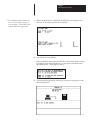
1. Press [F8] to start a new screen.
The screen prompts you for a new screen number.
2. Type 39 and press [Return].
You are prompted for a screen type.
3. Highlight Security Screen and press [Return].
This screen appears.
4. Enter the following access codes in the Security Codes window.
Code 1 = 1234 [Return]
Code 2 = 5678 [Return]
Code 3 = 1992 [Return]
5. Press [Esc] to accept the codes.
The screen should look like this. No other changes are required.
The application will use the default text in the window.
Continue to the next section to create a Bar Graph screen.
5–29
Chapter 5
Creating a Sample Application
Bar Graph Screen (11)
1. Press [F8] to start a new screen.
The screen prompts you for a screen number.
2. Type 11 and press [Return].
You are prompted to enter a screen type.
3. Highlight BarGraph Screen and press [Return].
The screen prompts you for a register type.
4. Press [Return] to select 16 Bit Signed Integer.
The screen now looks like this.
5. Use the arrow [] and [Return] keys to enter the following register data.
Arrows
indicate
changes
5–30
Chapter 5
Creating a Sample Application
6. Press [Esc] after entering the register data.
Notice how the values have been applied to the bar graph.
7. Enter the following text in the display window:
Type East Main Pump Speed.
Enter 5 spaces, type RPM and press [Return]
With the entered text, the display window looks like this.
8. Position the cursor at row 2, column 1 (5 spaces to the left of RPM).
9. Press [F1] (Display Bar Register).
You should see 4 asterisks (****) before RPM indicating a data register.
Continue to the next section to create Recipe Screen 28.
5–31
Chapter 5
Creating a Sample Application
Recipe Screen (28)
1. Press [F8] to start a new screen.
The screen prompts you for a new screen number.
2. Type 28 and press [Return].
The screen clears the bar graph and prompts you to select a screen type.
3. Highlight Recipe Screen and press [Return].
You are asked if the operator should be prompted to download the
recipe data.
4. Enter Y and press [Return].
You are asked to select a register type.
5. Press [Return] to select 16 Bit Signed Integer.
You are prompted to enter register data.
5–32
Chapter 5
Creating a Sample Application
☞ PRE automatically changes to 1
after pressing [Return].
6.
Enter the following 3 rows of recipe data.
T4:30.PRE [Return] 5 [Return]
T4:31.PRE [Return] 15 [Return]
T4:32.PRE [Return] 25 [Return]
The Recipe Data should look like this.
7. Press [Esc] to accept the data.
You are now prompted to enter text in the highlighted display window.
8. Enter the following text:
Download Batch Times
for Chocolate Chip [Return]
The screen should look like this.
Continue to the next section to link the screens you have created.
5–33
Chapter 5
Creating a Sample Application
Linking
Application Screens
This section shows how to link all the screens you have created.
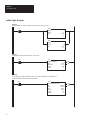
Main Menu Links
In this section, you will link screens 11, 20, 39 and 40 to the Main Menu.
Main Menu
Screen 11
Screen 20
Screen 39
Screen 40
1. Press [F8].
You are prompted for a screen number.
2. Type 1 and press [Return].
The Main Menu appears.
3. Press [F3] to link screens 11, 20, 39 and 40 to the Main Menu.
The Menu Item Linkage Display appears.
4. Enter the following screen links. Press [Return] after each entry.
5. Press [Esc] to save the links.
5–34
Chapter 5
Creating a Sample Application
Sub-Menu Links
In this section, you will link screens 21, 22 and 23 to the Sub-Menu.
Sub-Menu (Screen 20)
Screen 21
Screen 22
Screen 23
1. Press [F8].
You are prompted for a screen number.
2. Type 20 and press [Return].
The Sub-Menu screen appears.
3. Press [F3] to link screens 21, 22, and 23 to the Sub-Menu.
4. Enter the screen links as follows.
5. Press [Esc] to save the links.
5–35
Chapter 5
Creating a Sample Application
Main Menu
Screen 1
Link Screen 21 Back to Main Menu
1. Press [F8].
You are prompted for a screen number.
Previous Link
2. Type 21 and press [Return].
Data Entry Screen 21 appears.
Sub-Menu
Screen 20
3. Press [F3].
4. Press [F3] (Insert GoTo) again.
Previous Link
Data Entry
Screen 21
You are asked to insert a goto link.
5. Enter 1 and press [Return].
The Screen Linkage display confirms that Screen 21 returns to Screen 1.
Main Menu
Screen 1
Link Screen 22 Back to Main Menu
1. Press [F8].
You are prompted for a screen number.
Previous Link
Sub-Menu
Screen 20
2. Type 22 and press [Return].
Data Display Screen 22 appears.
3. Press [F3].
4. Press [F3] (Insert GoTo) again.
Previous Link
Data Display
Screen 22
You are asked to insert a goto link.
5. Enter 1 and press [Return].
The Screen Linkage display confirms that Screen 22 returns to Screen 1.
5–36
Chapter 5
Creating a Sample Application
Main Menu
Screen 1
Linking Screen 23 Back to Main Menu
1. Press [F8].
You are prompted for a screen number.
Previous Link
2. Type 23 and press [Return].
Data Display Screen 23 appears.
Sub-Menu
Screen 20
3. Press [F3].
4. Press [F3] (Insert GoTo).
Previous Link
You are asked to insert a goto link.
5. Enter 1 and press [Return].
Data Display
Screen 23
The Screen Linkage display confirms that Screen 23 returns to Screen 1.
Main Menu
Screen 1
Linking Screen 11 Back to Main Menu
1. Press [F8].
You are prompted for a screen number.
Previous Link
2. Type 11 and press [Return].
BarGraph Screen 11 appears.
BarGraph
Screen 11
3. Press [F3].
4. Press [F3] (Insert GoTo).
You are asked to insert a goto link.
5. Enter 1 and press [Return].
The Screen Linkage display confirms that Screen 11 returns to Screen 1.
5–37
Chapter 5
Creating a Sample Application
Security
Screen 39
Link Screen 39 to Screen 27
1. Press [F8].
You are prompted for a screen number.
2. Type 39 and press [Return].
Data Display
Screen 27
Security Screen 39 appears.
3. Press [F3].
4. Press [F3] (Insert GoTo).
You are asked to insert a goto link.
5. Enter 27 and press [Return].
The Screen Linkage display confirms that Screen 39 goes to Screen 27.
Data Display
Screen 27
Link Screen 27 to Screen 28
1. Press [F8].
You are prompted for a screen number.
2. Type 27 and press [Return].
Data Display Screen 27 appears.
Recipe
Screen 28
3. Press [F3].
4. Press [F3] (Insert GoTo).
You are asked to insert a goto link.
5. Enter 28 and press [Return].
The Screen Linkage display confirms that Screen 27 goes to Screen 28.
5–38
Chapter 5
Creating a Sample Application
Recipe
Screen 28
Link Screen 28 to Screen 29
1. Press [F8].
You are prompted for a screen number.
2. Type 28 and press [Return].
Data Display
Screen 29
Recipe Screen 28 appears.
3. Press [F3].
4. Press [F3] (Insert GoTo).
You are asked to insert a goto link.
5. Enter 29 and press [Return].
The Screen Linkage display confirms that Screen 28 goes to Screen 29.
Main Menu
Screen 1
Link Screen 29 Back to Main Menu
1. Press [F8].
You are prompted for a screen number.
2. Type 29 and press [Return].
Recipe
Screen 28
Data Display Screen 29 appears.
3. Press [F3].
4. Press [F3] (Insert GoTo).
Previous Link
You are asked to insert a goto link.
Data Display
Screen 29
5. Enter 1 and press [Return].
The Screen Linkage display confirms that Screen 29 goes to Screen 1.
5–39
Chapter 5
Creating a Sample Application
Main Menu
Screen 1
Link Screen 40 Back to Main Menu
1. Press [F8].
You are prompted for a screen number.
Previous Link
2. Type 40 and press [Return].
Data Entry screen 40 appears.
Data Entry
Screen 40
3. Press [F3].
4. Press [F3] (Insert GoTo).
You are asked to insert a goto link.
5. Enter 1 and press [Return].
The Screen Linkage display confirms that Screen 40 goes to Screen 1.
5–40
Chapter 5
Creating a Sample Application
Creating Alarm Screen
The section shows how to create an Alarm Screen for the application.
1. Press [Esc] to return to the Edit File menu.
2. Select Alarm Screen Builder.
You are prompted to enter a number for the first alarm screen.
3. Enter 60 and press [Return].
You are now prompted to enter text in the highlighted display window.
☞ Function key [F5] inserts time
and [F6] inserts date.
4. Enter the following text, time, and date:
Type Mixer OL is Tripped and press [Return]
Press [F5], enter 5 spaces, press [F6], press [Return]
The last line of text Press ”Y” to Clear cannot be changed.
The screen should look like this.
5–41
Chapter 5
Creating a Sample Application
Creating Alarm Screen
5. Press the [F3] key (Acknowledge).
The Alarm Acknowledge Register window appears.
6. Use the arrow [] and [Return] keys to enter the following data.
7. Press [Esc] after entering the data.
The Alarm Acknowledge window confirms the register data
you just entered.
Continue to the next section to edit the Background Monitor.
5–42
Chapter 5
Creating a Sample Application
Edit Background Monitor
You will now enter the Background Monitor to assign the alarm screen to a
bit that monitors alarm conditions. When this bit is set (turns ON), Alarm
Screen 60 will appear.
1. Press [Esc] to return to the Edit File menu.
2. Highlight Background Monitor and press [Return].
The Background Builder screen appears.
3. Press [Return] to select Background Register 1.
The following screen appears.
4. Press [Return] to select Bit.
You are prompted to enter Monitor Bit Register data.
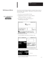
5. Enter the following data in the Monitor Bit Register window.
Enter 1 Here
After entering 60 and pressing [Return], the Alarm Screen
appears in the display window.
5–43
Chapter 5
Creating a Sample Application
Edit Background Monitor
6. Press [Esc] to accept the data.
You return to the Background Builder screen.
7. Press [Esc] to return to the Edit File menu.
You are now finished entering the sample application.
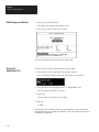
Saving the
Application File
You now need to save the application and return to DOS.
1. Press [Esc] to save the application and exit the software.
The screen displays the file name and path for the save operation.
2. Press [Return] to save the application to C:\DPS\DEMO.CFG.
You are returned to the Edit File menu.
3. Press [Esc].
You are asked if you want to exit to DOS.
4. Enter Y.
C:\DPS>
Now that you have entered and saved your application, you can download
the application to your DTAM Plus terminal. The next chapter shows how to
download an application.
5–44
Chapter
A–B
6
Downloading the Application
Chapter Objectives
This chapter describes how to download the sample application from your
computer to the DTAM Plus. It tells how to:
Set DTAM Plus DIP switches
Connect power and communication cables
Download the application
Download
DIP Switch Settings
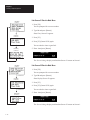
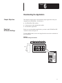
Before you can download an application, you must set the DTAM Plus DIP
switches as shown in Figure 6.1.
To access DIP switches, remove the plug from the access hole on the back of
the DTAM Plus.
Figure 6.1
DIP Switch Settings for Download
1
SW-1
Side View
2
3
ON
OFF
1
4
5
ON
2
OFF
OFF
3
6
ON
4
5
6
ON =
OPEN
6–1
Chapter 6
Downloading the Application
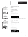
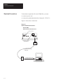
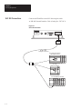
Download Connections
To download an application file to the DTAM Plus, you must:
connect a power cord
connect the upload/download cable (Catalog No. 2707-NC2)
Figure 6.2 shows these connections.
Figure 6.2
Power and Download Connections
Remote I/O With
RS-485 / RS-232 Communication Port
Power Connector
Remote I/O Connector
(Terminal Block)
Upload/Download Cable
Catalog No.
To Computer RS-232 Port
6–2
Chapter 6
Downloading the Application
Downloading
the Application
This section shows how to download the sample application from your
computer to the DTAM Plus.
1. Apply power to the DTAM Plus.
The following message appears in the window of the DTAM Plus.
Programming Mode
Waiting For Program
Upload / Download
If you do not see this message, check the DIP switch settings.
DIP Switch 1 must be in the Closed (ON) position.
2. Move to the /DPS subdirectory where the software resides.
C:\DPS>
3. Type dps and press [Return] to start the program.
C:\DPS>dps [Return]
. You will not see this prompt if
a monitor was specified during
installation.
4. Specify whether you are using a color monitor. Enter Y or N.
5. The startup screen displays. It identifies the DPS version and licensed
owner. A phone support number is provided for your assistance.
6–3
Chapter 6
Downloading the Application
Downloading
the Application
6. Press any key (other than [Esc]) to continue.
The Opening Menu appears.
7. Highlight Download File to DTAM Plus and press [Return].
The Communication Port Selection screen appears.
☞ This screen will not appear if
you selected a communication
port during installation.
8. Highlight the serial port on your computer that is connected to the
DTAM Plus (COMM 1 or COMM 2) and press [Return].
6–4
Chapter 6
Downloading the Application
☞ If a communication link does not
occur in 10 seconds, you get an
error message. Check DIP switch
settings and cable connections.
9. When communication is established, the following screen appears with
the name of the sample application file, DEMO.
10. Press [Return] to load DEMO.
If the Operating System of the file (DH-485) is different from the existing
Operating System in the DTAM Plus, you are asked to download a new
Operating System. If this happens, enter Y.
11. The download begins and the following screen shows the progress of the
download operation.
6–5
Chapter 6
Downloading the Application
Downloading
the Application
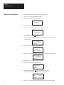
12. When the download is complete, you are returned to the Opening Menu.
13. Press [Esc] to exit the software.
14. Press [Y] to return to DOS.
You are now ready to run the application. Move on to the next chapter.
6–6
Chapter
A–B
7
SLC Application File
Chapter Objectives
This chapter provides the ladder logic program required to run the DTAM
Plus sample application.
Configuring the SLC 500
You can program an SLC 500 using either of the following:
Advanced Programming Software (APS) on a personal computer
Hand-Held Terminal
This manual does not provide instructions on how to program the SLC
controller. Refer to the User Manuals for the equipment you are using.
Included in this chapter is the logic program you need to enter.
Preloaded Values
To provide values for the sample program, the data below must be loaded
into the following SLC data files.
Address
N10:0
N10:10
N10:20
N10:30
N10:40
N10:50
N10:60
N10:70
N10:80
N10:90
N10:100
N10:110
N10:120
0
0
301
601
288
0
30
60
29
0
5
4
0
0
1
30
322
544
266
3
32
54
27
0
1
5
0
2
77
367
566
211
8
37
57
21
1
1
0
0
3
122
378
567
197
12
38
57
20
1
5
4
0
4
144
399
533
155
14
40
53
16
5
5
5
0
5
179
488
521
140
18
49
52
14
5
4
5
0
6
222
512
524
98
22
51
52
10
5
4
5
0
7
245
533
500
55
25
53
50
6
5
0
4
0
8
259
542
433
11
26
54
43
1
1
5
0
0
9
278
588
333
0
28
59
33
0
5
5
0
0
7–1
Chapter 7
SLC Application File
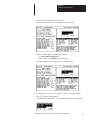
Ladder Logic Program
Rung 2:0
Reset the DTAM Plus Advisor registers during the first scan of the SLC 500.
MOV
S:1
15
MOVE
Source
Dest
0
N7:0
0
MOV
MOVE
Source
Dest
0
N7:1
3
Rung 2:1
This timer drives the SQO instructions once per second.
TON
T4:0
DN
TIMER ON DELAY
Timer
Time Base
Preset
Accum
T4:0
0.01
100
9
( EN )
( DN )
Rung 2:2
This sequencer simulates the gallons value for screen #22 (TANK LEVEL) in the DTAM Plus.
There are 40 decimal values pre-loaded into #N10:0
SQO
T4:0
DN
7–2
SEQUENCER OUTPUT
File
#N10:0
Mask
FFFF
Dest
N7:22
Control
R6:0
Length
40
Position
2
( EN )
( DN )
Chapter 7
SLC Application File
Rung 2:3
This sequencer provides the data to simulate the %FULL of the tank (Screen #22).
There are 40 decimal values preloaded into #N10:40
SQO
T4:0
DN
SEQUENCE OUTPUT
File
#N10:40
Mask
FFFF
Dest
N7:23
Control
R6:1
Length
40
Position
2
( EN )
( DN )
Rung 2:4
This rung simulates the temp preset value for screen #21. The operator keys in the desired temp ranging from 140 to 170.
The DTAM Plus writes this value directly to N7:21. This rung then moves the entered value to N7:20 (Data Display Register).
The data display register simulates the actual temp.
MOV
MOVE
Source
Dest
N7:21
144
N7:20
144
Rung 2:5
This SQO provides the bit values that simulate the Mixer (Screen #23)
SQO
T4:0
DN
SEQUENCER OUTPUT
File
#N10:80
Mask
0007
Dest
B3:0
Control
R6:2
Length
40
Position
2
( EN )
( DN )
Rung 2:6
Free running timer provides variable data for Bar Graph screen #11.
T4:11
DN
TON
TIMER ON DELAY
Timer
Time Base
Preset
Accum
T4:11
0.01
2000
35
( EN )
( DN )
7–3
Chapter 7
SLC Application File
Ladder Logic Program
Rung 2:7
Batch recipe free running timer.
TON
T4:30
TIMER ON DELAY
Timer
Time Base
Preset
Accum
DN
T4:30
0.01
100
22
( EN )
( DN )
Rung 2:8
Batch recipe free running timer.
TON
T4:31
TIMER ON DELAY
Timer
Time Base
Preset
Accum
DN
T4:31
0.01
500
28
( EN )
( DN )
Rung 2:9
Batch recipe free running timer.
TON
T4:32
TIMER ON DELAY
Timer
Time Base
Preset
Accum
DN
T4:32
0.01
300
14
( EN )
( DN )
Rung 2:10
When the alarm ACK bit N7:1/1 is true, the value ”0” is moved to the DTAM Plus Advisor register. This clears and resets the
alarms.
N7:1
MOV
MOVE
Source
Dest
1
Rung 2:11
END
7–4
0
N7:0
0
Chapter
A–B
8
Running the Application
Chapter Objectives
This chapter shows how to:
Set DTAM Plus DIP Switches
Connect the DTAM Plus to an SLC Controller
Run the application
DTAM Plus DIP
Switch Settings
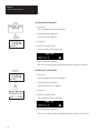
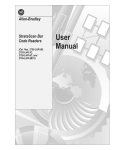
To run the application with an SLC 500, set the DTAM Plus DIP switches as
shown in Figure 8.1.
Access DIP switches by removing the plug from the access hole on the back
of the DTAM Plus.
Figure 8.1
Typical DIP Switch Settings for SLC Operation
1
SW-1
2
ON
OFF
3
4
ON
5
6
ON
OFF
OFF
Side View
1
2
3
4
5
6
ON =
OPEN
Back of DTAM Plus
8–1
Chapter 8
Running the Application
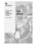
SLC 500 Connections
Connect the DTAM Plus to the SLC 500 using this cable:
DH-485 Network Interface Cable (Catalog No. 2707-NC1)
Figure 8.2
SLC Cable Connection
DH-485 Cable
Catalog No. 2707-NC1
SLC 500 Fixed Controller
with Expansion Rack
ÊÊ
ÊÊ
SLC 500
Fixed I/O Controller
SLC 500 Modular Controller
8–2
Chapter 8
Running the Application
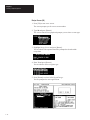
Running the Application
You are now ready to run the sample application.
1. Cycle power to the DTAM Plus to activate the new DIP switch settings.
2. The DTAM Plus displays a series of diagnostic tests, enters run mode,
loads the application and then displays the Main Menu of the application.
1
2
3
4
Pump Application
Tank 1 Parameters
Batch Recipes
Alarm Demo
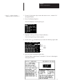
3. Press the [1] key on the DTAM Plus.
A Bar Graph display appears showing the RPM of the pump. The Bar
Graph and data display should change as the data in the SLC register
T4:11.2 changes.
East Main Pump Speed
1276 RPM
0
2000
4. Press the [NEXT] or [PREV] key to display the Main Menu.
5. Press [2] to access the Sub-Menu.
1 Tank Temp Desired
2 Tank Level
3 Mixer Status
6. Press [1] to enter a new tank temperature.
Enter Desired Temp
Actual:150 Deg. C.
Valid Range:140–170
Desired:_
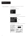
7. Enter a value of 200 and press the [ ] key.
An Input Error appears because the value is out of the 140–170 range.
** Input Error **
LOW LIM
HIGH LIM
140
170
Presss ”Y” to Reenter
8. Press Y. You are prompted to enter a new temperature.
9. Enter 150 and press [
1
2
3
4
]. You return to the Main Menu.
Pump Application
Tank 1 Parameters
Batch Recipes
Alarm Demo
10. Press the [2] key to access the Sub-Menu.
11. Press [2] again to display the tank level parameters.
Tank Level
33 Gallons
10% Full
Press Next
8–3
Chapter 8
Running the Application
Running the Application
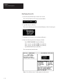
12. Press the [NEXT] key to return to the Main Menu.
13. Press [2] to select the Sub-Menu again.
14. Press [3] to display the mixer status.
^^ Mixer Status ^^
Mixer is ON
15. Press [NEXT] to return to the Main Menu.
16. Press [3]. You are prompted to enter an access code.
*RESTRICTED ACCESS*
ENTER CODE
:
17. Enter 1234 and press [ ] key.
The DTAM Plus validates the password and then displays the current
register values.
PRE: T4:30.PRE 100
T4:31.PRE 500
T4:32.PRE 300
Press Next
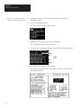
18. Press [NEXT] to display the Recipe Screen.
Download Batch Times
for Chocolate Chip
Press ”Y” to Execute
19. Press [Y] to downloaded the recipe with the new values that display.
NEW: T4:30.PRE 5
T4:31.PRE 15
T4:32.PRE 25
Press Next
20. Press [NEXT] to return to the Main Menu.
21. Press [4] to display the Alarm Screen.
Enter 60 to
simulate an alarm
Advisor: 0
Data Entry:
22. Enter 60 and press the [ ] key to simulate an alarm.
The alarm LED flashes and the alarm message appears.
03:2
Mixer OL is Tripped
Nov 08 92
PRESS ”Y” TO CLEAR
23. Press [Y] to return clear the message and return to the Main Menu.
8–4
Rockwell Automation helps its customers receive a superior return on their investment by bringing
together leading brands in industrial automation, creating a broad spectrum of easy-to-integrate
products. These are supported by local technical resources available worldwide, a global network
of system solutions providers, and the advanced technology resources of Rockwell.
Worldwide representation.
Argentina • Australia • Austria • Bahrain • Belgium • Bolivia • Brazil • Bulgaria • Canada • Chile • China, People’s Republic of • Colombia • Costa Rica • Croatia • Cyprus
Czech Republic • Denmark • Dominican Republic • Ecuador • Egypt • El Salvador • Finland • France • Germany • Ghana • Greece • Guatemala • Honduras • Hong Kong
Hungary • Iceland • India • Indonesia • Iran • Ireland • Israel • Italy • Jamaica • Japan • Jordan • Korea • Kuwait • Lebanon • Macau • Malaysia • Malta • Mexico • Morocco
The Netherlands • New Zealand • Nigeria • Norway • Oman • Pakistan • Panama • Peru • Philippines • Poland • Portugal • Puerto Rico • Qatar • Romania • Russia • Saudi
Arabia • Singapore • Slovakia • Slovenia • South Africa, Republic of • Spain • Sweden • Switzerland • Taiwan • Thailand • Trinidad • Tunisia • Turkey • United Arab Emirates
United Kingdom • United States • Uruguay • Venezuela
Rockwell Automation Headquarters, 1201 South Second Street, Milwaukee, WI 53204-2496 USA, Tel: (1) 414 382-2000 Fax: (1) 414 382-4444
Rockwell Automation European Headquarters, Avenue Hermann Debroux, 46, 1160 Brussels, Belgium, Tel: (32) 2 663 06 00, Fax: (32) 2 663 06 40
Rockwell Automation Asia Pacific Headquarters, 27/F Citicorp Centre, 18 Whitfield Road, Causeway Bay, Hong Kong, Tel: (852) 2887 4788, Fax: (852) 2508 1846
World Wide Web: http://www.ab.com
Publication 2707-802 – January 1993
40062-271-01(A)
Copyright 1993 Allen-Bradley Company, Inc. Printed in USA