1
FTS500 GPS
Disciplined Clock
User Manual
Available at Digi-Key
www.digikey.com
Bulletin
Revision
Date
SG183-UM
00
20 July 2012
TABLE OF CONTENTS
1. DESCRIPTION.................................................................................................................................................................4-5
1.1 Introduction.................................................................................................................................................... 4
1.2 Global Positioning System.............................................................................................................................. 5
1.3 GPS Positioning and Timing........................................................................................................................... 5
1.4 GPS Positioning and Timing and Timing Solution Accuracy.......................................................................... 5
2. S
PECIFICATION..............................................................................................................................................................6-9
2.1 Operating Specifications . ............................................................................................................................. 6
2.2 Absolute Maximum Ratings............................................................................................................................ 6
2.3 Phase Noise................................................................................................................................................... 7
2.4 Xenith TBR Modified Allan Deviation.............................................................................................................. 8
2.5 Xenith TBR Wander Generation Plot............................................................................................................... 8
2.6 Block Diagram................................................................................................................................................ 9
3. FTS500 Xenith TBR Front Panel.....................................................................................................................................10
3.1 RS232 Interface............................................................................................................................................ 10
4. SIGNAL DESCRIPTION...................................................................................................................................................11
4.1 Power............................................................................................................................................................ 11
4.2 Antenna Connection..................................................................................................................................... 11
4.3 Serial Port..................................................................................................................................................... 11
4.4 1 PPS Output................................................................................................................................................ 11
4.5 Frequency Output........................................................................................................................................ 11
4.6 LED Indicators.............................................................................................................................................. 11
4.7 Master Reset................................................................................................................................................ 11
5. FEATURES........................................................................................................................................................................12
5.1 Stationary Timing Receiver........................................................................................................................... 12
5.2 Frequency Output and 1PPS Phase Alignment............................................................................................ 12
6. OPERATING INSTRUCTIONS..........................................................................................................................................12
7. COMMUNICATIONS PROTOCOLS.............................................................................................................................13-22
7.1 Approved NMEA Messages......................................................................................................................... 13
7.1.1 GPGLL - Geographic position, Lat/Lon............................................................................................... 13
7.1.2 GPGGA - GPS fix data........................................................................................................................ 14
7.1.3 GPGSA - GPS DOP and Active satellites............................................................................................ 14
7.1.4 GPGSV - GPS Satellites in View.......................................................................................................... 15
7.1.5 GPRMC - Recommended Minimum data............................................................................................ 15
7.1.6 GPVTG - Course over ground and Ground speed.............................................................................. 16
7.2 Proprietary NMEA Messages....................................................................................................................... 16
7.2.1 POLYT - Time of Day........................................................................................................................... 16
7.2.2 POLYP- Position Data.......................................................................................................................... 17
7.2.3 POLYS - Satellite Status....................................................................................................................... 18
7.2.4 POLYI, Additional Information Message.............................................................................................. 18
7.3 Command Format *...................................................................................................................................... 19
7.3.1 PRTH<Q|R>, VERS: Software Version................................................................................................. 19
7.3.2 PRTH<Q|S|R>, DYNA: RECEIVER DYNAMICS................................................................................... 20
7.3.3 PRTH<Q|S|R>, ITIM: INITIALISE TIME AND DATE.............................................................................. 20
7.3.4 PRTH<Q|S|R>, RSET: RE-SET THE RECEIVER................................................................................... 21
7.3.5 PRTH<Q|S|R>, ILLH: INITIALIZED LAT, LONG, HEIGHT POSITION................................................... 21
7.3.6 PRTH<Q|S|R>, MMSV: MIN & MAX SATELLITES FOR A POSITION SOLUTION................................ 22
7.3.7 PRTH<Q|S|R>, ELVM: SATELLITE ELEVATION MASK........................................................................ 22
SG183 FTS500 Xenith TBR User Manual
Page 2
Rev: 00
Date: 07/20/12
© Copyright 2012 The Connor-Winfield Corp. All Rights Reserved Specifications subject to change without notice
TABLE OF CONTENTS
8.NMEA and UART Configuration Details.........................................................................................................................23
8.1 NMEA Configuration Query ($PRTHQ, U1CM):........................................................................................... 23
8.2 NMEA Configuration Set ($PRTHS,U1CM):.................................................................................................. 23
8.3 UART Configuration Query ($PRTHQ, U1CM):............................................................................................ 23
8.4 UART Configuration Set ($PRTHQ,U1CM)................................................................................................... 23
APPENDIX 1 - Glossary.................................................................................................................................................24-27
APPENDIX 2 - Contact Details............................................................................................................................................26
APPENDIX 3 - World Wide Web...........................................................................................................................................26
Revision History..................................................................................................................................................................27
SG183 FTS500 Xenith TBR User Manual
Page 3
Rev: 00
Date: 07/20/12
© Copyright 2012 The Connor-Winfield Corp. All Rights Reserved Specifications subject to change without notice
1. DESCRIPTION
1.1 Introduction
The FTS500 Xenith TBR (Time Base Reference) is the ultimate partner for your DVB/DAB, wireless communications, timestamping or any other “timing-vital” application.
The Xenith TBR module is a GPS driven, mixed-signal phase lock loop, providing a 1 PPS CMOS output and generating
a 10 MHz SINE output from an intrinsically low jitter voltage controlled crystal oscillator (VCXO). The 10 MHz output is
disciplined from an on-board GPS receiver, which drives the long term frequency stability. The on board GPS receiver at the
core of the Xenith TBR is the highly successful and well established CW25 timing receiver. This GPS engine along with a dual
oven system provides the highest quality timing and synchronization signals combined with superb holdover characteristics.
The unit is housed in a 106x125x56mm stylishly designed, strong aluminum enclosure. The 10 MHz and 1 PPS signal
are available on BNC connectors. The antenna input is also a BNC connector and will operate a 5V active antenna. The Xenith
TBR requires this antenna to placed outdoors for best stability and consistent performance. The Xenith TBR communicates via
RS232 and can be operated and monitored through only NMEA currently supported or TSIP protocol with optional software.
The user can observe the status of the unit, time of day, position and satellite quality information via either of the two protocols.
The unit has a wide DC power input range, between 8 and 28VDC, via a secure 2 pin Molex type connector. Accessories such
as: AC Mains adaptor (all regions), antenna cable, high performance outdoor antenna and serial cable are available as a kit or
can be individually purchased as needed.
Key features include:
•
•
•
•
•
•
•
•
•
•
•
•
•
Stratum 1 Time Source
G.811 Compliant (GPS Locked)
Meets ESTI PRC Wander Generation Mask (GPS Locked)
Phase Locked 10 MHz Output
Low Phase Noise
Precise 1 PPS Output
Serial Input/Output Port (GPS Receiver)
Master Reset
8V-28V Power Supply
Commercial Temp (0-70° C)
Mechanical Dimensions: 106 x 125 x 56mm (not including connectors)
Aluminum Housing
Fixed Position Unit
This document provides information on the Hardware and Software elements of the FTS500.
Key information includes:
• Specification
• Physical Characteristics
• Signal Descriptions
• Features
• Application Information
The FTS500 is available in a number of standard software builds, depending on the application for which it is to be
used. In special cases, the FTS500 may be supplied with a slightly different hardware build. The specifications in
this manual refer to the standard builds.
SG183 FTS500 Xenith TBR User Manual
Page 4
Rev: 00
Date: 07/20/12
© Copyright 2012 The Connor-Winfield Corp. All Rights Reserved Specifications subject to change without notice
1. DESCRIPTION continued
1.2Global Positioning System (GPS)
The Global Positioning System (GPS) is a military satellite based navigation system developed by the U.S. Department of Defense, which is made freely available to civil users. Civilian use of GPS is made available at the user’s own risk, subject to the
prevailing DoD policy or limitations, and to individuals understanding of how to use the GPS.
In today’s satellite constellation there are a minimum of 24 operational satellites (plus several operational spares) in 6 orbital
planes, at an altitude of about 22,000 km. The GPS system can give accurate 3D position, velocity, time, and frequency, 24
hours a day, anywhere around the world.
GPS satellites transmit a code for timing purposes, and also a ‘Navigation message’, which includes their exact orbital lo¬cation
and system integrity data. Receivers use this information, together with data from their internal almanacs, to precisely establish
the satellite location. The receiver determines position by measuring the time taken for these signals to arrive. At least three
satellites are required to determine latitude and longitude if your altitude is known (e.g. a ship at sea), and at least a fourth to
obtain a 3D fix.
1.3GPS Positioning and Timing
The FTS500 Receiver must be able to see at least 4 satellite vehicles (SV’s) to obtain a 3D position fix. After the FTS500 has a
3D fix, a 10-minute auto-survey is started to more precisely determine the fixed position of the antenna. When the 10-minute
auto-survey completes, the FTS500 fixes its position solution and is able to provide a timing solution with increased accuracy.
Also with the auto-survey complete, the FTS500 is able to maintain a GPS fix under reduced signal conditions while tracking
as few as 1 SV. However, the receiver’s antenna must have a clear view of the sky for optimum timing performance. While the
FTS500 is designed to maintain a GPS lock in reduced signal conditions, like shallow indoor environments, the published specifications can only be accomplished with an antenna with a clear view of the sky.
To measure the range from the satellite to the receiver, two criteria are required: signal transmission time, and signal reception
time. All GPS satellites have several atomic clocks that keep precise time and these are used to time-tag the message (i.e. code
the transmission time onto the signal) and to control the transmission sequence of the coded signal. The receiver has an internal
clock to precisely identify the arrival time of the signal. Transit speed of the signal is a known constant (the speed of light), therefore:
distance = time x speed of light.
Once the receiver calculates the range to a satellite, it knows that it lies somewhere on an imaginary sphere whose radius is
equal to this range. If a second satellite is then found, a second sphere can again be calculated from this range information. The
receiver will now know that it lies somewhere on the circle of points produced where these two spheres intersect.
When a third satellite is detected and a range determined, a third sphere would intersect the area formed by the other two. This
intersection occurs at two points. The correct point is apparent to the user, who will at least have a very rough idea of position. A
fourth satellite is then used to synchronize the receiver clock to the satellite clocks.
In practice, just 4 satellite measurements are sufficient for the receiver to determine a position, as one of the two points will be
unrealistic (possibly many kilometers out into space).
This assumes the satellite and receiver timing is identical. In reality, when the FTS500 Receiver compares the incoming signal
with its own internal copy of the code and clock, the two will no longer be synchronized. Timing errors in the satellite clocks,
the receiver clock, and other anomalies, mean that the measurement of the signals transit time is in error. This effectively, is a
constant for all satellites, since each measurement is made simultaneously on parallel tracking channels. Because of this, the
resulting ranges calculated are known as “pseudo-ranges”.
To overcome these errors, the FTS500 Receiver then matches or “skews” its own code to become synchronous with the satellite signal. This is repeated for all satellites in turn, thus measuring the relative transit times of individual signals. By accurately
knowing all satellite positions, and measuring the signal transit times, the antenna’s position can be accurately determined. The
FTS500 then uses the local clock drift and bias terms of the GPS solution to produce GPS disciplined time and frequency references (1PPS and 10 MHz outputs).
1.4 GPS Position and Timing Solution Accuracy
Dilution Of Precision (DOP) is a measure of the satellite geometry, and is an indicator of the potential quality of the solutions. The
lower the numerical value, the better the potential accuracy (for example, a PDOP below 3 indicates good satellite geometry).
The following DOP terms are computed by FTS500:
HDOP Horizontal Dilution of Precision (Latitude, Longitude)
VDOP Vertical Dilution of Precision (Height)
TDOP Time Dilution of Precision (Timing errors)
PDOP Position Dilution of Precision (3-D positioning)
GDOP Geometric Dilution of Precision (3-D position & Time)
Estimated accuracy = DOP x measurement accuracy
While each of these terms can be individually computed, they are formed from co-variances, and are not independent of each
other. For example, a high PDOP will cause receiver position errors that will eventually result in increased clock errors. The
FTS500 is able to reduce this effect by more accurately determining the fixed antenna position with the auto-survey.
SG183 FTS500 Xenith TBR User Manual
Page 5
Rev: 00
Date: 07/20/12
© Copyright 2012 The Connor-Winfield Corp. All Rights Reserved Specifications subject to change without notice
2. SPECIFICATION
2.1 Operating Specifications
Parameter
Notes
Minimum
Typical
Maximum
Units
Mechanical Dimensions
106 x 125 x 56
mm
Main Supply Voltage
8
24
28
Vdc
Operating Temperature
0
70
°C
Power Consumption (initial power up)
-
11.3
12
Watts
Power Consumption (continuous mode)
-
4.41
5
Watts
GPS
Voltage for Active Antenna (Vdc)
4.8
5.0
5.1
V
Current Draw for Antenna -
-
45
mA
GPS Channels -
12
-
Tracking Sensitivity -
156
-
dBm
Acquisition Sensitivity -
155
-
dBm
GPS Acquisition Time 150
sec
Update Rate 1
Hz
I/O Communications
Protocol
NMEA 0183, TSIP
RS232
Timing Signals -1PPS CMOS
Pulse Amplitude Electrical
3.3
Vdc
Pulse Width 100
uS
Accuracy (RMS)
30
nS
Timing Signals -10Mhz Sine wave
Impedance 50
Ohm
Power 9
dBm
Total Harmonic Distortion
2.2%
Compliant Specifications
.811 Compliant (GPS Locked)
G
G.812 Holdover Compliant ESTI PRC Wander Mask(GPS Locked)
Table 1 FTS500 Specification
2.2 Absolute Maximum Ratings
Parameter
Minimum
Maximum
Units
N otes
Input DC Voltage
-0.3
30.5
V
1
Operating Temperature
-30
80
°C
1
Table 2 Absolute Maximum Ratings
NOTES:
1.Stresses beyond those listed under “Absolute Maximum Rating” may cause permanent damage to the module. These are stress ratings only
and functional operation of the device at these or any other conditions beyond those indicated under “Operating Specifications” is not implied.
Exposure to absolute maximum rated conditions for extended periods may affect device reliability.
SG183 FTS500 Xenith TBR User Manual
Page 6
Rev: 00
Date: 07/20/12
© Copyright 2012 The Connor-Winfield Corp. All Rights Reserved Specifications subject to change without notice
2. SPECIFICATION continued
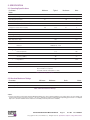
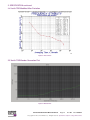
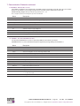
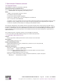
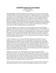
2.3 Phase Noise
Offset Frequency (Hz)
Typical (dBc / Hz)
10
-115
100
-135
1k
-143
10k
-148
100k
-152
1M
-153
Xenith TBR 10 MHz SINE Output
Figure 1 Phase Noise
SG183 FTS500 Xenith TBR User Manual
Page 7
Rev: 00
Date: 07/20/12
© Copyright 2012 The Connor-Winfield Corp. All Rights Reserved Specifications subject to change without notice
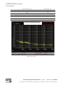
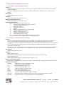
2. SPECIFICATION continued
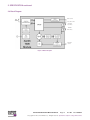
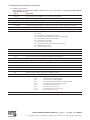
2.4 Xenith TBR Modified Allan Deviation
Figure 1 Phase Noise
2.5 Xenith TBR Wander Generation Plot
Figure 2 Wander Plot
SG183 FTS500 Xenith TBR User Manual
Page 8
Rev: 00
Date: 07/20/12
© Copyright 2012 The Connor-Winfield Corp. All Rights Reserved Specifications subject to change without notice
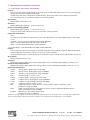
2. SPECIFICATION continued
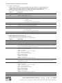
2.6 Block Diagram
SERIAL OUTPUT
1 PPS CMOS OUTPUT
HOLDOVER
LOCK STATUS
ANTENNA
FAULT STATUS
10 MHz SINE
OUTPUT
Figure 4 Block Diagram
SG183 FTS500 Xenith TBR User Manual
Page 9
Rev: 00
Date: 07/20/12
© Copyright 2012 The Connor-Winfield Corp. All Rights Reserved Specifications subject to change without notice
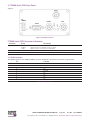
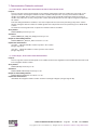
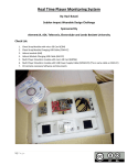
3. FTS500 Xenith TBR Front Panel
Figure 5
RF-IN
DC
POWER
1 PPS
LOCK
-
ANT
10 MHz
RS232
+
Figure 2 FTS500 Front Panel
FTS500 Xenith TBR Connector Information
Connector
Name
BNC
RF-IN
10 MHz
1 PPS
Antenna input, Provides 5Vdc for active antenna (Max current draw 45mA)
High performance 10 MHz reference signal
High accuracy 1 pulse per second signal
Description
DB9-F
RS232
ASCII/NMEA or TSIP for monitoring and configuration
Molex
Power
8-28vdc Input, mates with 2-Way Mini-Fit Jr Molex connector, Mating PN: 39-01-3022
3.1RS232 Interface
The RS232 Interface to the FTS500 is a DB9-F connector. The details of the interface connections are given below.
Pin
Function
1
2
3
4
5
6
7
8
NC
TX
RX
NC
Ground
NC
NC NC
9
NC
Table 4 RS232 Interface
SG183 FTS500 Xenith TBR User Manual
Page 10
Rev: 00
Date: 07/20/12
© Copyright 2012 The Connor-Winfield Corp. All Rights Reserved Specifications subject to change without notice
4. INTERFACES
4.1Power
The FTS500 is powered through the Molex power connector with 8 to 26 VDC. The FTS500 kit includes a DC adapter with the
correct voltage and connector.
4.2 Antenna Connection
The antenna is connected using the female BNDC connector marked RF-IN. If the necessary antenna has a different connector,
a suitable adaptor is required. The FTS500 provides 5VDC to the antenna jack to power active antennas. A maximum of 45mA
should be drawn from the antenna power to prevent the overcurrent protection int he FTS500 from activating.
4.3Serial Port
The RS232 serial port is available on the DB9-F connector. The FTS500 outputs NMEA 0138 sentences through the serial port
as well as accepts configuration commands. A detailed description of the communications protocol is given in Section 8.
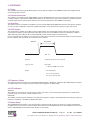
4.41PPS Output
The 1PPS output is available on the BNC connector labeled 1PPS. The 1PPS interface outputs a precise pulse with respect
to UTC time. The signal is acctive high with the rising edge synchronous (25 ns RMS) to the UTC second and has a width of
100us. Alternate pulse widths may be accommodated with custom firmware. Please consult the factory.
For the 1PPS output to be valid the receive must have a valid position fix and have received the UTC-GPS correction parameter
from the satellites. This may take up to 12.5 minutes from a cold start.
Risetime
Pulsewidth
Pulse width:
100 Sec
Risetime:
maximum 10 nSec (2 metre std. lead)
Synch. to UTC:
rising edge
+/- 30 nSec (GDOP, 3.0, no S/A)
Output:
+ 3.3V Volt nominal
(Vhigh > 3.0 v at 6mA out,
Vlow < 0.33 v at 6mA sink)
4.5Frequency Output
The frequency output on the BNC connector labeled 10 MHz provides a 10 MHz AC coupled low jitter SINE output. The frequency output provides a recise frequency reference that is phase aligned to the 1PPS output..
4.6LED Indicators
ANT LED
This indicator is Green when the current from the antenna connection is in the normal range and Red when an undercurrent
(open DC circuit) or overcurrent (>45mA) condition occurs.
LOCK LED
This indicator is Green when the GPS status is locked and the frequency output is valid and Red when the frequency output is in
holdover. If no holdover is available, the LOCK LED is dark.
4.7Master Reset
The FTS500 Master Reset button can be activated with a small tool through the hold near the power connector. Resetting the
FTS500 may be ncecessary if the antenna remains disconnected for an extended period of time. The FTS500 can also be reset
with the $PRTHS,RSET serial command. See Section 7.3.4 for details.
SG183 FTS500 Xenith TBR User Manual
Page 11
Rev: 00
Date: 07/20/12
© Copyright 2012 The Connor-Winfield Corp. All Rights Reserved Specifications subject to change without notice
5. FEATURES
5.1 Stationary Timing Receiver
The FTS500 operates in a survey and position hold mode which allows increased accuracy for timing applications. The
FTS500’s default dynamics setting is 1 and changes to 0 after a 10-minute position survey is completed. Refer to Section 8.3.6
for more details on the dynamics setting. During operation, the receiver antenna must remain stationary.
5.2 Frequency Output and 1PPS Phase Alignment
The FTS500 maintains phase alignment between the Frequency Output and 1PPS allowing the Frequency Output to be used
as a time reference as well as a frequency reference. After an initial GPS fix, the phase alignment is maintained during holdover,
when the GPS fix is lost. During recovery from holdover, when the GPS fix regained, the Frequency Output and 1PPS walk back
to the GPS solution position at a maximum rate of 100 ns/s while maintaining phase alignment between the two outputs.
6. OPERATING INSTRUCTIONS
1. Install the antenna in an outdoor location with a full sky view for optimum performancce. Operation with degrated timing
performance is also possible with antenna in partial sky view or shallow indoor locations (near window).
2. Connect the antenna to the BNC socket labeled ANT.
3. Connect an RS232 data cable to the serial port labeled RS232 and the remaining end to the RS232 COM port on a PC.
4. Open a Terminal window or NavSync NS3Kview software on the PC, with communications settings to match the COM
port used and the baud rate set to 38400 (default).
5. Connect the power supply to the DC POWER connector
6. The unit should start streaming data through the serial port to the PC.
7. Once the unit achieves lock as indicated by the LOCK LED, the timing outputs will be valid.
SG183 FTS500 Xenith TBR User Manual
Page 12
Rev: 00
Date: 07/20/12
© Copyright 2012 The Connor-Winfield Corp. All Rights Reserved Specifications subject to change without notice
7. COMMUNICATION PROTOCOLS
The FTS500 outputs NMEA 0138 sentences through the serial port as well as accepts configuration commands. The default
configuration serial port on the FTS500 38400 baud, 8 bits, no parity and no handshaking. The serial port baud rate can also be
configured with the $PRTHS,U1CM command described in Section 7.3.
There are two main types of sentence, ‘Approved’ and ‘Proprietary’. All sentences start with $ delimited with commas and ending with <CR><LF>. Approved sentences are recognized by the first 5 characters after the $, which define both the kind of talker
providing the information (2 characters, GP in the case of a GPS), and the type of information (3 characters). Proprietary sentences are indicated by a P following the $, as the first of the 5 characters, the next 3 indicating the manufacturer (from a listing
of mnemonic codes), and the 5th character being selected by that manufacturer for the particular sentence structure. Proprietary sentences must conform to the general NMEA structures, but are otherwise undefined outside of the Manufacturers own
documentation.
The following Approved messages are available from the FTS500 receiver:
GPGLL - Geographic Position - Latitude longitude
GPGGA - Global Positioning System Fix Data
GPGSA - GNSS DOP and Active Satellites
GPGSV - GNSS Satellites in View
GPRMC - Minimum required sentence
GPVTG - Velocity and track over ground
POLYT - Navsync Proprietary time of day message
POLYP - Navsync Proprietary status message
POLYS - Navsync Proprietary satellite status message (GPGGA + GPGSV)
POLYI - Navsync Proprietary net assist information message
7.1Approved NMEA Messages
7.1.1. GPGLL - Geographic position, Lat/Lon
Latitude and longitude, with time of position fix and status.
$GPGLL, Latitude, N, Longitude ,E, hhmmss.sss, Status, Mode*cs
Name
Description
$GPGLL
NMEA sentence header (Position Data)
Latitude
User datum latitude degrees, minutes, decimal minutes format (ddmm.mmmmmm)
N
Hemisphere ‘N’= North, or ‘S’ = South
Longitude
User datum longitude degrees, minutes, decimal minutes format (dddmm.mmmmmm)
E
Longitude Direction ‘E’= East, or ‘W’ = West
hhmmss.sss
UTC Time in hours, minutes, seconds and decimal seconds format.
Status
StatusV=navigation receiver warning, A=data valid
Mode
Mode indicator:A=Valid, Autonomous, D=Valid, Differential, E=Invalid, Estimated, N=Invalid, Not valid
Cs Message checksum in hexadecimal
SG183 FTS500 Xenith TBR User Manual
Page 13
Rev: 00
Date: 07/20/12
© Copyright 2012 The Connor-Winfield Corp. All Rights Reserved Specifications subject to change without notice
7. Communication Protocols continued
7.1.2 GPGGA - GPS fix data
Time and position, together with GPS fixing related data.
$GPGGA, hhmmss.sss, Latitude, N, Longitude , E, FS, NoSV, HDOP , Altref , M, msl , M, DiffAge , DiffStation*cs
Name
Description
$GPGGA
NMEA sentence header (Position Data)
hhmmss.sss
UTC Time in hours, minutes, seconds and decimal seconds format.
Latitude
User datum latitude degrees, minutes, decimal minutes format (ddmm.mmmmmm)
N
Hemisphere ‘N’= North, or ‘S’ = South
Longitude
User datum longitude degrees, minutes, decimal minutes format (dddmm.mmmmmm)
E
Longitude Direction: ‘E’= East, ‘W’ = West
FS
Fix Status:
0 No fix
1 Standard GPS
2 Differential GPS
NoSv
Number of satellites used in the position solution
HDOP
2-D Horizontal Dilution of Precision (0.00 to 99.99)
AltRef
Altitude (meters) above user datum ellipsoid
M Units of height (meters)
msl Mean Sea Level
M Units of Mean Sea Level (meters)
DiffAge
Age of differential correction
DiffStation
Differential base station ID
cs Message checksum in hexadecimal
7.1.3 GPGSA - GPS DOP and Active satellites
GPS receiver operating mode, satellites used for navigation, and DOP values.
$GPGSA,Smode,FS,sv,sv,sv,sv,,,,,,,,PDOP,HDOP,VDOP*cs
Name
Description
$GPGSA
NMEA sentence header (Satellite Data)
Smode
A= Automatic switching 2D/3D M=Manually fixed 2D/3D
FS
Fix Status:
1 No fix
2 2D GPS Fix 3 3D GPS Fix
sv Satellites in use, null for unused fields (12 available fields)
PDOP
3-D Position Dilution of Precision (0.00 to 99.99)
HDOP
2-D Horizontal Dilution of Precision (0.00 to 99.99)
VDOP
Vertical Dilution of Precision (0.00 to 99.99)
cs Message checksum in hexadecimal
SG183 FTS500 Xenith TBR User Manual
Page 14
Rev: 00
Date: 07/20/12
© Copyright 2012 The Connor-Winfield Corp. All Rights Reserved Specifications subject to change without notice
7. Communication Protocols continued
7.1.4 GPGSV - GPS Satellites in View
The number of satellites in view, together with each PRN, elevation and azimuth, and C/No value. Up to four satellite
details are transmitted in one message, with up to three messages used as indicated in the first field.
$GPGSV, NoMsg, MsgNo, NoSv{,sv,elv,az,cno}{,sv,elv,az,cno….}*cs
Note: {} designate optional sections that appear only if there is satellite data.
Name
Description
$GPGSV
NMEA sentence header (Satellite Data)
NoMsg
Total number of GPGSV messages being output
MsgNo
Number of this messages
NoSv
Number of satellites in view
sv Satellites ID
elv Satellite elevation angle (degrees)
az Satellite azimuth angle (degrees)
cno Satellite signal/Noise ration (dB/Hz)
cs Message checksum in hexadecimal
7.1.5 GPRMC - Recommended Minimum data
The ‘Recommended Minimum’ sentence is defined by NMEA for GPS/Transit system data.
$GPRMC,hhmmss.sss,status,latitude,N,Hemisphere,longitude,E,spd,cmg,ddmmyy,mv,mvd,Mode*cs
Name
Description
$GPRMC
NMEA sentence header (Recommended Minimum Sentence)
hhmmss.sss
UTC Time in hours, minutes, seconds.
status
Status:V=navigation receiver warning, A=data valid
Latitude
User datum latitude degrees, minutes, decimal minutes format (ddmm.mmmmmm)
N
Hemisphere: ‘N’= North, or ‘S’ = South
Longitude
User datum longitude degrees, minutes, decimal minutes format (dddmm.mmmmmm)
E
Longitude Direction: ‘E’= East, ‘W’ = West
spd
Speed over ground (knots).
cmg
Course made good
ddmmyy
Date in Day, Month Year format
mv Magnetic variation
mvd
Magnetic variation direction
Mode
Mode Indicator: D = Valid, Differential, A = Valid, Autonomous, E = Invalid, Estimated, N = Invalid, Not Valid
cs Message checksum in hexadecimal
SG183 FTS500 Xenith TBR User Manual
Page 15
Rev: 00
Date: 07/20/12
© Copyright 2012 The Connor-Winfield Corp. All Rights Reserved Specifications subject to change without notice
7. Communication Protocols continued
7.1.6 GPVTG - Course over ground and Ground speed.
Velocity is given as Course over Ground (COG) and Ground Speed
$GPVTG,cogt,T,cogm ,M ,knots,N,kph,K,Mode*cs
Name
Description
$GPVTG
NMEA sentence header (Speed and heading)
cogt
Course over ground (true)
T
True - fixed field
cogm
Course over ground (magnetic)
M Magnetic - fixed field
knots
Speed over ground (knots)
N
Knots - fixed field
kph Speed over ground (kph)
K
Kilometers per hour – fixed field
Mode
Mode Indicator:D = Valid, Differential, A = Valid, Autonomous, E = Invalid, Estimated, N = Invalid, Not Valid
cs Message checksum in hexadecimal
7.2 Proprietary NMEA Messages=
7.2.1 POLYT - Time of Day
$POLYT,hhmmss.sss,ddmmyy, UTC_TOW ,week, GPS_TOW ,Clk_B , Clk_D ,PG,LocalTTag,BAcc,TAcc,BLANK*cs
Name
Description
$POLYT
NavSync Proprietary NMEA sentence header (Position Data)
hhmmss.sss
UTC Time in hours, minutes, seconds and decimal seconds format.
ddmmyy
Date in day, month, year format.
UTC_TOW
UTC Time of Week (seconds with microseconds resolution)
week
GPS week number (continues beyond 1023)
GPS_TOW
GPS Time of Week (seconds with microseconds resolution)
Clk_B
Receiver clock Bias (nanoseconds)
Clk_D
Receiver clock Drift (nanoseconds/second)
PG 1PPS Granularity (nanoseconds)
LocalTTag
Local receiver time-tag since start-up [msec]
BAcc
Bias Accuracy
TAcc
Time Accuracy
cs Message checksum in hexadecimal
SG183 FTS500 Xenith TBR User Manual
Page 16
Rev: 00
Date: 07/20/12
© Copyright 2012 The Connor-Winfield Corp. All Rights Reserved Specifications subject to change without notice
7. Communication Protocols continued
7.2.2 POLYP- Position Data
$POLYP,hhmmss.sss,Latitude,N,Longitude,E, AltRef ,FS,Hacc,Vacc, SOG , COG , V_vel,ageC,HDOP,VDOP,PDOP,G
DOP,TDOP,GU,RU,DR*cs
Name
Description
$POLYP
NavSync Proprietary NMEA sentence header (Position Data)
hhmmss.sss
UTC Time in hours, minutes, seconds and decimal seconds format.
Latitude
User datum latitude degrees, minutes, decimal minutes format (ddmm.mmmmmm)
N
Hemisphere: ‘N’= North, ‘S’ = South
Longitude
User datum longitude degrees, minutes, decimal minutes format (dddmm.mmmmmm)
E
Longitude Direction: ‘E’= East, ‘W’ = West
AltRef
Altitude (meters) above user datum ellipsoid.
FS
Fix Status:
NF = No Fix DR = Predictive Dead Reckoning solution DA = Predictive Dead Reckoning solution with DR aiding
G1 = Partial GPS solution with DR aiding
G2 = Stand alone 2D solution
G3 = Stand alone 3D solution
D1 = Partial Differential GPS solution with DR aiding
D2 = Differential 2D solution D3 = Differential 3D solution
Hacc
Horizontal (2 sigma) accuracy estimates (0 to 99999 meters)
Vacc
Vertical (2 sigma) accuracy estimates (0 to 99999 meters)
SOG
Speed Over Ground (knots) (0.000 to 999.999 knots)
COG
Course Over Ground (true) in degrees (0.00 to 359.99 degrees)
V_vel
Vertical (positive Up) velocity (m/s) (0.000 to 999.999 m/s)
ageC
Age of most recent DGPS Corrections applied (seconds).(00.00 to 99.99 = none available)
HDOP
2-D Horizontal Dilution of Precision (00.00 to 99.99)
VDOP
Vertical Dilution of Precision (00.00 to 99.99).
PDOP
3-D Position Dilution of Precision (00.00 to 99.99)
TDOP
Time Dilution of Precision (00.00 to 99.99)
GU Number of GPS satellites used in the navigation solution
RU Number of GLONASS satellites used in the navigation solution
DR
Dead Reckoning aiding status bits (in ASCII Hex)
bit 0
Altitude Position Aiding applied
bit 1
Vertical Velocity Aiding applied
bit 2
(GPS-GLONASS) time difference aiding applied
bit 3
External Distance travelled input used
bit 4
External Speed input used
bit 5
External Track input used
bit 6
External Delta -Track input used
bit 7,8
Reserved for future use
cs Message checksum in hexadecimal
SG183 FTS500 Xenith TBR User Manual
Page 17
Rev: 00
Date: 07/20/12
© Copyright 2012 The Connor-Winfield Corp. All Rights Reserved Specifications subject to change without notice
7. Communication Protocols continued
7.2.3 POLYS - Satellite Status
$POLYS,GT{,ID,s,AZM,EL,SN,LK}{,ID,s,AZM,EL,SN,LK}{,ID,s,AZM,EL,SN,LK}{,ID,s,AZM,EL,SN,
LK}{,ID,s,AZM,EL,SN,LK}{,ID,s,AZM,EL,SN,LK}{,ID,s,AZM,EL,SN,LK}{,ID,s,AZM,EL,SN,LK}{,ID,
s,AZM,EL,SN,LK}{,ID,s,AZM,EL,SN,LK}{,ID,s,AZM,EL,SN,LK}{,ID,s,AZM,EL,SN,LK}*cs
Note: {} designate optional sections that appear only if there is satellite data
Name
Description
$POLYS
NavSync Proprietary NMEA sentence header (Satellite Data)
GT Number of GPS satellites tracked
ID Satellite PRN number (1-32)
s
Satellite status
- = not used U = used in solution
e = available for use, but no ephemeris
AZM
Satellite azimuth angle (range 000 - 359 degrees)
EL Satellite elevation angle (range 00 - 90 degrees)
SN Signal to noise ratio in (range 0 - 55 dB/Hz)
LK Satellite carrier lock count (range 0 - 255 seconds)
0 = code lock only
255 = lock for 255 or more seconds
cs Message checksum in hexadecimal
7.2.4 POLYI, Additional Information Message
$POLYI,JN,jammer,EXT{,efields},INT{,ifields},BLANK*cs
Note: More than one {efield} or {ifield} may be present, each separated by commas.
Name
Description
$POLYI
NavSync Proprietary NMEA sentence header (Additional Information)
JN Fixed descriptor field
jammer
Detected Jammer to Noise Ratio [dB/Hz]
EXT
Fixed descriptor field, indicates the use of externally provided ancillary measurements e.g.
received from Network Assistance. All comma separated fields following, up to the INT field
descriptor, are externally provided measurements
efields
DIFF = Differential Inputs
TSYNC = Time synchronization
CLKB = Clock Bias
FREQ = Frequency (of reference oscillator)
HPOS = Horizontal position VPOS = Vertical Position (altitude)
VVEL = Vertical Velocity
DIST = Distance Moved
SPEED = Current Speed
TRACK = Current track
DTRACK = Delta track (change in direction)
INT Fixed descriptor field, indicates the use of internally provided ancillary measurements e.g.
retrieved from non volatile memory. All comma separated fields following, are internally
provided measurements
ifields
TSYNC = Time synchronization
CLKB = Clock Bias
FREQ = Frequency (of reference oscillator)
HPOS = Horizontal position VPOS = Vertical Position (altitude)
VVEL = Vertical Velocity
DIST = Distance Moved
SPEED = Current Speed
TRACK = Current track
DTRACK = Delta track (change in direction)
BLANK
Reserved for future use
cs Message checksum in hexadecimal
SG183 FTS500 Xenith TBR User Manual
Page 18
Rev: 00
Date: 07/20/12
© Copyright 2012 The Connor-Winfield Corp. All Rights Reserved Specifications subject to change without notice
7. Communication Protocols continued
7.3 Command Format *
The FTS500 has a unique set of proprietary commands.
Commands will only be accepted on Port 1.
The commands to and from the unit have the following general formats:
$PRTH<Q|S|R>,<id>,<msg fields>[*<checksum>]<cr><lf>
Where:
< |Q|S|R> is the single ASCII character as follows:
Q: Command to Query the FTS500.
S: Command to Set the FTS500 configuration.
R: Response to a $PRTH Query or an acknowledgement of a $PRTH Set.
<id> is a 4 character command identifier.
<msg fields> are the message fields for the message and are all positional. Optional or unknown fields are shown as nulls
(ie adjacent commas). Trailing commas to the end of a message (ie nothing but null message fields) are not required.
*<checksum> An optional checksum byte for checking accuracy defined as follows:
The checksum is displayed as a pair of ASCII characters, (0-9 and A-F inclusive) whose value represents the “HEX” value of
the checksum byte. When used, it always appears as the last field of the sentence and is prefixed by field delimiter “*” (HEX 2A)
instead of “,” and followed by <CR><LF> (HEX 0D 0A). The checksum value is calculated by XOR’ing (exclusive OR’ing also
known as Modulo 2 Sum) the 8 binary data bits of each valid data character in the sentence between the “$” (HEX 24) and “*”
(HEX 2A) characters.
The “$” (HEX 24) and the “*” (HEX 2A) characters are not included in the checksum.
<cr><lf> are the ASCII codes 0Dh and 0Ah (carriage return and line feed) respectively.
7.3.1 PRTH<Q|R>, VERS: Software Version
Purpose
This message Queries and Responds with the current software version information.
Query Format
$PRTHQ,VERS[*checksum]<cr><lf>
Response /Acknowledge Format
$PRTHR,VERS,Build_Name,Version_Number,Version_Date,Version_Time, Serial_Num, BB_
Releaset*<checksum><cr><lf>
Explanation of Parameters
Build_Name Product name (i.e. FTS500-TIM or FTS500-NAV)
Version_Number
Software version number
Version_DateSoftware build date in Mmm_dd_yyyy format where Mmm is the Three character
abbreviation of the month name\
Version_TimeSoftware build time in hh:mm:ss format
Serial_Num Product serial number is current not implemented and always outputs “Serial_Num”
BB_Release
Baseband version number
SG183 FTS500 Xenith TBR User Manual
Page 19
Rev: 00
Date: 07/20/12
© Copyright 2012 The Connor-Winfield Corp. All Rights Reserved Specifications subject to change without notice
7. Communication Protocols continued
7.3.2 PRTH<Q|S|R>, DYNA: RECEIVER DYNAMICS
Purpose
This message Sets, Queries and Responds to the receiver host dynamics and hence the maximum receiver tracking
dynamics expected.
The degree of filtering performed by the navigation and timing Kalman filter is dependant on the selected receiver
platform.
Query Format
$PRTHQ,DYNA[*checksum]<cr><lf>
Set Format
$PRTHS,DYNA,platform[*checksum]<cr><lf>
Response / Acknowledge Format
$PRTHR,DYNA,platform*<checksum><cr><lf>
Explanation of Parameters
platform receiver platform (integer, range 0 – 10) 0
= Fixed base station, Timing and Frequency modes etc
1
= Stationary, but unknown position
2
= Man pack / walking
3
= Automotive / Land Vehicle
4
= Marine
5
= Airborne, Low dynamics (<1g) — Limit of FTS500
6
= Airborne, Medium dynamics <2g)
7
= Airborne, High dynamics (<4g)
8
= Airborne, Very High dynamics (<8g)
9
= Drone, Missile dynamics (<16g)
10
= Pure least squares mode (ie semi-infinite dynamics assumed)
The dynamics setting on the FTS500 should not be changed by the user.
7.3.3 PRTH<Q|S|R>, ITIM: INITIALIZE TIME AND DATE
Purpose
This message Sets, Queries and Responds to the user initialized time and date. Two input options are available, one
allowing a calendar date and GMT time to be input and the other a GPS week number and seconds of week.
The input date is acted upon regardless and is primarily used to set the GPS week inside the receiver. The time input will
not be used if is set to zero, or if the receiver is currently tracking any satellites and therefore already has a good submillisecond knowledge of time.
If the time input is not used then the Response message returns the values used or assumed instead of those input. The
time RMS accuracy is used to decide how much importance to put on the input values and should be set with care.
Query Format
$PRTHQ,ITIM[*checksum]<cr><lf>
Set Format
Using a GMT time format
$PRTHS,ITIM,timeRMS,GMT,day,month,year,[hours],[minutes],[seconds] [*checksum]<cr><lf>
Using a GPS time format
$PRTHS,ITIM,timeRMS,GPS,gps_week,[gps_time][*checksum]<cr><lf>
Response / Acknowledge Format
$PRTHR,ITIM,timeRMS,GMT,day,month,year,hours,minutes,seconds,GPS, gps_week,gps_time*<checksum><cr><lf>
Explanation of Parameters
time RMS
RMS accuracy of the input time-tag (seconds)
(floating point, range 0 – 999999.0).
day
day of month (integer, range 1 – 31).
month
month of year (integer, range 1 – 12).
year
4 digit year (integer, range 1980 – 2047).
hours
hours of day (integer, range 0 – 23).
minutes
minutes of hour (integer, range 0 – 59).
seconds
seconds of minute (floating point, range 0 – 59.999).
gps_week
GPS week number, including pre GPS roll-over weeks, eg 1037 (integer, range 0 – 32768)
gps_TOW
GPS Time of Week in seconds (floating point, range 0.0 –604800.0).
SG183 FTS500 Xenith TBR User Manual
Page 20
Rev: 00
Date: 07/20/12
© Copyright 2012 The Connor-Winfield Corp. All Rights Reserved Specifications subject to change without notice
7. Communication Protocols continued
7.3.4 PRTH<Q|S|R>, RSET: RESET THE RECEIVER
Purpose
This message Sets, Queries and Responds to a receiver re-set command with optional actions such as clearing specific
data groups stored in the FTS500 local EEPROM.
The data areas that can be cleared include satellite almanacs, ephemerides and receiver configuration parameters.
This command invokes a 2 second time-out prior to the reset being called.
Query Format
$PRTHQ,RSET[*checksum]<cr><lf>
Set Format
$PRTHS,RSET,{[option],[option],….}[*checksum]<cr><lf>
Response / Acknowledge Format
$PRTHR,RSET,{[option],[option],….}*<checksum><cr><lf>
A response option of NO, indicates that no reset command is currently activated.
Explanation of Parameters
option
A list of character descriptors to indicate which, if any, of the optional actions are to be undertaken prior to the software
re-sets.
”CONFIG” = clear the receiver configuration data stored in EEPROM.
”EPH” = clear the satellite ephemeris data stored in EEPROM.
”ALM” = clear the satellite almanac data stored in EEPROM.
7.3.5 PRTH<Q|S|R>, ILLH: INITIALIZED LAT, LONG, HEIGHT POSITION
Purpose
This message Sets, Queries and Responds to the initialized geodetic position (latitude, longitude, ellipsoidal height and
antenna height above the reference marker) in the receiver’s current user datum.
The position RMS accuracy is used to decide how much importance to put on the input values and should be set with care.
Query Format
$PRTHQ,ILLH[*checksum]<cr><lf>
Set Format
$PRTHS,ILLH,LatDeg,LatMin,LatSec,LatH,LonDeg,LonMin,LonSec,LonH,EllHt,AntHt,posRMS [*checksum]<cr><lf>
Response / Acknowledge Format
$PRTHR,ILLH,LatDeg,LatMin,LatSec,LatH,LonDeg,LonMin,LonSec,LonH,EllHt,AntHt,posRMS*<checksum><cr><lf>
Explanation of Parameters
LatDeg
Latitude degrees (floating point, range ±90.0)
LatMin
Latitude minutes (floating point, range ±59.999999)
LatSec
Latitude seconds (floating point, range ±59.99999)
LatH
Latitude hemisphere (char ‘N’ or ‘S’)
LonDeg
Longitude degrees (floating point, range ±90.0)
LonMin
Longitude minutes (floating point, range ±59.999999)
LonSec
Longitude seconds (floating point, range ±59.99999)
LonH
Longitude hemisphere (char ‘E’ or ‘W’)
EllHt
Height of the reference marker above the current user datum reference ellipsoid in metres
(floating point, range ±18,000.0)
AntHt
Height of the antenna phase centre above the reference marker height defined by EllHt above in
metres (floating point, range ±18,000.0)
posRMS
RMS accuracy of the input position (metres)
(floating point, range 0 - 999999.0)
Note that since the Degree, Minutes and Seconds fields will accept floating point values then a decimal degree value, or and integer degree, decimal minute
value can be input directly by setting the minutes and seconds fields to zero as appropriate (eg 52.12345678,0,0,N or 52,14.123456,0,N).
SG183 FTS500 Xenith TBR User Manual
Page 21
Rev: 00
Date: 07/20/12
© Copyright 2012 The Connor-Winfield Corp. All Rights Reserved Specifications subject to change without notice
7. Communication Protocols continued
7.3.6 PRTH<Q|S|R>, MMSV: MIN & MAX SATELLITES FOR A POSITION SOLUTION
Purpose
This message Sets, Queries and Responds to the minimum and maximum number of satellites the receiver will use for
a position solution. Increasing the minimum number of satellites will improve the accuracy achieved when sufficient
satellites are available, but may reduce the time when a solution can be produced. Reducing the maximum number of
satellites may reduce the accuracy of the position solution, but will decrease the amount of processing power required for
the solution.
Note that setting the Maximum satellites to less than 4 will prevent the receiver from performing a 3D position solution.
Likewise setting the minimum number of satellites greater than 3 will prevent the receiver performing a 2-D, altitude fixed
solution.
The maximum must be greater than or equal to the minimum number of satellites.
Query Format
$PRTHQ,MMSV[*checksum]<cr><lf>
Set Format
$PRTHS,MMSV,[min_NSV],[max_NSV][*checksum]<cr><lf>
Response / Acknowledge Format
$PRTHR,MMSV,min_NSV,max_NSV*<checksum><cr><lf>
Explanation of Parameters
min_NSV
Minimum Satellites used for a position / time solution (integer, range 0-12)
max_NSV Maximum Satellites used for a position / time solution
(integer, range 0-12)
7.3.7 PRTH<Q|S|R>, ELVM: SATELLITE ELEVATION MASK
Purpose
This message Sets, Queries and Responds to the satellite elevation mask angle below which satellite data will not be used
in the navigation and time solution.
Query Format
$PRTHQ,ELVM[*checksum]<cr><lf>
Set Format
$PRTHS,ELVM,nvElevMask[*checksum]<cr><lf>
Response / Acknowledge Format
$PRTHR,ELVM,nvElevMask*<checksum><cr><lf>
Explanation of Parameters
nvElevMask the navigation and time solution elevation mask angle in degrees (integer, range 0 –90).
SG183 FTS500 Xenith TBR User Manual
Page 22
Rev: 00
Date: 07/20/12
© Copyright 2012 The Connor-Winfield Corp. All Rights Reserved Specifications subject to change without notice
8. NMEA and UART CONFIGURATION DETAILS
This section describes how the NMEA and UART output can be configured for different Refresh Rates, Contents and Baud
Rates.
• NMEA Output Configuration (i.e. output frequency) Query:
$PRTHQ,U1OP
• NMEA Output Configuration (i.e. output frequency) Set:
$PRTHS,U1OP
• UART Configuration (i.e. baud rate) Query:
$PRTHQ,U1CM
• UART Configuration (i.e. baud rate) Set:
$PRTHS,U1CM
8.1 NMEA Configuration Query ($PRTHQ, U1CM):
The query command “$PRTHQ,U1OP” results in a response of the following form:
$PRTHR,U1OP,GLL=1,RMC=1,RMX=0,VTG=0,GGA=1,GSA=1,GSV=1,ZDA=1,PLT=1,PLP=1,PLX=0,PLS=1,PLI=1*70
The response includes a list of abbreviations for the supported NMEA sentences and their current output rate settings. The output rate is the delay in seconds between subsequent outputs of a given NMEA sentence. An output rate of 0 indicates the command is disabled.
8.2 NMEA Configuration Set ($PRTHS,U1CM):
The set command starts with “$PRTHS,U1OP,...”. The remainder of the command is of the form “GLL=1,GSV=4,PLT=1”. The
NMEA sentence abbreviations used are selected from the complete list from the $PRTHR,U1OP response. Only the settings
which are to be altered need to be listed. This command also supports a shortcut to change the setting for all commands. For
example, the following command disables all NMEA sentences except for POLYT:
$PRTHS,U1OP,ALL=0,PLT=1
Care must be taken to avoid enabling the output of too many NMEA sentences for a given serial port baud rate or corruption of
data may occur.
8.3 UART Configuration Query ($PRTHQ, U1CM):
The query command $PRTHQ,U1CM” results in a response of the following form:
$PRTHR,U1CM,38400,38400,N,1
The parameter in the response “38400,38400,N,1” represent the port Tx baud rate, Rx baud rate, parity and stop bits respectively. Although the format of the command supports different Rx and Tx baud rates, this is not currently supported by the
FTS500. Consequently, the Rx and Tx baud rates returned will also be identical.
8.4 UART Configuration Set ($PRTHQ,U1CM)
The set command takes the form “$PRTHS,U1CM,57600,57600,N,1”. The parameters in the command “57600,57600,N,1”
represent the port Tx baud rate, Rx baud rate, parity and stop bit respectively. Although the format of the command supports the
use of different Rx and Tx baud rates, this is not currently supported by the FTS500. Consequently, the Rx and Tx baud rates
must always be specified to be the same value. In addition, the FTS500 does not currently support the use of parity, or of stop
bit settings other than 1 stop bit. The supported baud rates are: 1200, 2400, 4800, 9600, 19200, 38400, 57600, 115200, and
230400. If the baud rate is reduced too low for the NMEA sentences configured to output, data may occur.
SG183 FTS500 Xenith TBR User Manual
Page 23
Rev: 00
Date: 07/20/12
© Copyright 2012 The Connor-Winfield Corp. All Rights Reserved Specifications subject to change without notice
APPENDIX 1
Glossary
2D
Two-dimensional
3D
Three dimensional (i.e. including altitude)
Almanac
Data transmitted by each satellite, and which provides the approximate orbital information of all the GPS satellites constellation (i.e. a ‘timetable’).
Antenna
Also called ‘Aerial’, the device for receiving the radio signals.
ASCII
A standard digital format for alpha-numeric characters (American Standard Code for Information Interchange).
Baud
Serial digital communication speed units (bits per second).
Channel
The satellite tracking unit of a GPS receiver. One channel may track more than one satellite, by multiplexing, but for best performance each satellite should be continuously tracked by a dedicated channel so more than one channel is often integrated into a receiver.
CMOS
A type of semiconductor fabrication process (Complementary Metal Oxide Semiconductor), resulting in low power. CMOS devices require static protection during handling.
C/No
Carrier to Noise ratio (a measure of signal quality)
COM Port
Communication port, e.g. PC serial communication ports COM1 etc.
Datum
The reference shape of the Earth’s surface used in the construction of a map or chart. Usually chosen for a ‘best fit’ over the area of interest and thus the Datum for various parts of the world may differ.
DoD
U.S. Department of Defense.
DOP
A DOP (Dilution of Position) is a figure which represents the purely geometrical contribution of the satellites’
positions to the total position error budget. Low values of a DOP (1 - 5) mean that the calculated position
should be good whilst higher DOP values indicate a greater uncertainty in the determined position. Good
DOP values are obtained when satellites are well spaced geometrically, whilst poor values result from
available satellites all being visible in similar directions. When the DOP value is excessive (e.g. > 100) then
neither stand-alone nor differential positions should be used.
DR
Dead Reckoning - a means of estimating present position based on a known starting position updated by
applying distance and direction of the user’s movements.
Ellipsoidal
Height
Height as defined from the Earth’s centre by a reference ellipsoid model (see Datum)
Ephemeris
Similar to Almanac, but providing very accurate orbital data of each individual satellite and transmitted by
the satellite concerned
Firmware
Program resident within the receiver.
GDOP
Geometrical Dilution of Precision
Geoid/Ellipsoid Difference between the Mean Sea Level and the separation mathematical model used to define a datum, at the point of interest
GHz
Gigahertz, one thousand MHz (i.e. 109 Hz)
GMT
Greenwich Mean Time (similar to UTC)
GPS
Global Positioning System
GPS time
Time standard for the GPS system (seconds are synchronous with UTC)
HDOP
Horizontal Dilution of Precision.
I/O
Input - Output
Kalman Filter
Mathematical process used to smooth out measurement errors of pseudo-ranges and carrier phases of
tracked satellites. For example ‘8 states’ refers to filtering of position and time (i.e. x, y, z and t) and the rate of change of each.
knot
Nautical mile per hour
L1
The 1575.42 MHz frequency radiated by GPS satellites.
L-band
The band of radio frequencies between 1 and 2 GHz.
mA
Milliamp (of current)
MHz
Megahertz, i.e. one million cycles per second.
SG183 FTS500 Xenith TBR User Manual
Page 24
Rev: 00
Date: 07/20/12
© Copyright 2012 The Connor-Winfield Corp. All Rights Reserved Specifications subject to change without notice
Glossary continued…
MSL
Mean Sea Level = geoidal height = 0
Multiplexing
A receiver channel can track multiple satellites by switching rapidly between them so as to gather all data transmissions
NMEA
National Marine Electronics Association.
NMEA 0183
A serial communication standard defining hardware compatibility, message formats, and a range of
standard messages.
ns, nSec
Nanosecond, one thousandth of a microsecond (i.e. 10-9 second)
PC
Personal Computer (IBM compatible)
PDOP Position Dilution of Precision, including horizontal and vertical components.
PPS
Pulse per Second
PRN
Pseudo-Random Noise code unique to each satellite’s message and therefore used to identify each satellite.
Pseudo Range The apparent measured ‘straight line’ distance from a satellite to the receiving antenna at any instant in
time, including any errors caused by satellite clocks, receiver clocks, refraction of the radio waves, etc.
Resolution
Smallest separation of two display elements
RMS
Root Mean Square
RS232
Serial communication hardware standard (+/- 12v nom.)
S/A
Selective Availability - imposed by the DoD to limit the GPS performance available to civil users.
SV
Satellite Vehicle
us, uSec
Microsecond (u is frequently used for the Greek µ symbol denoting ‘micro’, one millionth part, 10-6)
UTC
Coordinated Universal Time
UART
Universal Asynchronous Receiver-transmitter (used in serial communications)
VDOP
Vertical Dilution of Precision
SG183 FTS500 Xenith TBR User Manual
Page 25
Rev: 00
Date: 07/20/12
© Copyright 2012 The Connor-Winfield Corp. All Rights Reserved Specifications subject to change without notice
APPENDIX 2
Contact Details
For further details and hot-line support please contact:
North American Sales
The Connor-Winfield Corporation
2111 Comprehensive Dr, Aurora, IL 60505,
USA
Telephone:
+1 (630) 851-4722
Fax:
+1 (630) 851-5040
International Sales and Support
The Connor-Winfield Corporation - Europe
BAY 143,
Shannon Industrial Estate, Shannon, Co. Clare,
Ireland.
Telephone:
+353 61 472221
Facsimile:
+353 61 472226
APPENDIX 3
World Wide Web Information
There are several GPS related sites on the World Wide Web (www) that are excellent sources to obtain further information about
GPS and the current status of the satellites.
U.S. Coast Guard Navigation Center
Civilian GPS service notices, general system information, and GPS outage reporting:
www.navcen.uscg.gov
U.S. Naval Observatory
General USNO information and links to USNO timing and other useful sites:
www.usno.navy.mil
General GPS Information and links to other useful GPS sites:
USAF GPS Wing
www.losangeles.af.mil
National Marine Electronics Association (NMEA)
For information on the NMEA protocol specification:
www.nmea.org
General GPS Information
Glossary of GPS terms:
www.gpsworld.com/resources/glossary.htm
SG183 FTS500 Xenith TBR User Manual
Page 26
Rev: 00
Date: 07/20/12
© Copyright 2012 The Connor-Winfield Corp. All Rights Reserved Specifications subject to change without notice
FTS500 GPS
Disciplined Clock
User Manual
Revision
Revision Date
Notes
R00
07/20/12
Released
Available at Digi-Key
www.digikey.com
SG183 FTS500 Xenith TBR User Manual
Page 27
Rev: 00
Date: 07/20/12
© Copyright 2012 The Connor-Winfield Corp. All Rights Reserved Specifications subject to change without notice