1
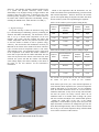
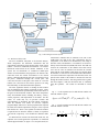
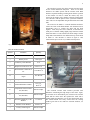
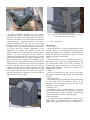
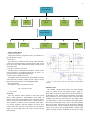
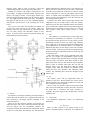
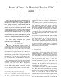
1 Breath of Fresh Air: Motorized Passive HVAC System W. Giaimo, M. Haldeman, C. Iseri, C. Le, K. Lorenzen, Abstract—The majority of energy use in residential homes goes toward the heating and cooling of the house. A very simple and efficient way to save money on an energy bill is by utilizing the natural air and heat flow between the inside and outside of the house. Opening and closing the windows and blinds allows the heat and air to flow easily. However, it is not always practical to manually open and close the windows and blinds to optimize flow. We designed and built an automated window and blind opening system that adapts to an existing window setup. The windows and blinds are opened and closed based on cues from temperature sensors and direct user input. The system fits onto an existing window so that the customer does not need to purchase an entirely new window system. This solution provides customers an easy way to save money on their energy bill by automating the opening and closing of the windows and blinds. Index Terms— Energy consumption, Temperature control, Thermal analysis A Green products, I. INTRODUCTION ccording to the Department of Energy, heating and cooling homes in the US makes up 56 percent of total energy use in homes [1]. Windows end up wasting 30 percent of that power by letting heat in or out [1]. Heat escapes the windows and allows cold air to enter in the winter, while in the summer the windows create a greenhouse effect that counteracts air conditioning. Even when the air is cool outside, if the sun is shining through the windows, the air inside can become much hotter than the air outside. Instead of using precious resources, like natural gas or coal, the sun or a breeze could be used to heat or cool these homes. Shades can also be opened to let light and heat in or closed to trap heat in or keep the sun out. Passive heating and cooling utilizes the solar power from the sun and movement of air from the wind, instead of using a central air system. But, unless a house is designed with passive cooling in mind, the homeowner is required to open and close all the windows manually. Unfortunately, with busy schedules, it is not always practical for the homeowner to open and close the windows and shades at the appropriate times to Manuscript received May 16, 2012. This work was supported in part by Puget Sound Energy under the Energy and Efficiency grant. Authors WG, MH, and CL are working with the EE department at Seattle Pacific University in Seattle, WA. Authors CI and KL are working with the ME department. This project was produced in senior design during the 20112012 school year. Advisors are Dr. Kevin Bolding and Prof. Christopher Lanning most effectively cool or heat the home. The priority for most homeowners is comfort and convenience, rather than energy savings. The challenge here is to provide a cost-effective way to passively heat and cool an already existing home. Because heating and cooling results in more than half of the energy used in homes, reducing the use of central air systems could make homes considerably more affordable [1]. Photovoltaic and solar thermal panels can end up being more expensive than the energy they save, especially in overcast locations [2]. A cost-effective, passive system could result in a better bottom line for the customer and be much more accessible to busy homeowners. A good solution would make passive heating and cooling more accessible by providing a system that could be retrofitted to an existing home andbe able to save a homeowner more money than it originally cost over a ten year period. This system would also be adaptable to different climates and weather conditions. Finally, the system would be reliable and customizable. Every home and homeowner is different; they have different designs and different priorities. A good product would be able to cater to many different tastes and layouts while still being as effective as possible. A. Existing Solutions The solutions to our problem all fall under the category of smart house technology. Smart houses are houses that use information technology to improve the comfort, convenience, security and efficiency of the house itself for the benefit of its inhabitants [3]. Once only a piece of science fiction, smart homes are becoming a reality. There are famous smart houses, like Bill Gates’ home, and there are many houses that incorporate smart technology in a more subtle fashion. Our focus on smart house technology is increasing the efficiency of the house. We will do this by using the information we gain from sensors to passively control the climate inside the house and therefore conserve energy. Although there are a number of products on the market similar to ours, none incorporate all of the features of our system. BTX makes a motorized shade system that is remote controlled, but it is expensive, complex to install, and doesn’t interface with control units [4]. The Add-A-Motor 45/80 Motorized Drape Controller, on the other hand, offers easy installation, interfacing with wall-mounted keypads, universal remotes, and computers. This type of product seems to work well for U shaped loop cords, but not other types of blinds and 2 drapes [5]. The Ultraflex Vega RF controlled window motor is a system that provides motorized, remote control functionality to any skylight, awning, or hopper window, and provides a cable for a rain sensor. It doesn’t have any other interfacing ability, though [6]. There are a number sensors on the market that combine temperature and humidity sensing, including the THUM sensor, which interfaces via USB [7]. II. DESIGN A. High Level Design: The system will help to reduce the amount of energy used by a central heating/air conditioning system by controlling the windows and shades automatically. The homeowner will be able to set up a desired inside temperature on the user interface. The system will then compare the indoor and outdoor temperatures with the user preference and then open or close the window or shades in order to optimize energy efficiency. The user interface will communicate wirelessly via Bluetooth to the sensors on the outside of the house. The three types of sensors used are temperature sensors, a rain sensor, and a humidity sensor. The temperature sensors will be used in the comparison of the indoor and outdoor conditions to know when to open and close the window and blinds. The rain sensor will be placed on the outside of the house and, when activated, the system will shut the window. The humidity sensor simply displays the relative humidity of the inside of the house on the user interface for the homeowner’s information. Based on the temperature that the homeowner sets, the window and shades will respond differently given the internal and external temperatures. Table IA shows how the window system will respond during the daytime and Table I-B shows how the window system will respond during the nighttime: Table I-A: The window system responses during the day Desired Effect Inside Heat Index (compared to outside) Window Response Shade Response Heat Warmer Close Open Cool Warmer Open Close Heat Cooler Open Open Cool Cooler Close Close Table I-B: The window system responses during the night Desired Effect Inside Heat Index (compared to outside) Window Response Shade Response Heat Warmer Close Close Cool Warmer Open Open* Heat Cooler Open Open* Cool Cooler Close Close The asterisks (*) represent that the user can choose whether the shades are open or closed for this condition. In the warmer part of the year, if the outside temperature is cooler than the inside temperature, the system will adjust the windows and blinds to cool the house. For air conditioner users, the window thermostat needs to be set lower than air conditioner thermostat, so they do not overlap. This will make sure that the system can always activate before the air conditioner turns on. If weather starts to change, the system will close windows and adjust to the suitable blinds position. During the colder parts of the year, if the outside temperature is warm and there is plenty of sun, the system will adjust the blinds to maximize the sunlight that goes into the house. When the light intensity starts to decrease (based on the time of day) or the outside temperature drops, insulated blind covers will be released to reduce heat lost. Fig. 1 - High Level Design in Solidworks. This figure shows the user interface, motor control board and the two motors. 3 Fig. 2 - Block Diagram of Entire System. B. Mechanical Subsystems The first mechanical subsystem is the thermal analysis, which incorporates the theoretical calculations and the experimental verification. Using the three basic forms of heat transfer—convection, conduction, and radiation—we created a theoretical model based on the window conditions of the system. For our calculations, we considered a double-pane window of known thickness and properties. We looked at the convection from the outside environment to the outside surface, conduction through the first pane, convection between the panes, conduction through the second pane, and convection from the second pane to the inside air. The heat transfer rate is the same in each of these processes. So using this relationship, we determined the final equations. The most significant obstacle to finding the heat transfer rate was finding the heat transfer coefficient (h-value). These values were determined experimentally based on the nature of the gases in and around the window. This value incorporates many environmental factors, including the density, velocity, viscous properties, and temperatures of the fluids. For this reason, we could only rely on previous research and experimentation to determine the heat transfer coefficient. After the estimates were found, we used the computer programs Maple and Excel to develop equations that required the inside and outside temperatures and gave us the expected heat transfer rate. There is one equation for when the window is open and one for when the window is closed, see equations 1-A and 1-B, respectively. The variables are defined in table II. To determine how accurate our theoretical model was, the equations were tested against the experiments we conducted with the physical model, see figure 3. To set up this model, we constructed a chamber that we attached to one side of the window that was used as the “hot” environment. The key components of the model were thermometers, heat lamps, a heat flux sensor, and insulators. For insulation, we used lowdensity oriented strand board (OSB) and cotton. The OSB was used for the construction of the chamber and cotton towels were used to create an insulated seal between the window frame and the wood chamber. Heat lamps were placed inside the chamber to create the hot environment and a thermometer was used to measure the temperature. The heat flux sensor was placed on the outside of the window to measure the heat flux through the window surfaces. This design allowed us to gather data and compare it with the theoretical data we calculated using the equations. The results are described in section IV. Eq. 1 – A: The equation used to find the heat transfer rate when the window is open. ( ) ( ) Eq. 1 – B: The equation used to find the heat transfer rate when the window is closed. ( ( ) ) 4 The interfaces between the motors and the electrical parts are the second mechanical subsystem. There are two main interfaces: the shades opener and the window crank. Both interfaces required attaching a rotating motor shaft to a portion of the window. In order to mount the motors, they were secured to the window sill or shades so that the rotating shaft was concentric with the portion of the system that needed to rotate. This was accomplished using metal brackets and small bolts. The motor for the shades is a smooth shaft that needed to connect to a hook of the shades handle. We decided to use an intermediate piece to connect the shaft and the hook together. After many ideas were evaluated, we decided on a small piece of flexible tubing slightly larger than the smooth shaft of the motor. It was secured to the motor using a circular clamp and a horizontal hole was drilled in the top for the hook to attach to. The interface is shown in figure 4. This connection has proved to be very reliable and inexpensive. Fig. 3 - The thermal model used to test the theoretical equation Table II: Defined variables Symbol Definition Quantity A Area of the window 0.723 m2 ρ Density of Air 1.247 kg/m3 ε Emissivity of the Window 0.93 Ce Empirical Coefficient of Air 0.9525 x 10⁻⁵ h1 Heat Transfer Coefficient of Air 4.075 W/m2 K h2 Heat Transfer Coefficient of Argon 14.6 W/m2 K cp Specific Heat of Air 1.0005 kJ/kg K σ Stefan-Boltzmann Constant 5.67 x 10⁻⁸ W/m2 K4 Te Temperature of the External Air (Absolute) Based on input Ti Temperature of the Internal Air (Absolute) Based on input k Thermal Conductivity of the Window 1.1 W/m K d Thickness of the Window 0.003175 m v Velocity of Moving Air Based on input Fig. 4 - The interface between the shades and the motor. The casement window crank interface provided some difficulties considering the high torque of the motor. Again, we decided on an intermediate part in between the window crank and the motor itself. We replaced the crank with a smaller handle and shaped it to fit on the slotted motor shaft. The smaller handle was easily secured onto the existing window given that it was made for casement windows, see figure 5. 5 Fig. 5 - The interface between the window crank and the motor. The third mechanical subsystem was the enclosures surrounding the electrical components and motors. The four enclosures—the window motor, shades motor, user interface, and motor control board—were created using the Solidworks CAD software (the . Though the process to create them is relatively straightforward, it took some time due to slight physical revisions. For the motors, enclosures were created to be slipped on from one direction and fit the outermost parts very closely; thus many accurate measurements of the components were required. The enclosures for the user interface and the motor control board were created in a similar fashion to the motor enclosures, but also required an additional part. This part allows the component to be mounted to the wall and holds the cover in place. In addition, since these components have temperature and humidity sensors attached, slots were needed in the enclosures that allowed for adequate air flow to the sensors. Each enclosure also required holes for wires and a power supply and the user interface required easy access to the LCD screen and buttons. One final component was the rain sensor holder, which attaches to the motor control board. The sensor was secured at an angle so that water could run off it. This part was screwed into the top of the enclosure to rest at an angle. Fig. 6 - The window motor enclosure Fig. 7 - The shades motor enclosure. Fig. 8 - The motor control board with the attached rain sensor (top) and the user interface enclosure (below) C. Electrical Subsystems User Interface 1. Microcontroller The microcontroller is the Cypress Programmable System on Chip 1 (PSoC1). It is programmed to control the LCD, monitor the buttons, receive temperature and humidity, and handle the Bluetooth communication between the user interface and the motor control board. 2. LCD The screen will be a 4 row, 20 character parallel LCD. It will be powered by a 5V DC power supply and connected to the microcontroller. Based on the user’s selections, the microcontroller sends commands to the LCD in order to display suitable instructions. The LCD also includes a green backlight for use at night. 3. Buttons There are five buttons for up, right, down, left, and enter. The buttons are used to navigate various menus and change variables. 4. Temperature Sensor The temperature sensors communicate with the PSoC using I2C. The PSoC reads the temperature register on the temperature sensor continuously and receives the outside temperature every ten seconds. 5. Humidity Sensor The humidity sensor is mounted directly to the circuit board. Humidity sensor collects and measures the conductivity of the air and outputs a voltage. The PSoC will measure this voltage continuously and scale it to the proper range. 6. Bluetooth Module The Bluetooth Module communicates with the PSoC through UART. It is powered off the 3.3 V switching power supply, which is separate from the rest of the board’s power. 6 Motor Control Microcontroller DC Motor Stepper Motor Temperature sensor Rain sensor Bluetooth module Humidity sensor Bluetooth module User Interface Microcontroller LCD Buttons Temperature sensor Fig. 9 - Block diagrams of the electrical subsystems Motor Control Board 1. Temperature Sensor This board also has a temperature sensor, see number 4 of the user interface section. 2. Rain Sensor The rain sensor is a basic two wire system. When rain falls, it lowers the resistance and this is measured by an ADC on the PSoC. The sensor will be mounted at an angle so that rain will run off the sensor. 3. DC Motor (Window Operation) The DC motor is connected to the window. The DC motor will be powered by a regulator connected to AC power. To turn on the motor, a simple H-Bridge is used. 4. Stepper Motor (Blinds Operation) The stepper motor connects directly to the blinds via a hook and replaces the rod that is usually present. Using a stepper motor allows more precision in controlling the blinds. 5. Bluetooth Module See number 6 of the user interface section. III. IMPLEMENTATION A. Key circuits UI circuit The User Interface board contains a Real Time Clock (RTC), which produces a programmable clock output. It displays the system’s clock and memorizes time setting from a user via a two-line bidirectional I2C Bus. A quartz crystal is used with RTC in order to create an electrical signal with a very precise frequency, and this frequency is used to keep track of time. RTC also has a coin battery for its memory. Figure 10 on the right shows the clock’s circuit with the battery added. Fig. 10 - RTC circuit with coin cell battery and adjustable capacitor Window circuit The window control board utilizes two dual H-bridge circuits to control the DC and stepper motors. Figure 11 shows paths of current in different drive and decay modes for the H-bridge circuits. Each of the four transistors in the bridge can be turned on or off to conduct current, so that the motor windings can be driven in either direction. The stepper motor is a bipolar motor, so it has two windings, which must each be driven with an H-bridge circuit. This is why dual H-bridge chips were chosen, so that one chip can drive all the windings on a stepper motor. The DC motor only requires one H-bridge circuit, so the chip is used in parallel mode. Parallel mode (shown in Figure 5) allows for double the current to a single 7 H-bridge circuit, which is ideal for driving a motor that requires a high amount of torque, like our DC motor does. Another key element of the window control board is the power supply. To supply an adequate amount of power to the motors, a 9V supply is needed. The 9V supply chosen was a black box supply that plugs directly into the wall and outputs 9V. This supply powers the motor driver chips. The output of this supply is then run into a 3.3V buck switching regulator that provides efficient power to the remaining ICs on the board. Two rows on screw down wire terminals were added: one for the motor wires, and one for the sensors. These wire terminals ensure that the connections are solid and that the user can easily connect and disconnect sensors as they choose. It ensures that the system will function reliably and that installation will not be difficult. Fig. 11 - H-bridge drive and decay modes outside temperature are displayed on the screen. When the up button is pressed on this screen, the unit enters menu mode. From this screen buttons can be pressed to enter the various menus: temperature set, time set and manual control of the motors. A variable called ‘currentMenu’ keeps track of what menu is accessed and continuously enters the main loop anc calls the appropriate function. Conversely, the motor control board simply measures the temperature every ten seconds, sends it to the user interface and then waits for any other commands from the user interface board. A Bluetooth command from the other board triggers an interrupt and acts according to the hex value sent – the hex value signifies which motors should activate in which direction. C. Cost Cost reduction is an important part of this design since the end goal is marketability to consumers. For this reason, the integrated circuits chosen were not only chosen for their functionality, but also for their cost. Many chips inherently have a high cost, so the cheapest options that maintained the desired functionality were the ones chosen. For example, the Bluetooth chip chosen for the design is used with a breakout board for testing. If the board goes into mass production this breakout board can be eliminated, and the cost of the chip will be reduced by 50%. Other chips reduce overall cost by combining many tasks into one. For example, the programmable system on chip (PSoC) combines many functions such as an analog-to-digital converter (ADC), I2C master, and control module for other chips on the board. The ease with which the chip is adaptable makes it ideal to combine many tasks into one unit and therefore reduce costs. The motor driver chips are another example of this. Each chip contains two H-bridge circuits which each have four transistors and additional control circuitry. By combining these circuits the integrated circuit reduces costs. D. Size Fig. 12 - Parallel Mode B. Software The software in our design will mainly provide the ability to receive data from the sensors array, compare the data with the user’s preferences, and trigger suitable commands to the window mechanism. There are two main software structures in our design: UI and motor control. The UI has a main loop that waits for input from the buttons and also continuously measures the temperature, humidity and communicates with the RTC. When the unit is in ready mode, the humidity, time and inside and The window system will not significantly affect the aesthetics of the room. When installed, the sensors will be placed strategically as to not ruin the aesthetics of a room, and also to keep out of reach of children. The size of the user interface will be no larger than a high end, touch screen thermostat. It will be placed in a location in the house that is convenient and easily accessible to occupants. The power supply for this module will be located behind the wall. E. Construction See Mechanical Subsystems section for construction information. IV. RESULTS There are three portions to the results section of the project—the thermal analysis verification, the completion of 8 our test plan, and comparing the window system power consumption to a typical HVAC power consumption. The purpose of these tests was to confirm that our project fulfilled all of the aspects on the specification document. To test the theoretical thermal model (for background, see part B of section II) we compared the equations we developed with the physical model we created. The heat flux sensor used to measure the heat flux from the physical model gave us some minor problems originally. We needed a microvolt meter to measure the very small voltages, but we only had a millivolt meter. We could not get an accurate enough voltage to determine the heat flux. In order to mitigate for this problem, we created a circuit that amplified the voltage one thousand times to be able to read the voltages accurately. Once we fixed this, these consistent voltages were then calibrated to the sensor and we were able to find the heat flux through the window. We compared this value to the theoretical equations and found that the two models differed by a maximum of nine percent and a minimum of three percent. We were hoping that the models would differ by less than ten percent, so we were very pleased that they showed so much agreement. In confirming the success of our project, we tested our project rigorously. There were three main parts to our test plan: verifying the proper operation of the individual parts of our project, verifying to operation of the project as a whole and verifying that our project is easy to use. The individual aspect tests represented a wide range that made sure all the parts of our project worked as expected. Simple tests included rain sensor operation, button endurance, consistent automatic pairing of the Bluetooth modules, DC & stepper motor operation and the LCD backlight test. All of the simple tests made sure that the individual parts of the project worked on their own. All of the tests in this section passed without any modifications. The operation tests made sure that the project as a whole worked. The test also confirmed that the system reacted as expected (in concordance with Table 1-A and Table 1-B). First, we tested the blinds and window response to temperature change separately and then together. When each motor was tested separately, they worked well, but the first time the motors were tested together, the window would occasionally not open all the way. By modifying the software so that the stepper motor (which is activated first) has a wait routine after it is used, the problem was mitigated. Finally, the user tests established that our unit was easy to use with the instruction manual. We completed one test that timed how long it took for an average, computer literate user to program our unit, and another test taking input on the user document itself. Both of these tests passed on the first test pass without any changes to the user manual. Another area of testing that we completed was comparing a typical HVAC unit’s power consumption and our system’s power consumption. A typical HVAC system can use up to .45 and .56 kW, whereas our system used less than a hundredth of a kW. Although this means that the test passed, our system cannot be as effective as a traditional heating and cooling system. Our system can only normalize the temperature between the inside and outside temperature, which would assist a traditional HVAC system and minimize the user’s reliance on it. V. FUTURE WORK AND IMPROVEMENTS The goal of this project was to create a system that could open and close a home’s windows in order to reduce the use of a typical HVAC system. This system has fulfilled this goal, but only, so far, for a casement (crank) window and a typical Venetian blind. In the future, the system would hopefully incorporate these elements: universality, better user interface elements, photodiodes and power saving software modifications. The universality of the system was not in the scope of our senior design project. Fresh Air focused on one type of window and one type of blind. However, in the future the Fresh Air Motorized Passive HVAC System, would work for any window and with any type of blind. It would also work for skylights and any other inaccessible windows in office buildings, schools or other commercial buildings. The system in the future would also be able to raise and lower venetian blinds, as well as accordion blinds or honeycomb blinds. Although our user interface is sophisticated enough for the time being, a more sophisticated model would be more beneficial and appealing for the user. In this prototype, Fresh Air focused on functionality rather than aesthetic. The buttons and 4x20 LCD do work, but a touch screen would be more appealing for future versions of the product. Also, a ‘sleeker’ look to both the user interface module and the motor module would make this product more popular in the market. The Fresh Air passive HVAC system includes many sensors, but for simplicity, we did not include a photo sensor. A photo sensor for each window would improve the effectiveness of the passive heating and cooling. When the sun is out, but it is cooler outside than inside, and the house should be cooled, then the blinds should be shut and the window should be open. A photo sensor would provide more feedback so that the sensor can make better decisions about how it should react to the temperature changes in the environment, both inside and outside. Finally, because the main goal of the system was to save power, a better version of software should be written to reduce the power consumption of the system as a whole. The PSoC has a sleep function that could be easily implemented in the future for the UI to turn off the screen and backlight automatically after a period of inactivity. The sleep feature could also be used for the motor board which would only have to wake up to receive a command from the user interface or retrieve the temperature reading from the temperature sensor. Also, the motor board could use a battery and a solar panel, instead of electricity, to power the motors that open and close the windows, further saving electricity. VI. CONCLUSION The system is just what we have hoped for this preliminary prototype. We have fulfilled all of our major goals: 9 automation, wireless connection, customizability, and expandability. The wireless connection is stable and consistent and the system as a whole works well. Not only is this system a novel idea, but it is also a sustainable one. By helping homeowners save energy, Fresh Air hopes to help save the planet. VII. REFERENCES [1] [2] [3] [4] [5] [6] [7] Energy.gov | Department of Energy. US Department of Energy. Web. 16 Oct. 2011. <http://www.energy.gov>. US Department of Energy, "Energy Efficiency and Renewable Energy," 9 February 2011. [Online]. Available: http://www.energysavers.gov/your_home/space_heating_cooling/index.c fm/mytopic=12650. [Accessed 10 May 2012]. R. Harper, Inside the Smart Home, R. Harper, Ed., London, Springer, 2003. "BTX Motor Controlled Roller Shade System with 3 Percent Openness Charcoal/Bronze (36 X 108 In) - Smarthome." Smarthome - Home Automation, X10, Remote Control, Lighting, Wireless Security. Web. 16 Oct. 2011. <http://www.smarthome.com/31468CC/BTX-MotorControlled-Roller-Shade-System-with-3-Percent-Openness-CharcoalBronze-36-x-108-In/p.aspx>. "Add-A-Motor 45/80 Motorized Drape Controller - Smarthome." Smarthome - Home Automation, X10, Remote Control, Lighting, Wireless Security. Web. 16 Oct. 2011. <http://www.smarthome.com/3142/Add-A-Motor-45-80-MotorizedDrape-Controller/p.aspx>. "Vega RF Window Motor System - AC - Rain Sensor Ready." Home Automation Products and Support from the Leader in Home Automation, HomeControls.com. Web. 16 Oct. 2011. <http://www.homecontrols.com/Vega-RF-Window-Motor-System-ACRain-Sensor?sc=23>. "THUM - USB Temperature/Humidity Sensor - Smarthome." Smarthome - Home Automation, X10, Remote Control, Lighting, Wireless Security. Web. 16 Oct. 2011. <http://www.smarthome.com/15250/THUM-USB-TemperatureHumidity-Sensor/p.aspx>.