1
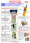
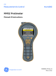
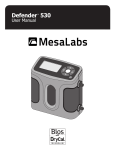
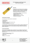
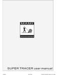
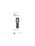
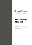
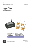
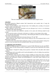
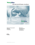
®
Moisture Measurement System
Instruction Manual
Protimeter MMS, Protimeter MMS Plus
CONTENTS
Introduction
1
1.0 Product Familiarisation
1
1.1 Switching the MMS On and Off
3
1.2 Optional Accessories
3
2.0 Moisture Meter Modes
4
2.1 Search Mode
4
2.2.0 Measure Mode
5
2.2.1 Using Auxiliary Moisture Probes in Measure Mode
5
2.2.2 Detecting hygroscopic salts
6
3. Hygrometer Mode
6
4. Condensator Mode
7
5. Setup Mode
8
6. Hold and Logging Mode
9
7. Diagnostic Procedure Guidelines
10
8. Calibration Checking
12
9. Care and Maintenance
12
10. Technical Specification
13
Appendix 1: Guidance notes for measuring in floors
14
Appendix 2: MMS Plus (BLD5800 LH) Additional functions
16
Introduction
The Protimeter Moisture Measurement System (MMS), is a powerful and versatile
instrument for measuring and diagnosing dampness in buildings and building
materials. This product enables building surveyors and other practitioners to measure
moisture levels of building elements such as walls, floors and building environments
simply by switching between the three different modes of operation. In this way, a
detailed understanding of the moisture condition of the property can be obtained.
1.0 Product Familiarisation
The Protimeter MMS kit comprises a carry case containing the MMS instrument and a
range of standard accessories, as detailed in table 1.
Description
Protimeter MMS / MMS Plus
Comprising:
Protimeter MMS instrument
Hygrostick hygrometer probe
Hygrostick extension lead
Moisture probe
Deep wall probes (length 140mm)
Surface temperature sensor (direct contact)
Carry case
Calibration check device (for %WME)
Instruction manual
Part Number
BLD5800 / BLD5800LH
POL5800 / POL5800LH
POL4750
BLD5802
BLD5060
BLD5018
BLD5804
POU5800-01
BLD5086
INS5800
Table 1
POU5800-01
POL5800
BLD5802
BLD5804
BLD5018
POL4750
BLD5060
1
The MMS instrument is a battery powered handheld unit that has cluster of four buttons
and a large liquid crystal display (LCD). The bulge at the top of the instrument houses
a sensor for detecting moisture within solid materials. Edge connection1 (EC1) is for
use with a Hygrostick probe. The jack-socket (JC) is for use with a moisture probe, deep
wall probes or hammer electrode. EC2 is for use with the Direct Contact Surface
Temperature Sensor and for connection to a PC when using the optional MMS logging
software.
EC 1
EC 2
Search Mode
Sensor
JC
The Hygrostick probe measures relative humidity (%rh) and ambient air temperature
(TAIR) in rooms or materials. It can be connected directly to the MMS instrument or by
means of the Hygrostick extension lead. The surface temperature sensor is used (TS)
when investigating condensation situations. The moisture probe is used to obtain
percent moisture content values in wood or wood moisture equivalent (WME) values in
other non-conductive materials. Deep wall probes are used to obtain WME values at
depth in solid structures such as walls and floors.
2
1.1 Switching the MMS On and Off
Prior to initial use, ensure that two LR6 batteries are correctly inserted in the battery
compartment. Note that low battery power is indicated by ! on the display; when this
appears, replace the batteries. Switch the MMS on by pressing
momentarily. The
MMS will switch off automatically after 1 minute unless the default setup is changed
(see section 5). Alternatively, switch off by pressing
and holding for 3 seconds or
more. Once
has been depressed for 3 seconds all text information blocks appear
on the display; these disappear when
is released and the unit switches off.
1.2 Optional Accessories
A range of optional accessories may be used with the Protimeter MMS and MMS Plus.
These include Hammer Electrodes, memory access software and deep wall probes. For
more information please contact GE Protimeter or your official Protimeter supplier.
3
2.0 Moisture Meter Modes
The MMS can be used to detect and measure moisture in non-conductive solid
materials such as wood and masonry. Two modes of operation are available, the
Search mode for qualitative measurements and the Measure mode for precise and
localised moisture content measurements in wood or WME values in materials other
than wood.
2.1 Search Mode - Selection and Use
Turn the MMS on by pressing
. Select the moisture meter mode by pressing
zzzzzsuccessively until the word MOISTURE is visible in the top right corner of the LCD.
Then press
to select the Search mode, indicated by REL•)))) on the LCD.
The instrument can now be used to take relative moisture readings in solid,
homogenous materials (such as walls and floors) by holding the leading edge of the
sensor bulge against the surface as illustrated, at an angle ranging from 20-50O.
Relative readings ranging from 0-1000 are given on the LCD together with a progress
bar that indicates if the material is in a DRY, AT RISK or WET condition.
As reliable readings will only be obtained if the leading edge of the sensor bulge is in
direct contact with the surface, the Search mode is not suitable for surveying textured
finishes. The nominal depth of penetration is up to 10mm in dense, homogenous
materials. Readings taken through lowdensity coverings (carpets, polystyrene
tiles etc) will not be representative of the
moisture level in the substrate itself. When
using the MMS in Search mode, it is
recommended that no attachments (i.e.
Hygrostick probe, Surface Temperature
Sensor or Moisture probe) are connected.
This practice will minimise reading errors
and the potential for electromagnetic
interference with other electronic
equipment.
4
2.2.0 Measure Mode Selection and Use
Turn the MMS on by pressing
. Select the
moisture
meter
mode
by
pressing
(((((((successively until the word MOISTURE is
visible in the top right corner of the LCD. Then
press
to select the Measure mode, indicated
by %WME on the LCD. Connect the Moisture
Probe (or other electrodes such as Deep Wall
Probes or Hammer Electrode - see section
2.2.1) to the MMS Instrument using socket (JC).
The instrument can now be used to take actual
%MC readings in wood and %WME readings
in non-conductive solid materials other than
wood by pushing the Moisture Probe pins into
the surface. The measured value is displayed and the progress bar indicates whether
the material is in a DRY, AT RISK or WET condition, as summarised in table 2.2.
%MC (wood only) or %WME value Instrument display in MOISTURE Measure Mode
< 8%
- - - % (denotes out of range), inactive progress bar
≥ 8% but < 17%
%MC or %WME value, DRY, active progress bar
≥ 17% but < 20%
%MC or %WME value, AT RISK, active progress bar
≥ 20% but < 28%
%MC or %WME value, WET, active progress bar
≥ 28 to 100
Relative value only, active progress bar
Table 2.2
2.2.1 Using Auxiliary Moisture
Probes in Measure Mode
When sub-surface readings are required in masonry, the
Deep Wall Probes should be used instead of the standard
Moisture Probe. To use, drill two ø 6mm clearance holes
50 - 75mm apart to the required depth. Push the two Wall
Probes into the holes and press and hold the tips firmly
against the bottom of the holes. Ensure that the probes are
connected to socket (JC) and measure the %WME value as
described in section 2.2. The most convenient way to take
sub-surface readings in wood is by using an optional
Hammer Electrode.
5
2.2.2 Detecting Hygroscopic Salts
The MMS instrument can be used as a basic salts detector when used with the Moisture
Probe, filter papers and distilled water (not included). Moisten the filter paper with the
water and take a reference reading across it with the Moisture Probe. Then place the
moistened filter paper against the surface of interest and hold in place for 30 seconds.
Remove the paper and place the pins of the Moisture Probe across the paper again
and observe the reading and compare with the original reference reading. If the
difference is more than 20 points there is significant salts contamination that may
warrant further investigation.
3. Hygrometer Mode - Selection and Use
To use the MMS as a hygrometer, connect the Hygrostick probe directly into (EC1) or
indirectly, by means of the Hygrostick extension lead. Turn the MMS on by pressing .
Select the hygrometer mode by pressing
successively until the word HYGROMETER
is visible in the top left corner of the LCD. Then press
to select relative humidity
(%rh), ambient temperature (TAIR) or dew point temperature (TDEW) as required.
Temperature values can be displayed in OC or OF (see section 5 for setup).
%rh and TAIR measurements are made by the
Hygrostick sensor and the MMS instrument
uses these values to calculate TDEW. When
using the MMS to measure the conditions in
air, the Hygrostick probe is normally
connected directly to the instrument. When it
is impractical or awkward to use the
instrument in this way, the Hygrostick
extension lead may be used to connect the
Hygrostick to the instrument. Typically, the
extension lead will be used when taking
readings from Hygrostick probes that have
been embedded in structures such as walls
and floors.
6
4. Condensator Mode
The Condensator mode enables the user to
assess the risk of condensation occurring
on surfaces or to confirm whether or not
condensation is present on a surface.
To use the MMS as a Condensator,
connect the Hygrostick probe directly into
EC1 and connect the Surface Temperature
Sensor (either the standard direct-contact
type or the optional infrared remote type)
into EC2. Turn the MMS on by pressing
button
. Select the Condensator mode
by pressing
successively until the word CONDENSATOR is visible in the top
centre of the LCD. Then press
to select relative humidity (%rh), ambient temperature
AIR
DEW
(T ) , dew point temperature (T ), surface temperature (TS) or temperature difference
(TDIFF) as required. TS and TDIFF measurements can only be obtained if a Surface
Temperature Sensor is connected to the instrument and held against the surface of
interest. Temperature values can be displayed in OC or OF (see section 5 for setup).
TDIFF is a useful function when investigating condensation as it tells the user how many
degrees a surface is above or below the prevailing dew point temperature. When a
surface is more than 3 OC above dew point, TDIFF is displayed with the message NO
CONDENSATION. When the surface temperature is 3 OC or less above dew point, TDIFF
is displayed with the message AT RISK, NO CONDENSATION. When the surface
temperature is equal to or lower than the dew point, a negative TDIFF is displayed with
the message CONDENSATION. The progress bar is activated when TDIFF is less than
14OC above dew point. It moves from left to right to signify the increasing risk of and
degree of condensation. Table 4. summarises this functionality.
Temperature of Surface
> 14OC above dew point
≤ 14OC but > 3OC above
dew point
≤ 3OC above dew point
≤ dew point
Instrument display in CONDENSATOR TDIFF Mode
TDIFF, NO CONDENSATION, inactive progress bar
TDIFF, NO CONDENSATION, active progress bar
TDIFF, AT RISK, NO CONDENSATION, active progress bar
TDIFF, CONDENSATION, active progress bar
Table 4.
7
5. Setup Mode
The Protimeter MMS instrument has a range of features that can be selected by the user
as listed in table 5.
Setup
Code
S1
S2
S3
S4
S5
S6
DEF
0.00
T1
Table 5.
Setup selection
Displays temperature values in OC
Displays temperature values in OF
Activates LCD back light
Deactivates LCD back light
Activates bleeper
Deactivates bleeper
Default settings (OC, activated back light, activated bleeper, 1 minute auto switch off)
Real-time clock (adjustable only through IrdA comm port with Protimeter software)
Auto switch off adjustment, from 1minute to 6 minutes
To enter the Setup mode switch the instrument on and disconnect any attachments that
may be connected. When the display shows three horizontal dashes ( - - - ), press.......
momentarily; the word SETUP then appears in the bottom left hand corner of the LCD
together with the code S1 in the centre of the display. Within three seconds,
press
successively to scroll through the setup codes as detailed in table 5. Press
to
set the selected setup option.
Example 1 - deactivate back light and change temperature readings from OC to OF
• Enter Setup mode by pressing button
momentarily when display shows - - • Scroll to S 4 by pressing
• Press button
to select the deactivated backlight option
• Scroll to S 2 by pressing
• Press
to select the OF display option
• Press
momentarily to return to operating modes, or leave for three seconds
The instrument would now display temperatures in OF without any backlighting.
Example 2 - change the default auto switch off from 1 minute to 5 minutes
* Enter Setup mode by pressing
momentarily when display shows - - * Scroll to t 1 by pressing
* Press
four times in succession; display now shows t 5
* Press
momentarily to return to operating modes, or leave for three seconds
The instrument would now switch off automatically after five minutes.
8
6. Holding and Logging Mode
Moisture, temperature and RH values can be held by pressing and holding
. If the
button is held down for less than three seconds, the instrument reverts to the mode of
measurement that had been selected previously. If held down for more than three
seconds, the instrument switches off when
is released (see section 1.1).
Readings can be logged in the MMS memory (minimum of 300 line entries) by
pressing
. Table 6 details what information is logged when using this facility in the
operational modes. Contents of the memory can be downloaded to a PC running
Microsoft® Windows 95 or later, and loaded with Protimeter MMS Logging Software. For
further information please refer to the MMS LOGGING HELP DOCUMENT (INS5800L)
supplied with the Protimeter Logging Software CD.
Mode
Display
Information stored by pressing button
MOISTURE meter
REL•))))
yr/mm/dd, hr:min, relative value
example: 00/01/07, 09:30, 530
MOISTURE meter
%WME
yr/mm/dd, hr:min, %WME value
example: 00/01/07, 09:30, 12.5
HYGROMETER
%rh
yr/mm/dd, hr:min, %rh, TAIR, Hygrostick serial no.
example: 00/01/07, 09:30, 52.5, 21.2, 123456
HYGROMETER
TAIR
yr/mm/dd, hr:min, TAIR, Hygrostick serial no.
example: 00/01/07, 09:30, 21.2, 123456
HYGROMETER
TDEW
yr/mm/dd, hr:min, TAIR, TDEW, Hygrostick serial no.
example: 00/01/07, 09:30, 21.2, 10.5, 123456
CONDENSATOR
%rh
yr/mm/dd, hr:min, %rh, TAIR, Hygrostick serial no.
example: 00/01/07, 09:30, 52.5, 21.2, 123456
CONDENSATOR
TAIR
yr/mm/dd, hr:min, TAIR, Hygrostick serial no.
example: 00/01/07, 09:30, 21.2, 123456
CONDENSATOR
TDEW
yr/mm/dd, hr:min, TAIR, TDEW, Hygrostick serial no.
example: 00/01/07, 09:30, 21.2, 10.5, 123456
CONDENSATOR
TS
yr/mm/dd, hr:min, TS
example: 00/01/07, 09:30, 18.6
CONDENSATOR
TDIFF
yr/mm/dd, hr:min, TDIFF, TAIR, TDEW, Hygrostick serial no.
example: 00/01/07, 09:30, 8.1, 21.2, 10.5, 123456
Table 6.
9
7.0 Diagnostic Procedure Guidelines
When diagnosing dampness in buildings there are three key criteria that must be
considered as outlined in table 7.
Item Criteria
1
Is a wall or other building
element in a safe air-dry
condition?
Notes
2
Is the surface temperature
of a wall or other building
element above or below
dew point?
Dew point is the temperature at which a given
quantity of air becomes saturated (100 %RH)
and forms dew, or condensation. If a surface
is colder than dew point, condensation occurs.
When the Protimeter MMS Condensator mode
is selected to measure TDIFF (the proximity of a
surface to dew point) the instrument identifies
if there is NO CONDENSATION, an AT RISK
condition, or CONDENSATION occurring.
3
Is a wall surface or other
building element
contaminated with
hygroscopic salts or other
conductive materials?
Artificially high moisture meter readings may
be obtained in material that (i) has been
heavily contaminated by hygroscopic salts or
(ii) in materials that are conductive by nature.
The presence (or otherwise) of nitrates and
chlorides should be established when
investigating suspected rising dampness
situations in particular.
Air-dry is the moisture content that is normal
and safe (from moisture-related deterioration
or decay) in buildings. When the Protimeter
MMS moisture meter modes are selected,
measured values are identified as DRY, AT
RISK or WET.
Table 7
Item 1: The Search and Measure modes should be used in conjunction to (i) map out
the extent of a moisture problem and (ii) to distinguish between surface and subsurface moisture. The profile of readings obtained will give insight into the potential
cause (e.g. condensation, lateral ingress or rising dampness) of a moisture-related
problem.
10
Far greater insight will be obtained from moisture readings taken in a methodical
manner to those taken in a random manner. When testing walls, the user is
recommended to commence by taking readings at the skirting board level and move
up the wall in regular steps of 10-15 cm. When high sub-surface relative readings are
obtained in the Search mode, the user is strongly recommended to quantify these
values in %WME terms by using the Deep Wall Probes in the Measure mode. If the
depth of clearance holes is increased incrementally by a nominal 1cm at a time, the
moisture profile through the wall can be established.
Item 2: Condensation related moisture problems are arguably the most prevalent.
When assessing the risk of condensation, or confirming its existence, the proximity of
the actual temperature of the surface under investigation to the dew point must be
established. The TDIFF measurement in CONDENSATOR mode tells the user how many
degrees the temperature of a surface is above or below the dew point.
As many condensation situations are transient, TDIFF readings should be taken in a
methodical and regular manner, similar to moisture meter readings in materials.
Ambient RH and temperature values should also be taken to assess the moisture
condition of the room as a whole. Dwellings and working environments generally have
an RH of between 40% to 60%, so there may be cause to investigate environments that
register RH values outside this range.
Item 3: Two hygroscopic salts, chlorides and nitrates, may build up on the surface of
walls where rising dampness occurs. As groundwater moves through the wall and
migrates to the surface, salts tend to accumulate where the rate of evaporation of this
water is greatest. The salts themselves are non-conductive, but when mixed with a small
amount of moisture a highly conductive solution is formed. The presence (or absence)
of such salts should therefore be established when rising dampness is suspected by
using the Protimeter MMS in Measure mode as described. When required, the
Protimeter Salts Analysis Kit (part number BLD4900) can be used to identify the relative
concentrations of nitrates and chlorides.
In summary, effective dampness diagnosis is a process that draws on the knowledge
and expertise of the surveyor. The Protimeter MMS kit enables the practitioner to
investigate moisture levels in materials and environments from various perspectives
that, in turn, enables him/her to make more thorough and reliable judgements as to
the cause of dampness related problems.
11
8.0 Calibration Checking
Check the Moisture meter Measure mode by holding the pins of the Moisture Probe
across the exposed wires of the calibration check device (Calcheck). The WME value
of correctly calibrated instruments is between 17 - 19. Instruments that register values
outside this range should be returned to Protimeter (or an official Protimeter distributor)
for servicing. There is no facility to check the calibration of the Search mode.
Working Hygrostick probes can be checked against reference Hygrostick probes, or
against known humidities. Protimeter plc recommend those Hygrostick probes that
have drifted by more than ±5 %RH are discarded and replaced. New Hygrostick
probes are available from Protimeter plc or official Protimeter distributors.
9. Care and Maintenance
The Protimeter MMS is a precision built piece of electronic equipment that will provide
many years of reliable service if the following points are observed:
i. When not in use, keep the MMS instrument in its pouch together with its accessories.
Store the kit in a stable, dust-free environment and out of direct sunlight.
ii. Remove the batteries from the instrument if it is to be stored for periods of more than
four weeks, or when the low battery power symbol appears on the display.
iii.When using the MMS in Search mode, do not slide the bulge across surfaces as this
may lead to rapid instrument case wear. The instrument should be lifted and placed
in position to prevent erosion of the instrument case.
iv. Check the condition of accessories used with the MMS instrument on a regular basis
and replace them if they become worn or damaged.
v. To preserve calibration characteristics, Hygrostick probes should not be exposed to
saturated environments. If this is unavoidable, Hygrostick probes should be replaced
on a regular basis and their calibration should be checked at frequent intervals.
12
10. Technical Specification
Dimensions & Weights
Protimeter MMS Kit (BLD5800): 230 x 190 x 90mm, 1.2kg
Protimeter MMS instrument (POL5800): 180 x 70 x 45mm (max. values), 300g
Hygrostick probe (POL4750): length 50mm, ø 8mm. Optimal clearance hole ø 12mm
(when used with compression sleeve to measure ERH in solid material)
Power: x2 LR6 batteries
Measurement Ranges
Moisture Meter Search mode:
Moisture Meter Measure mode:
Hygrostick probe:
Measurement range:
0- 1000 relative scale, nominal depth of
measurement -15mm
tolerance ± 10 relative scale
8 - 29 %WME, 30- 100 relative scale in
saturated material
30 - 100 %rh, -10 to 50 OC
Tolerance:
30 - 40 %rh, ± 2.5 %rh @ 20 OC
40 - 98 %rh, ± 2 %rh @ 20 OC
-10 to 50 OC, ± 0.3 OC
Surface temperature sensor:
-10 to 50 OC, ± 0.3 OC
By pressing
while switching on using
displayed on the screen in sequence:
the following information is
Information
Example
Firmware version
Instrument part no.
%rh Calibration curve
Firmware date
Hygrostick serial no (when connected)
2.02
BLD5800
d2-5
yy-mm-dd
123456
13
APPENDIX 1
Guidance Notes for Measuring Moisture in Floors using
the Protimeter MMS
1 Rapid Moisture Level Assessment of Solid Floors
Primary Reference: Section 2.1 of MMS Instruction Manual
In Search Mode, the MMS can be used to assess the moisture level of solid floor slabs
in relative terms and to identify areas of concern that may warrant a more detailed
investigation.
Having selected the Search Mode (as detailed in section 2.1 of the MMS instruction
manual) hold the bulge of the instrument against the floor slab and note the value on
the LCD. Slabs that register a value of 200 or less are generally considered to be in a
safe air-dry condition. If values of more than 200 are recorded, we recommend that
the actual moisture level of the slab is quantified by alternative test procedures prior to
laying decorative floor coverings.
2 Equilibrium Relative Humidity Measurements in Solid Floors
Primary Reference: Section 3 of MMS Instruction Manual
In Hygrometer Mode, the MMS can be used to measure the equilibrium relative
humidity (ERH) value of solid floor slabs. In essence, this procedure measures the
relative humidity (%rh) of a pocket of air that is deemed to be in moisture equilibrium
with the material under investigation. Slabs that have an ERH value of 75% or lower
are considered to be in a safe air-dry condition. Slabs that have an ERH value of 80%
or greater are generally considered being in a damp condition.
Caution: moisture sensitive coverings that are laid onto damp floors may fail in service.
2.1 Sub-surface ERH Test Procedure - without using Protimeter
Humidity Sleeves
i. Drill 12mm (0.5”) diameter clearance holes to a nominal depth of 50mm (2”) at the
required points of measurement (POMs) and plug or cover with suitable
impervious material. Ideally, holes should be drilled 24-hours before
measurements are to be taken
ii. Remove the Hygrostick sensor and conical plastic sleeve
from the MMS pouch; push the Hygrostick through the
sleeve so that the tip of the Hygrostick protrudes fully
from the narrow end of the sleeve as shown.
14
iii. Push the Hygrostick-Sleeve assembly into the predrilled hole and twist firmly to seal as shown. Ideally,
leave the Hygrostick in the hole for 60 minutes before
taking a reading
iv. Use the extension lead (supplied in the MMS pouch)
to connect the Hygrostick to the MMS instrument (having
previously removed the protective yellow Hygrostick cap,
if fitted)
v. Select the Hygrometer Mode of operation (as detailed
in section 3 of the MMS instruction manual)
vi. Measure the %rh in the hole; this is the ERH value of
the floor slab
2.2 Sub-surface ERH Test Procedure - using Protimeter Humidity
Sleeves
Protimeter Humidity Sleeves are convenient optional accessories for use with Protimeter
Hygrosticks. Clearance holes are drilled at the required POMs and the Humidity
Sleeves are inserted. As each Humidity Sleeve has its own sealing cap, it is not
necessary to plug or cover the drilled holes. Having placed the Humidity Sleeves in the
floor slab (ideally, 24-hours before ERH measurements are to be taken) remove the cap
and follow the procedure as given above from 2.1 ii.
2.3 Surface ERH Test Procedure - using Surface Humidity Box
If it is impractical or undesirable to take sub-surface ERH readings (the best technique
for determining the actual moisture condition of the slab) the Hygrostick can be used
in combination with a Humidity Box placed on the surface. Typically, Humidity Boxes
are used on floors with embedded heating pipe work, or when a contractor is working
to standards that specify surface ERH techniques (e.g. BS 8203:1996).
A Protimeter Humidity Box (Part No. BLD4711) is available as an optional accessory.
It should be used in accordance with applicable standard recommendations, or placed
at the POM for at least 24-hours prior to taking ERH readings.
15
APPENDIX 2
BLD5800LH MMS ‘Plus’ - Additional Functions
The Protimeter MMS ‘Plus’ is a derivative of the standard Protimeter MMS that has
additional functionality as follows:
•
•
In Hygrometer mode, it can display the Mixing Ratio (Specific Humidity) of
moisture vapour in either grains/lb or g/kg of dry air
It can be used with an optional low humidity range sensor, Protimeter Part
No. BLD5812
Instructions to Display Mixing Ratio or Specific Humidity
The Mixing Ratio, or Specific Humidity as it is also known, is the mass of water vapour
per unit mass of dry air. This figure can be displayed in the Hygrometer mode of
operation, as detailed in section 3.
By Pressing
repeatedly in Hygrometer mode, the following measurements are
displayed in succession:
%rh
TAIR
TDEW
g.Lb
AbS
relative humidity
air temperature in either OC or OF
dewpoint in either OC or OF
Specific Humidity expressed as grains/lb (when the MMS is set up to measure
temperature in OF)
– or –
Mixing ratio expressed as g.kg (when the MMS is set up to measure temperature in OC)
The Mixing Ratio (AbS) or Specific Humidity (g.Lb) displays are accompanied by a momentary
beep to draw attention to the unit of measurement before displaying the value itself.
To change from OC to OF temperature measurement and vice versa, please refer to section 5.
BLD5800LH Logging Software
If required, measured values can be stored in the MMS ‘Plus’ memory for downloading to a PC.
Please refer to Section 6 for details. Only software version 2.04 and above, should be used
with the MMS ‘Plus’.
16
Instructions on using the Low Humidity Range Probe, BLD5812
The optional Low Humidity Range (LHR) probe measures humidity in the nominal range 040%rh.
It can only be used with the Protimeter MMS ‘Plus’ instrument as follows:
1.
2.
3.
4.
Select Hygrometer mode of operation as detailed in Section 3
Ensure that the Hygrostick is not plugged into the connection on the top of the instrument
Plug the LHR probe to the connection on the right-hand side of the MMS
Press to display %rh, temperature, dewpoint, Mixing Ratio or Specific Humidity as
required
Caution
Be aware that the relative humidity of many environments exceeds 40%rh. When the LHR probe
is connected in environments that exceed 40%rh the MMS instrument diplays o - r, denoting out
of range.
The LHR probe must not be plugged into the socket on the top of the MMS instrument. Be aware
that this could damage the instrument.
BLD5812 Low Humidity Range Probe Specifications
Nominal measurement range:
0 - 40%rh
Uncertainty ± 2.0%rh @ 20 OC
0 - 40 OC
Uncertainty ± 0.3 OC
The information contained in this manual is given in good faith. As the method of use
of the instrument (and its accessories) and the interpretation of the readings are beyond
the control of the manufacturers, they cannot accept responsibility for any loss,
consequential or otherwise, resulting from its use.
Protimeter® and Hygrostick® are registered Trade Marks of Protimeter plc
GE PROTIMETER plc
Meter House, Marlow, Bucks SL7 1LW. England
Tel.: +44 (0) 1628 472722 Fax: +44 (0) 1628 474312
E-mail: [email protected]
Web Site: www.protimeter.com
GE Protimeter North America: Tel: +1 800 321 4878
GE Protimeter GmbH: Tel: +49 (0) 2129 37530
GE Protimeter Nordic: Tel: +46 (0) 8718 3245
© Protimeter plc
INS5800. Jan 04