1
4ms Quad Pingable LFO
Eurorack Module User Manual v2013-04-25 (initial release)
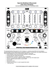
The Quad Pingable LFO (QPLFO) from 4ms Company is a compact, playable four-channel tap-tempo, pingable
(clock-syncable) LFO with variable skew and reset. Each channel's speed is set by a Tap Tempo button or an
external clock (Ping). Each channel can be Muted with a latching button and Reset with an external trigger. The
Skew CV and knob allow for a variety of waveshapes without losing sync to the ping clock. A plethora of headers
allows for connection to other modules, including the 4ms Quad Clock Distributor, the 4ms VCA Matrix, the 4ms
SISM, and the Toppobrillo Mixiplexer. Several advanced features are hidden within the QPLFO: Floating Reset
mode, one-shot mode, "mutli-shot" mode, Fire-on-unmute, Bipolar/Unipolar outputs, and more...
The QPLFO is designed to be useful in small portable systems that require maximum functionality in minimal
space, as well as large systems that need maximum modulation sources.
The QPLFO has a variety of uses:
• Four LFOs with mutes
• Master tap clock
• Clock delay (Clock phase shifting)
• Quadrature LFO
• Square/Pulse to Triangle/Ramp waveshaper
• One-shot
DOWNLOAD MOST RECENT MANUAL AT:
http://4mspedals.com/qplfo.php
Basic features:
• Quad “pingable” LFO's – frequency is set by time between pulses ("ping")
• Each of the 4 channels is an independent LFO
• Can produce a variety of waveshapes: triggers, to near-expo "pluck", to ramp-down, to triangle, to ramp-up, and all
shapes in-between
• Channels can easily modulate, trigger, and reset each other for complex and slowly morphing outputs
• Slowest period is 71 minutes (0.0002 Hz), fastest speed is about 500Hz (marginal tracking up to 1kHz)
• Tap tempo button is free-running (LFO runs indefinitely), but external clock/Ping is auto-stopping (LFO stops when
external clock stops)
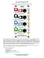
Controls and jacks:
•
•
•
•
•
•
•
•
•
Tap tempo button ("Ping") for manually setting the tempo
Ping jack sets tempo with an external clock (any signal can be used)
On/mute button enables or mutes the output (latching button)
Skew knob and CV jack control the waveshape by altering the ratio between rise and fall times
• At 0% Skew (0V of CV), the shape is a 10ms trigger
• At 1% Skew is a near-exponential "pluck"
• As Skew increase to about 3%, it becomes less exponential and more linear
• At about 3% Skew, the shape is linear ramp-down
• At 50% Skew (about 5V of CV), the shape is triangle
• At 100% Skew (about 10V of CV), the shape is ramp-up
• Skew knob provides offset to the incoming CV signal, so any range of CV is acceptable
Reset jack restarts the LFO without changing the tempo (rising edge triggered)
OUT jack outputs either a 0 to 10V waveshape, or a -5V to +5V waveshape (jumper selectable)
LED flashes and dims to the signal on the OUT jack
Tap tempo button flashes to the internal tap-tempo clock or to incoming pulses on the Ping jack
On/Mute button lights up when channel is On
Advanced
• Ping and Reset inputs use comparators, so any waveshape can be used for triggering (audio waves, complex LFOs,
even the QPLFO itself!)
• Trim-pot on PCB allows for adjustment of comparator threshold value
• "Fire-on-unmute" jumper per channel:
• When this optional jumper is installed, pressing the On button to turn the channel on will reset the LFO.
• If the jumper is not installed (factory default), pressing On will unmute the LFO without resetting (LFO runs in
the background when muted)
• Bipolar/Unipolar jumper:
• Setting jumper to Bipolar makes the outputs -5V to +5V
• Setting jumper to Unipolar makes the outputs 0V to +10V
• One jumper controls all four channels
• One-shot mode: Reset jack can be used to trigger a one-shot envelope if the external ping clock is stopped. See
section below for detailed discussion
• Floating Reset mode: Holding a high gate on Reset jack allows the waveshape to run freely without automatically resyncing to the ping clock. A bare cable plugged into the jack causes a high gate
• Connects to other modules using ribbon cables:
• Outputs can connect to the 4ms VCA Matrix, or the 4ms SISM, or the Toppobrillo Mixiplexer
• Normalization of ping jacks can connect to the 4ms Quad Clock Distributer
Dimensions
•
•
12 HP Eurorack format module
1.57” (40 mm) deep
Power consumption
+12V rail:
89mA max with 5V Source jumper selecting external 5V
154mA max with 5V Source jumper selecting internal 5V
+5V rail:
65mA max with 5V Source jumper selecting external 5V
not used with 5V Source jumper selecting internal 5V
-12V rail:
73mA max
Page 2
Your first QPLFO patch
The QPLFO is a different kind of LFO than you might be used to. Rather than setting the speed with a knob and/or CV jack
like a traditional LFO, the QPLFO sets the speed by using an external clock or tap button. To do anything with the QPLFO you
first need to give it a Ping. Let's get started with your first patch:
1. Start by tapping in a tempo on the red channel: just press the top Ping button twice
Instantly, the button will flash to your tempo, and keep running.
2. Press the On button and it will light up orange.
When this button is off, the channel is muted (no output).
The Ping button will continue to flash even if a channel is muted,
so you can see what tempo it'll be when you unmute it
3. Plug the OUT jack into something you want to modulate (try the pitch of a VCO, or run one VCO into a
VCA and then into the FM of another VCO, and use the QPLFO to open up the VCA).
When the On button is lit up, notice that the LED by the OUT jack will also be flashing.
The brightness of this LED follows the signal of the output.
4. Play with the Skew knob and listen to how the waveshape changes. Notice how the total frequency (or
period) of the output does not change. Technically, Skew sets the ratio between the rise and fall times without
changing the total time.
For most of the range, the waveshape will be linear rise and fall.
But when Skew is at 0%, the output will be a sharp attack with sharp drop-off... similar to an expo curve
(technically it's a quadratic curve). If you nudge Skew up just a hair, it will output a linear Ramp-down sawtooth
shape. At center it will do a Triangle wave. All the way up, you get a Ramp-up shape.
Now try sync'ing the QPLFO channel to an external clock.
Plug a clock, or anything, into the Ping jack. Maybe an RCD or SCM output, or the output of
another LFO or cycling envelope, or a VCO at a very slow speed.
The Ping button will light up when a signal is present on the jack, and will switch from running
at your tap-tempo to the incoming clock's tempo.
Next, let's play with Reset. Plug a manual gate/trigger (or a really slow clock) into the Reset jack.
The LFO will start over each time it receives a signal on this jack.
(See below for a technical description of what Reset is actually doing.)
Now try a fun trick: modulate Skew of one channel with another channel's output.
Set the red channel tempo to about 1-3 cycles per second.
Tap the blue channel's Ping button once. Listen to the red channel make 8 cycles, and
then tap the blue Ping a second time.
Plug the blue channel output into the red channel Skew CV jack.
Turn the red channel Skew knob all the way down.
Turn blue channel Skew to triangle (center).
You should be hearing the red channel skew shift from falling ramp to triangle to rising
ramp.
You can mute the blue channel to make the red channel go back to a static waveshape.
If you want to get chaotic, mult or stack the red channel output, and plug it back into the blue channel's Skew. Keep going, try
chaining all 4 channels together, plug into Reset and Ping, it's easy to get crazy quick...
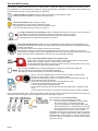
Here's another fun trick: One-shot mode.
First, you have to arm it by stopping your clock:
• If you're running an external clock into Ping, either
stop it at the source, or unplug the Ping jack.
• If you're using Tap tempo, then tap the button three
times and hold it down on the third time for 2 seconds.
• The orange button should be lit up (unmuted) but the
channel should not be running. This is "armed."
To trigger a one-shot, give a pulse on the reset jack. You can
plug Reset into a trigger pad (Synthwerks FSR, or Makenoise
Pressure Points, or FoH Choices...). Hint: in a pinch you can
use a bare cable by touching the tip to metal (cheap and dirty
hack, but it works!)
Page 3
Example Patches
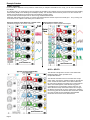
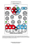
Tempo syncing:
If you want all the channels to be synced to a master clock (or multiples and divisions of a clock), you can use a clock divider
or multiplier.
In a small system, you might want to use one channel of the QPLFO as a master clock to clock such devices as the Rotating
Clock Divider (RCD) or the Shuffling Clock Multiplier (SCM). Turn the Skew knob all the way down to use the channel as a
master clock (this produces an output that's somewhat like a trigger pulse).
Any of the RCD or SCM outputs can be used to Ping and Reset the QPLFO.
Advanced: After setting up this patch, try running the slowest QPLFO channel output to the Rotate jack... Or try running one
of the slower clock outputs to the Reset jack of a faster LFO
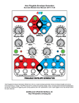
Using one channel of the QPLFO as a master clock: Using an external master clock:
(with RCD pinging the other three channels)
with shuffle/slip to create complex waveshapes
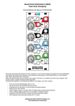
QCD + QPLFO
The QPLFO is designed to connect to the Quad Clock
Distributer (QCD), which provides clock
multiplication/division.
The QPLFO and QCD connect in the back with a 8-pin
ribbon cable. Connect the "PINGS" header on the QPLFO
to the "CLOCK OUTS" header on the QCD. Make sure
the red stripe is aligned to the white line on both modules.
When connected together, each QPLFO Ping jack is
normalized to the corresponding channel output on the
QCD. Whatever tempo each QCD channel is running at,
the QPLFO channel will run at the same tempo. Plugging
into the Ping jack will override the QCD connection, so the
two units can still be used separately. More detailed
information will be found in the QCD manual.
Page 4
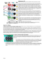
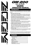
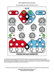
Quadrature LFO
There's several ways to generate quadrature with this quad LFO module.
A. The most clever method uses the QPLFO by itself. This method takes
advantage of the trimpot on the back of the QPLFO, which sets the threshold
voltage for the Ping and Reset comparators. Adjust this trimpot so the
threshold voltage is 5V (all the way up), assuming you are set to Unipolar
outputs (0 to 10V). Now patch channel 1's output to channel 2's Ping input,
channel 2's output to channel 3's Ping, and channel 3's output to channel 4's
ping. Tap a tempo on channel 1 or use an external clock. The four channel
outputs will be 90 degrees out-of-phase from each other, in quadrature (you
need to stack/mult the outputs for channels 1-3).
B. Another way is to first make a quadrature clock, and then feed that into
the QPLFO's ping inputs. There's various ways to make a quadrature clock.
An A-151 or other sequential switch is and easy way, just run a steady high
voltage into the common (O/I) jack and patch the four I/O jacks to the
QPLFO pings. Clock the A-151 as normal. Or you can use an RCD that's reflashed as a Triggered Gate Sequencer. Also, an A-152 provides quick
quadrature clock outputs by using Dig.Outs jacks 1-4, and patching jack 5 to
Reset.
C. Another way is to use the Reset jacks. This method doesn't give perfect
90 degrees, but it does allow you to "feel" out the desired phase difference
and change each channel's phase offset independantly and on-the-fly.
1. Ping all the channels with the same external clock (stack/mult to all four
ping jacks)
2. Run a manual gate into each Reset jack.
3. Fire a trigger into each gate at the appropriate time, approximately a
quarter of the way through the previous channel's cycle.
Quad VCO FMing
It might not be hard to find four things to modulate with the QPLFO, but if you need something to try out, the following patch
creates an endless variety of complexly changing sounds.
Run the outputs of four VCOs into the inputs of a VCA Matrix. (If you only have 3 VCOs, or even 2, the patch will still work!)
Run the VCAM outputs into the FM or 1V/oct inputs of the same four VCOs (try to keep them in the same order: A->1, B->2,
etc). Pick four different CV-jacks on the VCAM and plug in the outputs from the QPLFO. At first, try to avoid the CV-jacks that
feed a VCO back into itself (A1, B2, C3, D4), these are less interesting.
As the LFOs cycle, the VCA Matrix creates different permutations of VCOs FM'ing each other. Mute/unmute LFOs and VCAM
channels at will, and play with the VCAM attenuators. Since this can quickly get out of control, try keeping the four QPLFO
channels synced to a master clock (see Tempo Syncing patch). Using the plucky skew setting gives intense percussive
effects, and triangle skew is nice to slowly bring in a sound. Modulating Skew slowly is also great.
Connecting LFO outputs to other modules with 8-pin header
The QPLFO has an 8-pin header labeled "OUTS" that outputs the LFO signals (0 to +10V).
This can connect to other modules for behind-the-scenes connectivity. The On/Mute button
stays active, the signals on the header pins are literally the same signals that are on the
OUT jacks.
•
•
•
Page 5
4ms VCA Matrix: use the "DAISYCHAIN INPUTS" header. The LFOs appear on the
main input jacks (not the CV jacks). This is extremely useful for routing combinations
of LFOs to various places in your patch. Note: to minimize clipping, use the QPLFO
in Bipolar +/-5V mode when connecting to the VCA Matrix or any DC mixer.
4ms Shifting Inverting Signal Mingler (SISM). Details forthcoming in the SISM manual.
The Mixiplexer from Toppobrillo accepts this cable with a special mod board. Pressing the X/I button on the Mixiplexer
selects the QPLFO's four LFOs to control the four VCAs of the Mixiplexer. Level knobs on the Mixiplexer attenuate the
LFOs, and the mute buttons on the QPLFO can mute the channel. The Slope parameter on the Mixiplexer is also
active.
Detailed Discussions and Special Features
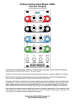
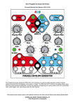
Skew curves
10ms trigger pulse
Skew at <200mV (7:00)
Quadratic root curve ("pluck") Cubic root curve ("pluck")
Skew at ~300mV (7:25)
Skew at ~400mV (7:30)
Ramp-up: Skew at ~600mV (7:40)
Triangle: Skew at 5V (12:00)
Square root curve ("pluck")
Skew at ~500mV (7:35)
Ramp-up: Skew at 10V (5:00)
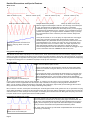
Skew changes the waveshape in real-time. The full range of the Skew jack
is 10V. The Skew knob provides offset for the jack. For maximum
modulation range, turn the Skew knob all the way down if you are plugging
in a positive-only modulation source. Likewise, if your modulation source is
positive and negative, you will get maximum modulation range if you keep
the knob towards the center. These are just rules of thumb, always trust
your ears.
Modulating Skew with an external CV.
Output in red (top), Skew CV in blue
(bottom).
At 0% (Knob at CCW, or 0V on the jack), the output will be a 10ms trigger
pulse. This is useful for clocking other devices (drum modules, clock
divider/multiplier, etc). With Skew turned up just a hair, there will be a nearexponential falling curve. Turning it up a tiny bit more, it will morph into a
linear ramp-down curve. From here to 100%, the output stays linear: the
skew will smoothly transition from ramp-down to triangle to ramp-up.
One interesting feature is that the QPLFO won't switch to the trigger or expo
curves unless Skew was near 0 before the start of the curve.
Ping jack and Ping button
The QPLFO can use either a tap-tempo or an external clock, and it switches between them automatically. Tapping a tempo
with the Ping button enables the tap-tempo circuit, and the Ping button will flash to the tempo of the internal clock. As soon as
an external signal is recognized on the Ping jack, the internal tap-tempo clock is turned off, and the Ping button will displaying
the signal on the Ping jack. To re-enable the tap tempo circuit, tap in a new tempo.
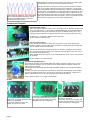
One-shot mode
See "Your first QPLFO patch" section.
The key to this mode is to set a Ping time, then let the clock expire (which
stops the LFO without muting the channel). You can fire the One-shot with
the Reset jack.
If you're using tap tempo, just hold the Tap button down for 2 seconds. This
tells the QPLFO to stop the internal tap clock. To avoid double-triggering or
weird intermediate tempos, you may want to tap the tempo immediately
Top: output (one-shots)
before holding the button down for 2 seconds, thus we recommend "Tap-TapBottom: Triggers into the Reset jack
Hold".
If you're using external clock: stop the clock upstream, or unplug it (or mute it with a VCA, for example). The QPLFO will
notice that the clock is stopped and force the output to stop. However, the timing from the ping will be remembered.
(Note: you can mute the channel and still give it a ping/tap. This prevents any output while you are setting up the one-shot
timing. Unmute the channel when you're ready to start firing reset pulses)
Next, To fire the one-shot, send a pulse into Reset jack. A manual gate module works great for this. Or, a quick hack is to plug
a bare cable into Reset: it will fire a one-shot envelope if the other end of the cable is unplugged. You also can touch the bare
end of the cable on some metal (the nut of the jacks, for example) and it will fire each time. Doing this isn't pretty, but it works
in a pinch and/or can be a great space-saver for small systems.
Clocked Reset ("Multi-shot" mode)
Set up the ping/tap timing as described in the One-shot mode patch. The
QPLFO should be unmuted, but not running. Now plug a clock into Reset. The
length of the output waveshape will match the timing obtained from the ping or
tapping, but the frequency of the output will match the frequency of the Reset.
Thus you can fire short bursts with a pause/silence between pulses.
Top: multi-shot output
Bottom: Clock on the Reset jack
Page 6
Hint: If this output is inverted, you will obtain a trapezoidal wave whose shape is
set entirely by clock timing.
What exactly is Reset? What is the Reset Lock Point?
Can I do clock phase shifting with the QPLFO?
Reset on the QPLFO behaves the same as reset on a traditional/typical
LFO: it re-starts the LFO when a trigger is received on the Reset jack.
However, there are some unique subtleties to the QPLFO.
When you first power the QPLFO on (without having given a reset pulse),
the output waveform always starts at the same moment the Ping button
lights up. Try setting a slow tempo, about 3 seconds or so, and turn Skew
all the way down. See how the LED by the output jack and the Ping button
light at the same time? This means that they are in-phase. See in the
diagram (left), the first few triangle waves all start on the ping's rising edge:
they are in-phase.
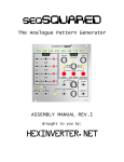
Bottom trace is ping (20ms period)
First four waveshapes start on the Ping. Then
a reset pulse is applied about 8ms after a
Ping. This defines the Reset Lock Point (8ms
after each Ping). Subsequent waveshapes all
start on this Reset Lock Point
Reset changes the phase relationship between the incoming Ping and the
output. Let's say your incoming Ping is a clock that marks the start of a
measure. By default, the LFO will begin at the start of each measure (ONE
two three four). But, if you give a reset pulse mid-way through the
measure, the LFO will begin at this point mid-way through the measure
(one two THREE four). It will keep resetting/re-starting when this point in
the measure happens, until/unless you assign a different reset point.
This point in time is called the "Reset Lock Point" and it's measured in the amount of time to delay the start of the wave after
a ping is received. The QPLFO will make sure the output always is synced to this Reset Lock Point, unless you tell it
otherwise. See the diagram: after a Reset pulse is given, the triangle waves always start at a point to the right of each ping's
rising edge. This feature is a critical difference between the QPLFO and other/traditional LFOs.
Note that the Reset Lock Point is relative to the ping. If you change the ping time (by tapping in a different tempo, or changing
the speed of the external clock), the reset will stay the same in terms of length of time (not in proportion of time). So if you
give the QPLFO a reset pulse 500ms after the ping, the LFO will always start 500ms after the ping, even if you slow the ping
time down. If you change your clock speed (ping time) to faster than 500ms, then the reset time will be meaningless and by
default it will be set to 0ms (in-phase with Ping). This is a quick way to clear the Reset Lock Point: speed up your clock, then
slow it back down again. Another way is to give a reset pulse at the same moment as the ping (either manually, or plug the
ping clock into the reset jack).
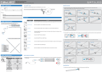
Floating Reset mode
Bottom trace is Ping clock. Skew is being
modulated manually. Reset is being held high to
put us in Floating Reset mode. Notice how
output does not always start on the Ping.
Holding a gate high on the Reset jack tells the QPLFO to stop
resetting/re-syncing your waveshape on each Ping or Reset Lock Point.
This is called "Floating Reset mode" because the LFO will not reset to a
specific lock point. Nothing else changes in Floating Reset mode: the
Ping is still actively creating the timing of the output: if the ping clock
stops, the output will still stop; and if the ping clock speeds up or slows
down, the output will still speed up or slow down.
In a small system you might not have a steady high gate handy, so you
can simply plug a cable into the Reset jack and leave the other end
dangling (or plugged into another channel's Reset jack). A reset pulse will
occur when you plug a bare cable in, and you have entered Floating
Reset mode.
Floating Reset mode might not be noticed by a casual user, but it does have some important (though subtle) uses.
For example, the QPLFO will slowly drift off time with an external Ping in Floating Reset mode. Often this is not desirable, but
for some works of music this is an interesting (perhaps crucial) element.
Another use for Floating Reset mode is if you want to modulate the phase by changing Skew instead of giving Reset pulses.
This will completely avoid any sharp re-syncing that would occur if you changed phase with Reset triggers. Since the
automatic reset at the Reset Lock Point or Ping is disabled in Floating Reset mode, you are free to twiddle skew without any
attempt by the QPLFO's to sync you back to a clock. As the output changes period when its Skew is modulated, the result is
that after you are done turning Skew, the output will have a different phase.
Skew modulation suspends automatic resetting/re-syncing (unless you tell it not to)
This feature happens automatically in the background and is not necessary to understand, even for advanced users.
Normally, when no skew modulation is happening, the output will be reset automatically when a ping is received (or the Reset
Lock Point occurs, see "What exactly is Reset" section). An interesting feature of the QPLFO is that this automatic
resyncing/resetting is disabled if Skew is actively being modulated (e.g. you are turning the Skew knob). This is similar to
Floating Reset mode, but it only lasts as long as Skew is changing value.
Why? When you turn the Skew knob, it might take you a fraction of a second or so to turn the dial. During this fraction of a
second, the waveform is changing shape while tracking the knob. Since it's changing shape, it's also changing period and
phase. Trying to re-assign phase while phase is changing is counter-intuitive and results in weird artifacts (double-hits and
false starts). It's better to reset/re-sync when you're done changing the shape. So by disabling the automatic reset feature
while Skew is being modulated, the QPLFO feels more friendly and it "just does what you think it will do". As soon as a Skew
Page 7
holds steady for a fraction of a second, the auto-reset is re-enabled and it
will snap back in sync at the next Ping or Reset Lock Point.
Delving further into the nitty-gritty of timing, you can override this feature.
Let's say your patch requires resyncing 100% of the time, on every beat
without compromises, and at the same time you want to modulate skew all
over the place. Just mult/stack your ping clock into the Reset jack (or send
some other clock into Reset if you want phase shift). A pulse received on
the Reset jack will force a reset to occur, even if Skew is being modulated.
Bottom: Ping (for reference). Top is output while Again, this "just does what you think it will do", but if you've made it this far
skew is being modulated continually, starting
in the manual, you deserve to know what's really going on!
with the second triangle wave. Notice how
period and phase are variable.
Jumpers and Trimpots
Bipolar/Unipolar jumper
This jumper selects "Bipolar" output (-5V to +5V waveforms), or "Unipolar" output (0V to
+10V). On PCB version 1.0, the jumper is labeled "BIPOLAR" on the left side. Putting
the jumper between the left pin and center pin gives you Bipolar mode (-5V to +5V).
Putting the jumper between the right pin and center pin is Unipolar mode (0V to 10V).
On PCB v1.0.1, the jumper is labeled +/-5V and 0/+10V.
Factory default is Unipolar mode.
Fire-on-unmute jumpers
Each channel has a jumper to enable "Fire-on-unmute" mode. These jumpers are
located in between the two PCBs, above the buttons. Installing the jumper enables the
Fire-on-unmute mode for that channel.
In this mode, turning the On button from off to on will fire a quick pulse into the Reset
jack. This will reset the waveform. This is useful for using the QPLFO as a one-shot, or
for manually re-syncing the LFO.
Each channel has its own jumper, so you could enable this on all, none, or only some of
the channels.
Factory default is no jumpers (all off).
Threshold Trimpot Adjustment
The trimpot on the back of the QPLFO adjusts the voltage required to trigger a ping or reset.
At fully CCW, the voltage is 5.0V. At center, it's 2.5V. At fully CW it's 0V and the unit will not
respond to Ping or Reset.
The QPLFO can be interfaced with LZX-level compatible equipement by setting this trimpot to
about 0.8V.
It's safe to turn the trimpot with the unit powered up, but normal cautions apply when handling
any piece of equipment that's "live". You can use a volt meter to measure the voltage on the
wiper of the trimpot as you turn it. This voltage will be the threshold voltage.
Factory default is about 2V, or roughly near half-way.
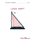
Headers
Reserved for future use.
In the initial release firmware, jumping
LFO outputs: connects to 4ms VCA
Matrix Input, Toppobrillo Mixiplexer (with pins makes each channel free-running
(disables auto-stop of Ping clock).
adaptor), or 4ms SISM.
In the photo, the bottom row is the
signals, the top row is ground
Page 8
Ping jack normalizations.
Connects to 4ms QCD.
In the photo, the top row is ground, and
the each pin on the bottom row connects
to the normalization of a Ping jack.