1
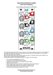
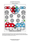
4ms SCM BREAKOUT PANEL
expansion module for the Shuffling Clock Multiplier
User Manual v1.0
http://www.4mspedals.com/scm.php
Features
• Expansion module for the 4ms Shuffling Clock Multiplier:
• CV Shuffle (jack and knob)
• Selects which beats are “slipped” by CV Slip
• CV Skip (jack and knob)
• Omits certain beats in a pattern
• CV Pulse Width (jack and knob)
• Controls width of output pulses
• 4x Fast (jack and switch)
• CV gate or manual switch speeds up all jacks by a factor of 4
• Mute (jack and switch)
• CV gate or manual switch stops any more pulses from starting
• All pulses that have already started will end normally
• Re-sync CV Trigger input jack
• Resets beat pattern to beat one
• Additional CV Rotate and CV Slip jacks
• Adds to the main panel's Rotate and Slip jacks
• 8 H.P. Eurorack module
• Connects directly to the SCM with a standard 16-pin cable (same cable used
for Eurorack/Doepfer style power connections)
• SCM Breakout does not connect directly to the power rail
I. Installing the SCM Breakout
The SCM Breakout connects to the main SCM with a 16-pin Doepfer-style power cable.
First, remove the six jumpers from your SCM's “BREAKOUT” (pcb version 1.0.2) or “JUMP/B-O” (pcb version 1.0.3) header.
The jumpers are not needed any more.
Now look carefully at the main SCM's “JUMP/B-O” or “BREAKOUT” header. Also look at the 16-pin header on the SCM
Breakout board. Notice that on both boards there's a small white box printed next to one pin (the pin itself may have been
removed). When you connect the cable between the two modules, make sure the red stripe of the cable is orientated towards
the white box on both units.
NEVER CONNECT THE SCM BREAKOUT MODULE DIRECTLY TO A POWER DISTRUBUTION BOARD! The SCM
Breakout only connects to an SCM, and never directly to the power rails. Although it uses the same cable used for eurorack
module power connections, the SCM Breakout DOES NOT CONNECT TO THE POWER RAILS on your modular system.
Instead, it draws power from the SCM module itself (very little current is consumed).
Remove the jumpers and connect the red stripe of the cable to the side
closest to the white square on both the main SCM and the Breakout
II. Operation
Getting Started
The knobs on the SCM Breakout rotate from about 4o'clock at minimum to about 2o'clock at maximum. The center of each
knob's range is at 9o'clock.
A good way to start is to first turn the knobs to their default settings: Shuffle, Skip, and Rotate all the way down (counter/anticlockwise); Slip and PW turned to center. Also, flip both switches to the right so that 4x Fast and Mute are not engaged. This
is the default setting for an SCM with all the jumpers set and nothing plugged into Slip or Rotate.
After getting a feel for the knobs, try running a CV signal into one of the jacks. Rotate or PW might be good choices to start
with. Try running a very slow triangle wave into the one of these jacks (about 2-5 seconds per cycle) and watch the lights
and/or listen to the SCM trigger/gate things differently. If you're modulating PW, you should see the lights stay on longer and
longer as the triangle rises, and then get shorter and shorter as the triangle falls.
A fun sample patch to try next is to trigger a Low Pass Gate (Borg Filter, or Model 13 DTG) with the x8 jack and another
similar LPG/etc with the S8 jack. Run an oscillator or some sound source into both LPGs and mix the outputs together so you
can hear both at the same time. Now on the SCM Breakout, turn Rotate, Shuffle, and Skip all the way down. Turn PW to 50%
and adjust to suit your ears. Now play with Slip, slowly turn the knob along its full range and listen to how every other beat
from the S8 jack lands later and later as you turn Slip up. Now nudge Shuffle up until the beat pattern changes. Play with Slip
some more... keep nudging Shuffle up and playing with Slip. Once you get a feel for all the possibilities with those two knobs,
start playing with the Skip knob: you should hear some beats drop out of the S8 sound but the x8 will continue thumping
steadily along.
Using CV and the Knobs at the Same Time
To modulate a parameter, you can simply turn the knob until you get the desired result. Also, you can feed a CV signal into
the associated jack: the signal applied to the CV jack will be added to the setting of the knob. Another way to say this is that
the knob controls the DC offset of the CV signal, and the CV signal is DC coupled to the circuit. The result of this addition of
the knob and CV input is then clipped to the range of 0V to 5V, which is the operating range for the SCM.
What this means is that you don't have to limit your incoming CV signals to 0V-5V: any positive or negative signal
between -12/15V and +12/15V may be useful! For example, feed a slow triangle or ADSR-type waveshape from a
Bananalogue VCS or a Makenoise MATHs or any Doepfer A-14X into the PW jack. With the PW knob at minimum, only the
positive half of the incoming waveshape will increase the pulse width, and the negative half of the waveshape will be ignored.
If you turn the PW knob to center, then the positive part of the waveshape will make the PW increase, and the negative part
of the waveshape will make the PW decrease. If you turn the PW knob all the way to maximum, then only the negative part of
the waveshapes will have an effect (they'll make the PW decrease from maximum) and the positive half of the waveshape
will be ignored.
Strange interaction note! When feeding the Wiard/Malekko Envelator's “+” output directly into a CV jack on the SCM
breakout, the corresponding knob should be turned all the way down. A very useful and full range of modulation can be
obtained this way, as long as the knob is kept at 0%. Turning the knob up may alter the Envelator's oscillation. Running the
Envelator into a buffer or VCA before the SCM avoids this.
Using the Flip Switches
The 4x Fast jack and the Mute jack are normalized to their associated flip switches. So, by plugging something into the jack,
the switch is disabled. Applying a gate signal of at least 3V to the jack will cause the feature to turn ON. You can even input a
complex waveshape and the feature will turn on and off as it crosses the 3V threshold.
III. Description of Controls
CV Shuffle
CV Shuffle is closely related to CV Slip, which is described in the main SCM manual (download from
http://www.4mspedals.com/scm.php). While Slip controls the amount that certain beats are pushed forward in time, Shuffle
controls which beats are slipped. The default setting is every other beat (Shuffle at minimum). As you turn Shuffle up, first
every third beat will be slipped, then every fourth beat, fifth, sixth, and finally at about the middle of the knob's range, every
seventh beat will be pushed forward.
From the middle of the range to the maximum, Shuffle behaves differently. Instead of pushing just one beat forward, it
pushes groups of beats forward. So at first a group of two beats are slipped, then a group of three, etc...
CV Skip
CV Skip is used to drop beats out of each measure. The concept of the measure is based on 8 beats. The jacks that output
less than x8 are considered to be the first “n” beats of the measure (e.g. S5 jack is considered to be the first 5 beats of a
measure).
With Skip at minimum, all beats are played. As you turn the Skip knob up or apply a positive CV, more and more beats will be
dropped out. The pattern of dropped beats is determined by a lookup table in the SCM's code. Each CV voltage corresponds
to a particular pattern in the lookup table. There are 128 entries in the table, which range from 0 beats dropped, to each one
of 8 beats dropped, to every permutation of 2 dropped beats, to every permutation of 3 beats dropped, to (nearly) every
permutation of 4 beats dropped out of an 8-beat measure. Then the table is inverted, so that it continues to 5, 6, and 7 beats
dropped. Dropping all 8 beats is avoided, since the Mute feature has this same functionality.
CV Pulse Width (PW)
Pulse Width is a very useful feature that affects all 8 output jacks. With PW at minimum, each jack will output a very short
pulse, about __ms. This is enough to trigger most other modules, but no more than necessary.
As you increase PW to about the knob's center setting, the pulse width will be 50%, which is a nicely balanced square wave.
At this setting, the amount of time the waveshape spends being low (0V) is equal to the time it spends being high (+10V).
This is a fairly useful setting for getting started with learning the SCM.
At its maximum setting, the pulse width becomes very long, in that it only blips low for __ms. This is functionally an inverted
trigger. One thing to watch out for with a very long pulse width is that the Slip/Shuffle effect will have only a very small effect.
This is because Slip/Shuffle pushes the beats forwards in time without changing their pulse width. So when the width of the
pulse is very long and the gap between the pulses is very short, there isn't much room to move without completely closing
the gap between pulses. Therefore not much slipping can occur. To best hear the Slip/Shuffle effect, keep PW at 50% or
less. Another way to think about this is that PW is a CV way to decrease the amount of Slip effect without changing Slip itself.
However you use it, watching the lights flash is a good way to see what PW is doing.
4x Fast
Like it's name says, flipping the switch to the left or applying a gate voltage greater than 3V will make every jack go four
times as fast. One quick and fun patch is to connect one of the SCM outputs to the 4x Fast input (e.g. try the x2 jack). When
the jack goes high it will speed everything up, including the jack itself, so when it quickly flips low, everything slows down...
this is a very simple way to create a chaotic rhythm pattern. Playing with PW dramatically effects the pattern.
Mute
Mute is a very simple and useful feature: flipping the switch to the left, or applying a gate voltage greater than 3V will prevent
any new jacks from turning ON. Any jack that's already outputting a high signal will continue on its normal timing, but when it
goes low it will stay low as long as the Mute gate is held high.
This is the easiest way to kill the “light show” on the SCM. But more useful (and blinding) is patching an SCM output to the
Mute jack. When the jack goes high, no new jacks will turn on, but when that jack goes off, normal play resumes. This drops
out beats in a rhythmic semi-deterministic way. Like patching to the 4x Fast jack, playing with PW will effect the pattern
dramatically.
Resync
Applying a CV Trigger (>3V) to this jack will cause the beat pattern to start over. The beat pattern is established by Skip, Slip,
and Shuffle.
CV Slip
The CV Slip jack on SCM Breakout adds to the voltage of the main SCM's CV Slip jack. Both jacks can be used
simultaneously, along with the Slip knob.
See the SCM manual for a description of CV Slip.
CV Rotation
The CV Rotate jack on SCM Breakout adds to the voltage of the main SCM's CV Rotate jack. Both jacks can be used
simultaneously, along with the Rotate knob.
See the SCM manual for a description of CV Rotation.