1
Freescale Semiconductor
Document Number: AN2336
Rev. 2, 12/2006
Application Note
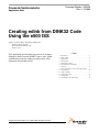
Creating edink from DINK32 Code
Using the e500 ISS
Authors: Amanuel Belay and Maurie Ommerman
Digital Systems Division
Freescale Semiconductor, Inc.
Austin, Texas
This application note describes the process of creating a
debugger (edink) from the DINK32 source code. It then
explains how to run the edink executable on the e500
Instruction Set Simulator (ISS).
© Freescale Semiconductor, Inc., 2004, 2006. All rights reserved.
1.
2.
3.
4.
5.
6.
7.
8.
9.
10.
11.
12.
13.
Contents
Introduction . . . . . . . . . . . . . . . . . . . . . . . . . . . . . . . . . 2
What is edink? . . . . . . . . . . . . . . . . . . . . . . . . . . . . . . 3
edink Startup . . . . . . . . . . . . . . . . . . . . . . . . . . . . . . . . 3
Memory Map . . . . . . . . . . . . . . . . . . . . . . . . . . . . . . . 4
Stack Space for edink . . . . . . . . . . . . . . . . . . . . . . . . . 5
e500 Instruction Set Simulator . . . . . . . . . . . . . . . . . . 7
Compiler . . . . . . . . . . . . . . . . . . . . . . . . . . . . . . . . . . . 9
e500 Core Registers versus Classic PPC Registers . . 9
Code Changes . . . . . . . . . . . . . . . . . . . . . . . . . . . . . . 10
edink Availability . . . . . . . . . . . . . . . . . . . . . . . . . . . 11
edink Splash Screen . . . . . . . . . . . . . . . . . . . . . . . . . 11
Example Run . . . . . . . . . . . . . . . . . . . . . . . . . . . . . . . 12
Documentation Revision History . . . . . . . . . . . . . . . 14
Introduction
1
Introduction
This document describes the method and coding for the e500 edink program running on the e500 ISS.
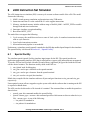
1.1
Terminology
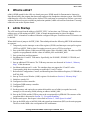
The following terms are used in this document.
Bash shell
Extension to the Bourne shell, which is popular on Linux systems and is
sometimes called GNU Born Again Bourne Shell. This is the default shell for most
Linux systems because Linux uses GNU tools exclusively. This is the best shell
running the ISS.
Boot
Program that begins at hardware reset, which prepares the hardware for loading
an operating system
Boot address
Address from which the board will attempt to boot after reset
BR
Compiler
CPU
DDR
DINK32
edink
Host
ISS
LAW
MARS
OR
OS
PCI
RAM
Scrub memory
SDRAM
Base address register
A software program that converts a high level source code into machine-specific
binary
Central processor unit, that is the e500 processor
Dual data rate SDRAM
Small operating system debugger for the Sandpoint evaluation board
Small operating system debugger for the e500 processors and the MARS platform
A machine that can be used to build kernels. The host may or may not be the same
architecture. For example, Freescale builds kernels on G4 machines, UNIX
machines, and Intel machines.
A software model that simulates instruction processing capability of a processor
Local access window
Evaluation board platform for the MPC8540 and MPC8560 processors
Option register
Operating system
Peripheral component interface
Random access memory
Setting memory with known values
Synchronous dynamic RAM
Creating edink from DINK32 Code Using the e500 ISS, Rev. 2
2
Freescale Semiconductor
What is edink?
2
What is edink?
edink is DINK ported for the e500 core based processors. DINK stands for Demonstrative Interactive
Nano Kernel and is the program that boots and configures the Sandpoint evaluation system. Like DINK,
edink boots the e500 core, enables caches, defines TLBs, and jumps to a prompt loop. Before a processor
with an e500-based core was available in production quantities, edink was tested on a simulator. Currently,
edink also runs on the Elysium board.
3
edink Startup
The e500 core boots from the address of 0xFFFF_FFFC. At boot time, one TLB entry is defined for an
address space of 4K starting at 0xFFFF_F000. A branch instruction must be placed at address
0xFFFF_FFFC to branch to an address within the configured 4K space. From there more TLB entries can
be defined.
When edink boots it jumps to 0xFFFF_F000. Then edink performs the following MPC8540 initialization
in sequence:
1. Temporarily sets the interrupt vector offset registers (IVORs) and interrupt vector prefix register
(IVPR) to 0xFFFF_F000 so that if exception occurs it goes to a TLB covered area.
2. Sets up the PID registers. Edink uses the PID register value of 0x0000_0000. The other two PID
registers are programmed with the values of 0x0000_0001 and 0x0000_0002.
3. Sets up time base and decrementer.
4. Invalidates the L1 and L2 TLB entries. Specifically, the IL1MMU, IL2MMU, L2TLB4K, and
L2TLBCAM.
5. Sets up additional TLB entries. The TLB entry structures are discussed in Section 4, “Memory
Map,” of this document.
6. Invalidates and turns on L1 cache. The simulator does not support the L2 and L3 cache.
Consequently, edink does not attempt to enable the L2 and L3 caches.
7. Relocates the Configuration, Control, and Status Registers Base Address Register (CCSRBAR) to
0xFC00_0000.
8. Sets up Local Access Window (LAW) registers. For details see Section 4, “Memory Map.”
9. Initializes console I/O.
10. Configures local bus controller.
11. Configures DDR memory controller.
12. Configures PCI.
13. Scrubs memory and copies the exception table and the rest of edink (except the boot code,
startup.S) to low memory (RAM) starting at address 0x0000_0000.
14. Sets up the IVORs and the IVPR to point to the exception table in SDRAM. The structure of the
exception table is discussed in Section 5.1, “Exception Handling.”
15. Defines stack space. Stack space is described in Section 5, “Stack Space for edink.”
16. Sets up the MSR value to 0x0200_0000 and return from instructions (RFIs) to the main program.
The bit set in the MSR value corresponds to SPE enablement.
Creating edink from DINK32 Code Using the e500 ISS, Rev. 2
Freescale Semiconductor
3
Memory Map
4
Memory Map
Unlike processors that implement the classic PowerPC™ architecture, the e500 is based on the embedded
PowerPC architecture (Book E). These processors use TLBs rather than BAT registers. For a detailed
description of TLB entries and how to program them refer to the MPC8540 or MPC8560 processor’s
reference manual.
At reset, a 4K memory space is predefined starting at 0xFFFF_F000 with supervisor read, write, and
execute permission. This memory area is caching inhibited. The startup code (in ‘startup.S’) sets up the
processor, the TLBs (to enable more than 4K), the Local Access Windows (LAWs) to access internal
peripherals, and the corresponding embedded device setup.
Note that the CCSRBAR is relocated from the default 0xFF70_0000 to 0xFC00_0000.
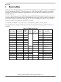
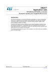
Once initialization is complete and the system has been setup, the memory map shown in Table 4-1 is
available.
Table 4-1. EDINK Memory Map
Start Address
End Address
Size
(MB)
TLB1
LAW
BR/OR
FF00_0000
FFFF_FFFF
16
0
0
0
Flash array #1
FE00_0000
FEFF_FFFF
16
1
Flash array #2
FD10_0000
FDFF_FFFF
15
—
Unused
FD00_0000
FD0F_FFFF
1
2
8K NVRAM
FC10_0000
FCFF_FFFF
15
—
—
Unused
FC00_0000
FC0F_FFFF
1
—
—
CCSRBAR
F000_0000
FBFF_FFFF
192
—
—
Unused
E000_0000
EFFF_FFFF
256
3
—
—
Unused; test
C000_0000
DFFF_FFFF
—
—
—
—
Unused
A000_0000
BFFF_FFFF
512
6&7
3
—
RapidIO I/O
9000_0000
9FFF_FFFF
256
5
2
—
PCI IO space
8000_0000
8FFF_FFFF
256
4
—
PCI memory space
2000_0000
7FFF_FFFF
—
—
—
—
Unused
0000_0000
1FFF_FFFF
512
1&2
1
—
DDR SDRAM
1
Description
Note that some address spaces require more than one TLB to be covered.
Creating edink from DINK32 Code Using the e500 ISS, Rev. 2
4
Freescale Semiconductor
Stack Space for edink
5
Stack Space for edink
Classic Dink R12.3 only had 0x0001_0000 = 65K decimal stack space, which was divided into four stack
memory spaces, Dink CPU0 and 1 and User CPU0 and 1. This allowed only 4K for each stack.
Stack space for classic dink R13.0 has been increased to 0x0004_0000 and is still allocated to four stack
areas. This allows 0x0001_0000 = 64K decimal for each stack space. This means that user code will start
at 0x0010_0000. Edink uses the same larger stack space for one CPU.
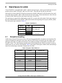
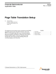
The stack space is setup before edink jumps to main. R1 is used as the stack pointer. Stack space starts at
the end of edink RAM location (0x000C_0000) and extends to the beginning of user space (0x0010_0000).
The stack space map is shown in Table 5-1.
\
Table 5-1. Stack Space
Address
5.1
ROM
0x000F_FFE0
Start of edink stack
0x000E_0000
End of edink stack
0x000D_FFE0
Start of user stack
0x000C_0000
End of user stack
Exception Handling
Unlike classic PowerPC based processors, e500 core has programmable exception vector locations. The
registers designate the interrupt vector offset while the IVPR register designates the start address of the
interrupt vector table. For edink, the interrupt vector addresses remain as compatible as possible with
PowerPC classic. The e500 interrupt vectors not previously defined by the classic processors occupy an
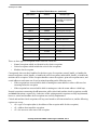
address that was not used by classic DINK. Table 2 shows the IVOR register, address offset and interrupt
name for each interrupt vector that is implemented in edink.
I
Table 2. Exception Table Addresses
VOR Number
Address
Interrupt Type
IVOR0
0x0100
Critical input
IVOR1
0x0200
Machine check
IVOR2
0x0300
Data storage
IVOR3
0x0400
Instruction storage
IVOR4
0x0500
External input
IVOR5
0x0600
Alignment
IVOR6
0x0700
Program
IVOR7
0x0800
Floating-point unavailable
(not supported on the e500)
IVOR10
0x0900
Decrementer
Creating edink from DINK32 Code Using the e500 ISS, Rev. 2
Freescale Semiconductor
5
Stack Space for edink
Table 2. Exception Table Addresses (continued)
VOR Number
Address
Interrupt Type
IVOR9
0x0A00
Auxiliary processor
unavailable (not supported
on the e500)
IVOR11
0x0B00
Fixed-interval timer interrupt
IVOR8
0x0C00
System call
IVOR12
0x0D00
Watchdog timer interrupt
—
0x0E00
Not Used
IVOR35
0x0F00
Performance Monitor
IVOR14
0x1000
Instruction TLB error
IVOR13
0x1100
Data TLB error
IVOR33
0x1200
SPE floating-point data
IVOR34
0x1300
SPE floating-point round
—
0x1400
Not Used
IVOR15
0x1500
Debug
IVOR32
0x1600
SPE APU unavailable
There are three types of exceptions in the e500 core. These are:
• Normal exceptions which are identical to the classic exceptions
• Critical exceptions which include the critical class exceptions
• Machine check exception.
Consequently, there are three handlers for the three types of exceptions: normal_handle_ex handles the
normal exceptions, critical_handle_ex handles the critical exceptions, and machine_handle_ex handles the
machine check exception. All the exception handlers restore the registers, print out exception names, and
causal addresses and return one of two locations depending on the following cases:
• If the exception has occurred while edink is running the return address is where edink was last
executing before the exception
• If the exception has occurred while edink is running user code the return address is dink loop
Normal exceptions return using the rfi instruction, while critical and machine check exceptions use rfci
and rfmci instructions, respectively. At the time of this writing normal exceptions are fully implemented,
however, critical and machine check exceptions are not fully implemented.
Critical and machine check exceptions will loop on a branch to self instruction forever, and the following
registers are set up:
• r10 = type of exception (that is, the address of the exception table for this exception)
• r11 = address that caused the exception.
• r12 = the user msr at the time of the exception.
Creating edink from DINK32 Code Using the e500 ISS, Rev. 2
6
Freescale Semiconductor
e500 Instruction Set Simulator
6
e500 Instruction Set Simulator
The e500 instruction set simulator (ISS) is a non-cycle accurate software model of the e500. The model
features the following:
1. MMU: virtual memory translation and permissions using TLB entries
2. Instruction and Data L1 cache: and all the L1 cache support instructions
3. Memory: simulated memory includes address range of 0x0000_0000 – 0xFFFF_FFFF accessible
through load and store instructions.
4. Interrupts: simulates exception handling
5. Boot from 0xFFFF_FFFC
The model does not support the following:
1. Cycle accuracy: the model does not have a sense of clock cycles. It crunches instructions in order
with no cycle latencies.
2. Out of order instruction execution.
3. Microarchitectural pipeline is not modeled.
Furthermore, a simulator portal (sportal) is attached to the ISS that enables Input/Output for the simulator.
The sportal facility is discussed in Section 6.1, “Sportal Facility”.
6.1
Sportal Facility
The simulator portal (sportal) facility simulates input/output for the ISS. The sportal provides an
application programming interface (API) that is called when sc (system call) instructions are encountered.
To use the API one has to include a header file and a library (appPortal.[ho]) provided with the ISS and
call the desired routines. The functions used by edink in the API are:
1. sim_fprintf: used for debugging
2. sim_putc: used to put a character to the sportal terminal
3. sim_getc: used to get a character from the sportal terminal
4. sim_exit: used to exit (quit) the simulator
Edink when compiled for the simulator redirects all putc and getc functions to sim_putc and sim_getc
respectively.
Unrecognized system calls are trapped as regular system calls and the software that is running on the ISS
is expected to handle them.
The APIs can also be directed to a file instead of a terminal. The command lines to enable the sportal are
shown below.
• sportal_open: this command enables the sportal facility.
• sportal <stream_type> <stream>: this command specifies which stream to direct to what device (or
file). <stream_type> is one of the following:
— sim_stdin: for standard in
— sim_stdout: for standard out
Creating edink from DINK32 Code Using the e500 ISS, Rev. 2
Freescale Semiconductor
7
e500 Instruction Set Simulator
— sim_stderr: for standard error
— sim_stdall: for all the above streams
The <stream> parameter can be the word ‘term’ for a terminal or a file name. For example, to open an
sportal with the input directed from a file “my_stdin.txt” and the output directed to the terminal, the
following commands are used from the ISS command prompt:
>> sportal open
>> sportal sim_stdin my_stdin.txt
>> sportal sim_stdout term
For further usage of the sportal facility refer to the sportal user’s manual provided with the ISS in the
simPortal/doc directory.
Two example sportal files are supplied with edink, one for file input/output (I/O) and one for emulated
terminal I/O.
6.2
Invoking the ISS with the Sportal
cd to appropriate directory
iss
source src/sportal_file or source src/sportal_term
go
6.3
sportal_file
sportal open
sportal sim_stdin src/my_stdin
sportal sim_stdout my_stdout
sportal sim_stderr my_stderr
ld obj/edink
6.4
sportal_term
sportal open
sportal sim_stdall term
ld obj/edink
Creating edink from DINK32 Code Using the e500 ISS, Rev. 2
8
Freescale Semiconductor
Compiler
7
Compiler
An e500 core aware compiler/assembler tool chain should be used to build the code.
E500 compilers do not generate floating point instructions. If your compiler does not understand these
instructions then try the following:
• Signal Processing Engine (SPE) instruction
— can be coded with .long using the hex equivalent of the instruction
• the msync instruction
— is generated by the sync instruction
The following instruction, while supported, has a different form than shown in EREF: A Reference for
Freescale Book E and the e500 Core (EREF/D).
• tlbwe instruction
The compiler requires three parameter registers (tlbwe rA, rB, rC) to the instruction. These registers are
un-altered by the architecture (machine).
8
e500 Core Registers versus Classic PPC Registers
For descriptions of these registers refer to the EREF: A Reference for Freescale Book E and the e500 Core
(EREF/D), PowerPC e500 Core Complex Reference Manual (e500CORERM/D), and PowerPC e500
Applications Binary Interface User’s Guide (e500ABIUG/D).
Some of the classic PowerPC registers are supported on the e500 core. However, some of the classic
registers do not exist on the e500 core including the following:
• dsisr, dar, sdr1, ear, all bat registers, ummcr2, upmc(n), and usia
Furthermore, e500 adds many new registers that didn’t exist in classic PowerPC. These registers are listed
below:
• decar, csrr0, csrr1, dear, esr, ivpr, usprg(n), pir, dbsr, dbcr(n), iac(n), dac(n), tsr, tcr, ivor(n), spefscr,
bbear, bbtar, l1cfg(n), npdir, iarr, mcsrr(n), mcsr, mcar, mas(n), pid(n), tlbcrf(n), hdbcr(n)
Some of the e500 register SPR numbers are the same as classic registers but have different uses. The
following e500 registers have SPR numbers that are used for other registers in classic PowerPC:
• usprg0, ivor32, ivor33, ivor34, ivor35, mcsrr1, mcsr, mcar, hdbcr4, hdbcr5, l2csr0, l1csr1,
mmucsr0, bucsr0, mmucfg, svr.
Creating edink from DINK32 Code Using the e500 ISS, Rev. 2
Freescale Semiconductor
9
Code Changes
9
Code Changes
Several new files are written for edink. Some of these are e500.h, vector.S, startup.S and except2e.S. edink
boots up from vector.S. There are two reasons why the boot file is written on a separate assembly file.
1. Having a boot code that is separate from the exception table is a cleaner approach.
2. e500 core boots at an address of 0xFFFF_FFFC. Having a single file with the exception table
(which is located starting at 0x0100) and the high address of 0xFFFF_FFFC is not convenient for
linking.
except2e.S contains the exception table. The exception table is similar to the classic dink exception table
and may eventually be integrated with the classic dink.
Several classic dink files are modified for edink. The following are the major changes:
• main.c
— new entry in mach_info for MARS
— call initialize functions only for e500
• reg_swap.S, spr_loc.h, dink_asm.h, reg_fields.h
— all the new and changed SPRs are handled here for dink initialize, save and restore.
• config.h
— define MARS and PPC. The PPC is defined for future MPC8540 and MPC8560 specific code
changes.
• shell.c
— define new command, sq - simulator quit.
— suppress terminal echo for standard I/O files
• par_tb.c, pmc.c
— splash screen changes
• print.c
— suppress ^M printing on sportal file I/O
• go_tr1.c, except1.c
— don’t execute cache flush for L2 or L3. e500 simulator doesn’t support them
• reg_spr.c
— srr1 user msr changed to 0x0200_0000.
— define e500 SPR fields for the “sx” command
• uart.c, rtc.c, iolib.c
— minor changes
All other files are being used without changes.
Creating edink from DINK32 Code Using the e500 ISS, Rev. 2
10
Freescale Semiconductor
edink Availability
10 edink Availability
Edink limited source will be available on the Freescale web site with the rest of the classic DINK R13.1.
Full source can be obtained with a license agreement.
10.1
Source Files
As released on the web, the full and limited source only differ in the number of source files that are
available. The limited release typically includes only the source necessary to bring up the board.
• vector.S, startup.S, except2e.S, main.c, reg_swap.S, spr_loc.h, dink_asm.h, reg_fields.h, config.h,
except1.c, all the readme files, and the sportal files.
The full release contains all the source code necessary to build and run edink R13.0, including the
makefiles.
10.2
Executable Files
The limited release includes the srecords, edink_mars_e500gcc.src, edink_marssim_e500gcc.src and
edink_iss_e500gcc.src.
The full source does not include any executables. All the listed files above can be created and also a
disassembly of the edink can be created.
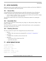
10.3
Directory Structure
The source is released as a zip file. Once unzipped the structure will look like this.
• toplevel
— makefile: This is the location for invoking the ISS, see Section 12, “Example Run.”
• toplevel/obj
— all object files, executables, and cross reference files
• toplevel/src
— either full source files or limited source files
— sportal files and readmes
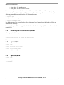
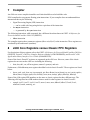
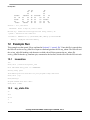
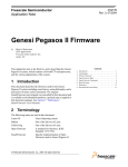
11 edink Splash Screen
I/O system initialized...
Environment is not valid...
Skipping system setup...
Memory Enabled: [ 64MB at CL=3 ]
Caches Enabled: [ none ]
Register Inits: [ 32 GPRs, 155 SPRs ]
Assembler Init: [ 895 opcodes }
Creating edink from DINK32 Code Using the e500 ISS, Rev. 2
Freescale Semiconductor
11
Example Run
######
##
##
#####
##
#####
##
##
##
#######
##
##
##
##
##
##
######
##
##
##
##
##
##
##
#######
##
##
##
##
##
##
##
##
##
##
##
##
##
##
##
######
##
##
##
##
Version : 13.1, GCC Build
Released : Built on Apr 30, 2003 11:28:00
Written by : Freescale’s RISC Applications Group, Austin, TX
System : Instruction Set Simulator
Processor : MPC8540 V1.0 @ (simulated) MHz, Memory @ simulated MHz
Memory : 4GigBytes simulated memory
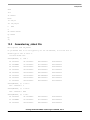
12 Example Run
This example uses the sportal_file as explained in Section 6.3, “sportal_file.” Once this file is sourced then
the ISS will use the src/my_stdin file as input to edink and generate the file my_stdout. The ISS will read
the src/my_stdin file handing each character to edink who will then generate the my_stdout file.
src/my_stdin file has the sq, simulator quit, command as the last line, which will invoke the ISS exit code.
12.1
invocation
iss
e500( idle
)>source src/sportal_file
File indicated entry point of: 0xFFFFFFFC
Setting entry point
4160749439 bytes are available for your program's heap and stack.
e500( idle
)>go
e500(running)>
Program exited with exit code 0
e500( idle
12.2
)>exit
my_stdin File
on
rd r
rm r3
3
rm r8
Creating edink from DINK32 Code Using the e500 ISS, Rev. 2
12
Freescale Semiconductor
Example Run
8080
rd r
as 100000+
here:
lis r20,20
ori r20,r20,20
b
here
x
ds 100000-100020
bp 100008
bp
sq
12.3
Generated my_stdout File
Hello sportal from sim_stdout
Do you desire echo on or off? Typically off for sim terminal, on for sim file io
Please type in "on" or "off" >>
You have chosen "on"
edink[MPC8540] {1} >>rd r
R0 =00000000
R8 =00000000
R16=00000000
R24=00000000
R1 =0008FFE0
R9 =00000000
R17=00000000
R25=00000000
R2 =00000000
R10=00000000
R18=00000000
R26=00000000
R3 =00000000
R11=00000000
R19=00000000
R27=00000000
R4 =00000000
R12=00000000
R20=00000000
R28=00000000
R5 =00000000
R13=00000000
R21=FF0456D8
R29=00000000
R6 =00000000
R14=00000000
R22=00000000
R30=00000000
R7 =00000000
R15=00000000
R23=00000000
R31=00000000
edink[MPC8540] {2} >> rm r3
R03 = 00000000 ? 3
edink[MPC8540] {3} >> rm r8
R08 = 00000000 ? 8080
edink[MPC8540] {4} >> rd r
R0 =00000000
R8 =00008080
R16=00000000
R24=00000000
R1 =0008FFE0
R9 =00000000
R17=00000000
R25=00000000
R2 =00000000
R10=00000000
R18=00000000
R26=00000000
Creating edink from DINK32 Code Using the e500 ISS, Rev. 2
Freescale Semiconductor
13
Documentation Revision History
R3 =00000003
R11=00000000
R19=00000000
R27=00000000
R4 =00000000
R12=00000000
R20=00000000
R28=00000000
R5 =00000000
R13=00000000
R21=FF0456D8
R29=00000000
R6 =00000000
R14=00000000
R22=00000000
R30=00000000
R7 =00000000
R15=00000000
R23=00000000
R31=00000000
edink[MPC8540] {5} >> as 100000+
00100000
00000000
.WORD
0x00000000
here:
00100000
00000000
.WORD
0x00000000
lis r20,20
00100004
00000000
.WORD
0x00000000
ori r20,r20,20
00100008
00000000
.WORD
0x00000000
b
0010000C
00000000
.WORD
0x00000000
x
here:
here
edink[MPC8540] {6} >> ds 100000-10000C
00100000
3E800020
00100004
here:
lis
R20,0x20
62940020
ori
R20,R20,0x20
00100008
48000000
b
0x100008
0010000C
00000000
.WORD
0x00000000
edink[MPC8540] {7} >> bp 100008
Breakpoint at 00100008
edink[MPC8540] {8} >> bp
Breakpoints:
1.
0x00100008
edink[MPC8540] {9} >> sq
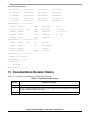
13 Documentation Revision History
Table 13-1 provides a revision history for this application note.
Table 13-1. Document Revision History
Rev. No
Substantive Change(s)
0
Initial release.
1
Changes to comply with edink for the Elysium hardware. Removed section “problems encountered with
simulator”. Added document revision history
2
Updated document to new Freescale template.
Creating edink from DINK32 Code Using the e500 ISS, Rev. 2
14
Freescale Semiconductor
Documentation Revision History
THIS PAGE INTENTIONALLY LEFT BLANK
Creating edink from DINK32 Code Using the e500 ISS, Rev. 2
Freescale Semiconductor
15
How to Reach Us:
Home Page:
www.freescale.com
email:
[email protected]
USA/Europe or Locations Not Listed:
Freescale Semiconductor
Technical Information Center, CH370
1300 N. Alma School Road
Chandler, Arizona 85224
1-800-521-6274
480-768-2130
[email protected]
Information in this document is provided solely to enable system and software
implementers to use Freescale Semiconductor products. There are no express or
implied copyright licenses granted hereunder to design or fabricate any integrated
circuits or integrated circuits based on the information in this document.
Europe, Middle East, and Africa:
Freescale Halbleiter Deutschland GmbH
Technical Information Center
Schatzbogen 7
81829 Muenchen, Germany
+44 1296 380 456 (English)
+46 8 52200080 (English)
+49 89 92103 559 (German)
+33 1 69 35 48 48 (French)
[email protected]
Freescale Semiconductor reserves the right to make changes without further notice to
Japan:
Freescale Semiconductor Japan Ltd.
Headquarters
ARCO Tower 15F
1-8-1, Shimo-Meguro, Meguro-ku
Tokyo 153-0064, Japan
0120 191014
+81 3 5437 9125
[email protected]
parameters, including “Typicals” must be validated for each customer application by
Asia/Pacific:
Freescale Semiconductor Hong Kong Ltd.
Technical Information Center
2 Dai King Street
Tai Po Industrial Estate,
Tai Po, N.T., Hong Kong
+800 2666 8080
[email protected]
unauthorized application, Buyer shall indemnify and hold Freescale Semiconductor
For Literature Requests Only:
Freescale Semiconductor
Literature Distribution Center
P.O. Box 5405
Denver, Colorado 80217
1-800-441-2447
303-675-2140
Fax: 303-675-2150
LDCForFreescaleSemiconductor
@hibbertgroup.com
Freescale™ and the Freescale logo are trademarks of Freescale Semiconductor, Inc.
The Power Architecture and Power.org word marks and the Power and Power.org logos
and related marks are trademarks and service marks licensed by Power.org. All other
product or service names are the property of their respective owners.
Document Number: AN2336
Rev. 2
12/2006
any products herein. Freescale Semiconductor makes no warranty, representation or
guarantee regarding the suitability of its products for any particular purpose, nor does
Freescale Semiconductor assume any liability arising out of the application or use of
any product or circuit, and specifically disclaims any and all liability, including without
limitation consequential or incidental damages. “Typical” parameters which may be
provided in Freescale Semiconductor data sheets and/or specifications can and do
vary in different applications and actual performance may vary over time. All operating
customer’s technical experts. Freescale Semiconductor does not convey any license
under its patent rights nor the rights of others. Freescale Semiconductor products are
not designed, intended, or authorized for use as components in systems intended for
surgical implant into the body, or other applications intended to support or sustain life,
or for any other application in which the failure of the Freescale Semiconductor product
could create a situation where personal injury or death may occur. Should Buyer
purchase or use Freescale Semiconductor products for any such unintended or
and its officers, employees, subsidiaries, affiliates, and distributors harmless against all
claims, costs, damages, and expenses, and reasonable attorney fees arising out of,
directly or indirectly, any claim of personal injury or death associated with such
unintended or unauthorized use, even if such claim alleges that Freescale
Semiconductor was negligent regarding the design or manufacture of the part.
© Freescale Semiconductor, Inc., 2004, 2006.