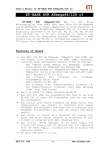
1
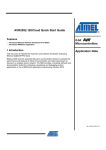
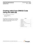
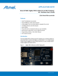
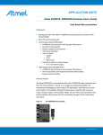
AVR2052: BitCloud Quick Start Guide
Features
• Introduces BitCloud the Software Development Kit (SDK)
• Introduces the WSN Demo application
1 Introduction
8-bit
Microcontrollers
Application Note
This document is intended for engineers and software developers evaluating the
BitCloud ZigBee® PRO stack.
The BitCloud SDK and the supported kits serve as the perfect vehicle to evaluate
the performance and features of Atmel microcontrollers and radio transceivers as
devices in a wireless sensor network. The user can build applications on top of the
ZigBee PRO stack by using its C API.
Rev. 8200B-AVR-02/09
2 References
[1]
AVR®2051: BitCloud Stack Documentation.
[2]
AVR2050: BitCloud User Guide.
[3]
AVR Studio®. User Guide. Available in HTML Help within the product.
[4]
WinAVR User Manual – 20081205
[5]
Using the GNU Compiler Collection
[6]
RZRAVEN Firmware Documentation. (AVR2017: RZRAVEN Firmware)
[7]
AVR2015: RZRAVEN Quick Start Guide
[8]
AT91 USB CDC Driver Implementation. 6269A–ATARM–10-Oct-06
http://www.atmel.com/dyn/resources/prod_documents/doc6269.pdf
[9]
ZigBit Development Kit User’s Guide. Available at
http://www.meshnetics.com/downloads/docs/
[10]
SerialNet AT Command Set Reference Manual. Available at
http://www.meshnetics.com/downloads/docs/
[11]
Serial Bootloader User’s Guide. Available at
http://www.meshnetics.com/downloads/software/
3 Overview
The BitCloud is a full-featured, professional grade embedded software ZigBee stack
from Atmel®. The stack provides a software development platform for reliable,
scalable, and secure wireless applications running on Atmel microcontrollers and
radio transceivers. BitCloud is designed to support a broad ecosystem of userdesigned applications addressing diverse requirements while enabling a full spectrum
of software customization.
The following hardware platforms are supported by the BitCloud SDK.
Table 3-1. Supported hardware platforms
Name in This
Document
Platform
(MCU + RF)
Supported Modules
Supported Evaluation
Kit
Appropriate SDK
ATAVRRZRAVEN
AT90USB1287
+ AT86RF230
N/A
ATAVRRZRAVEN
(consists of
ATAVRRZUSBSTICK
and ATAVRRAVEN
devices)
BitCloud for
ATAVRRZRAVEN
ATmega1284P
+
ATmega3290P
+ AT86RF230
ZigBit
ATmega1281 +
AT86RF230
ATZB-24-B0 (ZigBit);
ATZB-24-A2 (ZigBit A2);
ATZB-A24-UFL (ZigBit Amp)
ATZB-DK-24 (ZDK);
ATZB-DK-A24
(ZDK Amp)
BitCloud for ZDK;
BitCloud for ZDK Amp
ZigBit 900
ATmega1281 +
AT86RF212
ATZB-900-B0 (ZigBit 900)
ATZB-DK-900 (ZDK 900)
BitCloud for ZDK 900
Please note that this document describes the use of BitCloud with the specific
modules and evaluation kits listed in the table above. Operation of BitCloud on
2
AVR2052
8200B-AVR-02/09
AVR2052
supported MCU+RF combinations realized in a custom hardware application is
outside the scope of this document.
The BitCloud stack is fully compliant with ZigBee PRO and ZigBee standards for
wireless sensing and control. It provides an augmented set of APIs which, while
maintaining full compliance with the standard, offer extended functionality designed
with developer's convenience and ease-of-use in mind.
The main structure of the BitCloud stack is presented in Figure 3-1.
Figure 3-1. BitCloud Block Diagram
The topmost of the core stack layers, APS, provides the highest level of networkingrelated API visible to the application. ZDO provides a set of fully compliant ZigBee
Device Object API which enable main network management functionality (start, reset,
formation, join). It also defines ZigBee Device Profile types, device and service
discovery commands implemented by the stack.
The general guidelines to developing applications with BitCloud are given in [2]. The
SDK also includes the WSN Monitor PC application in binary format and WSN Demo
embedded application available in binary format and source code.
The source code for WSN Demo reference can be modified and extended, making it
possible to develop WSN applications for a variety of application scenarios. The
WSNDemo application is described in detail in Section 5.
For ZigBit and ZigBit 900 platforms, the SDK also includes other reference
applications described in Section 6.4.
4 Getting Started
This chapter describes how to quickly get BitCloud running on the selected hardware
platform. The BitCloud SDK is available for several platforms as described in Section
2. Please pick the SDK revision that matches your target platform.
3
8200B-AVR-02/09
The majority of instructions for setting up BitCloud stack and applications depend on
specifics of a particular platform and evaluation kit. To get started, proceed to the
platform-specific sections listed below.
Table 4-1. Hardware-Specific Getting Started Sections
For Platform
Refer to Section
ATAVRRZRAVEN
8.1
ZigBit
9.1
ZigBit 900
9.1
After completing installation, try running WSN Demo application by programming the
devices with ready-to-use images as described in Section 5.2.
Finally, the user is ready to create own custom applications based on the BitCloud C
API. See Section 6 for details.
5 WSNDemo Application
5.1 Overview
The network and RF (radio frequency) performance of the hardware components is
demonstrated with the WSNDemo application which is based on the BitCloud API.
This application consists of the embedded firmware, which supports functions for
coordinator, router and end device, and the GUI visualization application, WSN
Monitor, which is run on the PC. In WSNDemo, the nodes communicate based on a
proprietary messaging protocol.
With the WSNDemo application installed, the boards are organized into a set of
nodes forming a ZigBee PRO network.
In this release of the SDK, for ATAVRRZRAVEN, end devices and routers do not
read the data from the onboard sensors. Instead end devices and routers send zero
values to the network coordinator to emulate sensor data and demonstrate data
transmission. For ZigBit platform, end devices and routers send the actual sensor
readings.
End devices follow a duty cycle (microcontroller and radio transceiver are put to
sleep), waking up occasionally to transmit the data. Those transmitted values are
displayed on WSN Monitor panes as temperature, light and battery level
measurements (0s for ATAVRRZRAVEN). Using the USB connection, the coordinator
transmits the received packets, along with its own sensor data (also 0s for
ATAVRRZRAVEN), to WSN Monitor application.
The WSN Monitor visualizes the network topology by drawing a tree of nodes which
have joined the network. For each of the nodes, the parameters like the node’s
address, its node sensor information and link quality data are displayed.
Measured in dBm, RSSI indicates a link’s current condition. The RSSI resolution is 3
dBm. LQI is another numeric parameter defined within the 0 to 255 range to measure
the link quality. Larger values mean a better link, while values close to zero indicate a
poor connection.
In regard to the WSNDemo, Section 5.3 describes how to setup and use the boards.
The user interface is described in Section 5.5.
4
AVR2052
8200B-AVR-02/09
AVR2052
The application is delivered with source code which demonstrates how to develop a
wireless network application using the BitCloud API and provides a useful template
for common application tasks. Development of custom applications is described in
Section 6.
In the WSNDemo, the number of routers and end devices are limited only by the
network parameters described in Section 6.4. However, for the ATAVRRZRAVEN kit
additional restrictions apply. These are outlined in Table 5-1.
Table 5-1. Allowed board role / device type combinations for WSNDemo on
ATAVRRZRAVEN
Device Type
Allowed Board Role
Comments
Coordinator
RZUSBSTICK
Coordinator needs USB interface to send
data to PC-side WSNMonitor application
Router
AVRRAVEN or RZUSBSTICK
End-Node
AVRRAVEN
End-nodes also demonstrate sleep
capabilities (MCU and RF only)
5.2 Programming the Boards
As a first step, WSNDemo images should be loaded onto the boards. The location of
WSNDemo image files are platform specific and are provided in sections specified in
Table 4-1.
The programming instructions and the sets of pre-built application images depend on
the target platform. The table below provides references to the sections that describe
how to program each target platform and evaluation kit.
Table 5-2. Platform-Specific Programming Sections
For Platform
Refer to Section
ATAVRRZRAVEN
8.2
ZigBit
9.2
ZigBit 900
9.2
Running the WSN Demo requires that every device in the network has a 64-bit unique
MAC address. See the appropriate sections in Table 5-2 for how MAC addresses are
assigned for different types of supported boards. Typically, there is a number of precompiled images provided with the SDK that can be used right away without any
modification.
In case of non-ZigBit platforms, for larger networks, or when re-building the
WSNDemo application, MAC addresses should be assigned manually. The address
for a particular node must be specified in Configuration file when defining the
compilation flags for an application (see Section 6.4), and then the application image
must be built separately for each board.
ZigBit and ZigBit 900 platforms do not require manual assignment of MAC addresses
as the evaluation boards are equipped with a dedicated unique ID chip, which
BitCloud stack uses automatically on start up.
Also note that the default images are configured to use a particular Extended PAN ID
and channel mask. To change those parameters you must also modify the
Configuration file and rebuild the images. All and all, special care must be taken by
5
8200B-AVR-02/09
the user when configuring an application so that each compiled image contains a
unique MAC address and all images share the same Extended PAN ID.
The resulting image files containing the unique MAC addresses (whether the default
provided with the SDK, or rebuilt by the user) can be uploaded to the board using
JTAG or, as an option for ZigBit and ZigBit 900 platform, using the serial bootloader
[11].
5.3 Running WSNDemo
The details of running WSNDemo on different boards are essentially platform specific.
Please refer to an appropriate section listed in the table below to get the detailed
instructions for a particular platform.
Table 5-3. Platform-Specific WSNDemo Sections
For Platform
Refer to Section
ATAVRRZRAVEN
8.4
ZigBit
9.4
ZigBit 900
9.4
5.4 Network Organization
The coordinator organizes the wireless network automatically. Upon starting, every
node informs the network on its role.
If you power on the coordinator, it switches to an active state, even though no child
node is present. This is normal, and it indicates that the coordinator is ready and child
nodes can join the network with the coordinator’s PAN ID. By default, the coordinator
uses Extended PAN ID 0xAAAAAAAAAAAAAAAA, which is recognized by all routers.
The short PAN ID is chosen at random. The Extended PAN ID can be modified by the
user through the application Configuration file (see details in Section 6.4).
Note: If the coordinator is absent or it has not been turned on, the routers will remain
in the network search mode. In this mode, routers scan the channels specified in the
channel mask in search of a network with the specified Extended PAN ID.
By default, the channel mask for all application images provided with SDK contains a
single channel. In rare cases, if the frequency corresponding to the radio channel is
busy, the coordinator node may stay in the network search mode. If this happens, you
should change the application’s channel mask to select another channel by changing
the application’s Configuration file, and recompiling the application.
5.5 WSN Monitor
The WSN Monitor is a PC GUI application for WSNDemo that is used to display WSN
topology and other information about the WSN network. A typical WSN Monitor
screen is shown in the figure below. It contains Topology Pane, Sensor Data Pane,
Node Data Pane and Toolbars.
6
AVR2052
8200B-AVR-02/09
AVR2052
Figure 5-1. WSN Monitor GUI
Topology Pane displays the network topology in real time, which helps the user
monitor the formation and dynamic changes in the network while the nodes join, send
data or leave. Topology Pane updates automatically while the nodes are discovered
and while they join to coordinator. The networking tree is constructed on the basis of
next hop links which are tipped with RSSI and LQI values. Each of the nodes
displayed is depicted by an icon with the node’s address below and sensor readings
to the right.
Node Data Pane displays the data coming from onboard sensor’s of each of the
nodes (see Section 5.5.2). It is presented in graph and table form. Other parameters
can be also observed for each node in table form. Node Data Pane includes a Sensor
Selection combo-box used to switch between sensor types.
Node titles are defined in the .node_names.txt file. By default, it is located in the
following subdirectory:
"C:\Program Files\Atmel\WSNMonitor\resources\configuration\”.
Note: the full path to the file depends on the root directory which has been selected
during installation of the SDK (see Section 4).
.node_names.txt contains a number of strings each of which contains 64-bit MAC
address, followed by “=”, and then the title of each node. It may also contain the
optional header string “-- NodeNames --“. For example, see the figure below.
If the .node_names.txt file is not found or its format is not recognized, the WSN
Monitor designates the title names by default. The .nodeNames.txt file only
7
8200B-AVR-02/09
maintains mapping between the embedded MAC addresses and the user-friendly
names to be displayed in the WSN Monitor window.
Figure 5-2. Example .nodeNames.txt containing node titles
5.5.1 Setting up node timeouts
The Connection/Settings menu of WSN Monitor contains a number of
parameters used to control application behavior. Timeouts are used to tune
visualization of coordinator, routers and end devices as the nodes disappear from the
network each time a connection is lost, power is down, or a reset has occurred. A
node timeout corresponds to the time the WSN Monitor application waits for a packet
from a node before assuming that a node is no longer part of the network. Note that
this value does not correspond to the frequency with which data is transmitted by
each type of device. To get smooth topology visualization, setting timeouts to 3 sec is
recommended for coordinator and router and 30 sec is recommended for end device.
Assuming default application configuration, these timeouts cover 3 periods between
sending a packet so at least 3 packets would need to be lost before a node is
removed from WSN Monitor’s Topology Pane.
8
AVR2052
8200B-AVR-02/09
AVR2052
Figure 5-3. WSNMonitor Connection/Settings menu
5.5.2 Visualization of sensor data
Each of the boards sends temperature/light/battery sensors readings (or emulated
values) to the coordinator, which in turn sends it to the PC. The WSN Monitor
displays the readings from onboard sensors next to a node icon inside Topology
Pane (see Section 5.5).
The user can select any node in Topology Pane to monitor the node’s activity and see
the node data in three different forms:
• Text table
• Chart
• The onboard sensor’s data displayed next to each node in Topology Pane. These
values are also tipped with arrows indicating whether the value increased or
decreased in relation to the previous sample.
Note: a given node is selected when clicked on and a dashed frame is drawn around
it.
The same values are shown on Sensor Data Graph Pane, so the user can observe
how the values change over a period of time.
Sensor Data Graph Pane includes a Sensor Selection combo-box. Use the button on
the Sensor Control Toolbar to display the desired types of sensor data.
9
8200B-AVR-02/09
6 Programming with BitCloud API
6.1 API Overview
The BitCloud internal architecture follows IEEE 802.15.4™, ZigBee-defined
convention of splitting the networking stack into logical layers. Besides the core stack
containing protocol implementation, BitCloud contains additional layers implementing
shared services (e.g. task manager, configuration manager, and power manager) and
hardware abstractions (e.g. hardware abstraction layer (HAL) and board support
package (BSP)). The APIs contributed by these layers are outside the scope of core
stack functionality. However, these essential additions to the set of APIs help reduce
application complexity and simplify the development effort. BitCloud Stack
Documentation [1] provides detailed information on the stack’s C API and its use.
The topmost of the core stack layers, APS, provides the highest level of networkingrelated APIs visible to the application. ZDO provides a set of fully compliant ZigBee
Device Object APIs which enable main network management functionality (start,
reset, formation, join). ZDO also defines ZigBee Device Profile types, device and
service discovery commands implemented by the stack.
There are three service "planes" including: task manager, configuration manager, and
power manager. These services are available to the user application, and may also
be utilized by lower stack layers. Task manager is the stack scheduler which all
multiple internal stack components and the user application to run on the same
microcontroller. The task manager utilizes a proprietary priority queue-based
algorithm specifically tuned for multi-layer stack environment and demands of timecritical network protocols. Power management routines are responsible for gracefully
shutting down all stack components and saving system state when preparing to sleep
and restoring system state when waking up. Configuration manager is used by both
the internal stack components and the user application alike to provide a common
way to store and retrieve network parameters like Extended PAN ID and channel
mask.
The Hardware Abstraction Layer (HAL) includes a complete set of APIs for using onmodule hardware resources (EEPROM, app, sleep, and watchdog timers) as well as
the reference drivers for rapid design-in and smooth integration with a range of
external peripherals (IRQ, TWI, SPI, UART, 1-wire), when supported. Board Support
Package (BSP) includes a complete set of drivers for managing standard peripherals
(sensors, UID chip, sliders, and buttons) placed on development boards such as
those provided with ZigBit and ZigBit 900 evaluation kits.
Please refer to [1] and [2] for a more detailed description of the BitCloud API and its
features.
6.2 Using AVR Programming Tools
Unless explicitly stated otherwise for a particular platform, it is recommended that
Atmel’s AVR Studio is used to develop custom applications based on the BitCloud
API. This Integrated Development Environment (IDE) provides the options for editing
source code, compilation, linking object modules with libraries, debugging and more.
AVR Studio User’s manual [3] provides the detailed information about the IDE.
For AVR-based platforms, AVR Studio can be integrated with WinAVR – a suite of
software development tools for the Atmel AVR microprocessors [4]. WinAVR contains
a set of utilities including AVR GCC compiler, linker, automatic Makefile generator,
system libraries, etc. GCC compiler is designed to be executed on the Windows®
10
AVR2052
8200B-AVR-02/09
AVR2052
platform, and is configured to compile C or C++ source code. For description of GCC
compiler, refer to WinAVR documentation. The user can find command options for
compilation and linking specified in [5].
In AVR Studio, each application has a corresponding project file identified by the .aps
extension. All the necessary information about a project is contained in the project
file, which can be double-clicked to open the application’s project in AVR Studio.
6.3 Reserved Hardware Resources
Hardware resources provided by the supported hardware include microcontroller
peripherals, buses, timers, IRQ lines, I/O registers, etc. Many of these interfaces have
corresponding APIs in hardware abstraction layer (HAL) of the BitCloud stack. When
building custom applications on top of the BitCloud API, the user is encouraged to
use the high-level APIs instead of the low-level register interfaces to ensure that the
resource use does not overlap with that of the stack.
The hardware resources reserved for the internal use by the stack in BitCloud are
listed in platform-specific sections specified in the table below. These resources must
not be accessed by the application code. Please note that the lists of the reserved
hardware resources differ for each device.
Table 6-1. Platform-Specific Reserved Resources Sections
For Platform
Refer to Section
ATAVRRZRAVEN
8.5
ZigBit
9.5
ZigBit 900
9.5
6.4 Sample Applications
For all platforms, the SDK is supplied with WSN Demo sample application provided in
source code. WSN Demo is presented in detail in Section 5. To better understand the
communication between the network nodes and between the coordinator and the PC,
the user can refer to Section 10 and Section 11.
For some platforms additional sample applications are available as indicated in the
table below.
Brief Description
WSNDemo
Featured SDK application demonstrating network
functionality of software and additional network
visualization with WSN Monitor. See section 5.
Blink
Introduces the simplest application that uses
timer and LEDs. When started, the application
makes all the LEDs blink synchronously with a
certain period.
ZigBit and
ZigBit 900
Application
ATAVRRZ
RAVEN
Table 6-2. Sample Applications Availability
X
X
X
11
8200B-AVR-02/09
Lowpower
Show how to collect data from low-power,
sleeping devices employing the simplest power
management strategy.
X
Peer2peer
Shows how to organize the simplest peer-to-peer
link. A simple buffering strategy is employed to
avoid byte-by-byte data transfer.
X
PingPong
Shows how process multiple simultaneous data
transmissions. Each node is waiting for a wireless
message, and then passes it to the next node.
X
ThroughputTest
Measures wireless UART bandwidth of ZigBit and
ZigBit 900 boards.
X
ZigBit and
ZigBit 900
Brief Description
ATAVRRZ
RAVEN
Application
For more details on sample applications available for a specific platform refer to [1].
Once the SDK is installed, the source code for the WSN Demo application can be
found inside the “./Sample Applications/WSNDemo“ subdirectory (see Section
4). For other sample applications (where available), the source code can be found in
“./Sample Applications/<application-name>“ subdirectories.
Network parameters and their default values are defined in Configuration file:
#-----------------------------------------------------------------# Compiler type:
#-----------------------------------------------------------------#COMPILER_TYPE = IAR®
COMPILER_TYPE = GCC
#-----------------------------------------------------------------# Stack parameters being set to Config Server
#-----------------------------------------------------------------CS_CHANNEL_MASK = "(1l<<0x0f)"
# Parameter is used only for RF212
CS_CHANNEL_PAGE = 0
CS_RF_TX_POWER = 3
CS_END_DEVICE_SLEEP_PERIOD = 5000
CS_NEIB_TABLE_SIZE = 8
CS_MAX_CHILDREN_AMOUNT = 7
CS_MAX_CHILDREN_ROUTER_AMOUNT = 2
CS_ROUTE_TABLE_SIZE = 25
CS_ADDRESS_MAP_TABLE_SIZE = 25
CS_ROUTE_DISCOVERY_TABLE_SIZE = 10
CS_APS_DATA_REQ_BUFFER_SIZE = 4
CS_APS_ACK_FRAME_BUFFER_SIZE = 3
CS_DUPLICATE_REJECTION_TABLE_SIZE = 7
CS_NWK_DATA_REQ_BUFFER_SIZE = 4
12
AVR2052
8200B-AVR-02/09
AVR2052
CS_NWK_DATA_IND_BUFFER_SIZE = 4
USE_STATIC_ADDRESSING = 0
# Used only for static addressing
CS_NWK_ADDR = 0x7001
CS_UID =
0x0000000000000001LL
CS_EXT_PANID = 0xAAAAAAAAAAAAAAAALL
APP_DEVICE_TYPE = COORDINATOR
#APP_DEVICE_TYPE = ROUTER
#APP_DEVICE_TYPE = ENDDEVICE
6.4.1 Compiling Applications
The following development environment options are available for each of the
supported platforms.
Table 6-3. Platform-Specific Compilation Options
For Platform
AVR Studio +
WinAVR
ATAVRRZRAVEN
X
ZigBit
X
ZigBit 900
X
In order to compile an application, the following steps should be taken:
1
Command line: Compile application by running make utility. Before running
make, be sure that Configuration file has COMPILER_TYPE variable set to
GCC.
2 IDE: Open the .aps file from the appropriate directory with AVR Studio and
execute “Build/Rebuild All” from the main menu.
As a result, .hex and .srec application images will be generated.
7 Basic Troubleshooting
In case of any operational problem with your system please check the following:
1. Check the power first, and make sure that all of your equipment is properly
connected.
2. Check if your PC conforms to the minimum system requirements (see Section 4).
3. Check if the PC USB or UART interface is working and the correct drivers are
installed (see Section 4).
4. Check hardware kit documentation if you have setup and are using the hardware
in the right way. See Section 4 for specific hardware setup requirements.
5. For ATAVRRZRAVEN, check LCD indication of AVRRAVEN nodes to detect the
cases when they are not responding or behaving unusually.
6. Make sure you have programmed the right images and set the correct Fuses
values (see Section 5.2).
13
8200B-AVR-02/09
Resetting the node may be required.
The table below represents some typical problems that you may encounter while
working with the Development Kit and possible solutions.
Table 7-1. Typical problems and solutions
14
Problem
Solution
For ATAVRRZRAVEN:
The AVRRAVEN board
does not indicate its
activity on LCD.
Make sure that WSNDemo image is loaded. The LCD
controlling logic depends on the application, and may work
differently for the images built by you.
WSN Monitor fails to start.
Make sure Java machine is properly installed on your PC.
See Section 4.
No node is shown on the
Topology Pane in the WSN
Monitor
Check if the WSN Monitor uses the proper COM port and if
not, change it and restart the program.
WSN Monitor shows NO
DATA in the Sensor Data
Graph Pane.
No node is selected. Select the required node by mouseclicking on it.
Node titles displayed on the
Topology Pane do not show
node destinations.
The displayed titles do not necessarily relate to the node
functions but they can be redefined by the user at any time.
These names are stored in the node title file (see Section
5.5) along with MAC addresses mapped to the nodes.
AVR2052
8200B-AVR-02/09
AVR2052
8 Appendix A-1. ATAVRRZRAVEN Specifics
8.1 Getting Started
8.1.1 Required Hardware
Before installing and using the BitCloud SDK make sure that all necessary hardware
is available for the kit you would like to use:
•
One ATAVRRZUSBSTICK
•
Two or more ATAVRRAVEN boards
•
100-mil to 5o mil JTAG adapter
•
JTAG ICE mkII
8.1.2 Hardware Setup
1. Solder the JTAG headers onto the boards as described in [7].
2. Make sure that the boards have fresh batteries.
8.1.3 System Requirements
Before using the SDK, please ensure that the following system requirements are met
by your PC and development environment.
Table 8-1. System requirements for ATAVRRZRAVEN
Parameter
Value
CPU
Intel Pentium III or higher,
800MHz
RAM
128MB
Free space on hard disk
50MB
JTAG emulator
JTAGICE mkII emulator
with cable
Operating system
Windows 2000/XP
Notes:
Required to upload and debug
firmware onto the boards through
JTAG (see Section 5.2).
AVR Studio 4.14 and
(1)
WinAVR 20081205
Required to upload firmware
images through JTAG (see
Section 5.2), and to develop
applications using API (see
Section 6.2)
Java Runtime
Environment (JRE) 5
Update 8, or later
Required to run WSNMonitor
application
IDE
Java Virtual Machine
Note
1. Users are strongly recommended to use the specified version of
WinAVR. Other versions are not supported and may not work.
8.1.4 Installing the SDK
Proceed with the following installation instructions:
1. Download the archive to your PC and unpack it into an empty folder. As a result,
the following SDK folders and files will be created.
15
8200B-AVR-02/09
Table 8-2. The SDK file structure
Directory/File
Description
./Documentation
Documentation on BitCloud software
./Evaluation Tools/WSNDemo
(Embedded)
Ready-to-use image files for evaluating
WSNDemo. Refer to section 5.2 for the
description of the images.:
./Evaluation Tools/WSNDemo (WSN
Monitor)/WSNMonitorSetup.exe
WSN Monitor installer
./BitCloud/Components
Header files for BitCloud Stack
./BitCloud/Components/BSP/
Source, header and library files for BitCloud
BSP
./ BitCloud/Components/BSP/
RAVEN/AT3290P
Source and header files for LCD controller
firmware
./BitCloud/lib
Library files for BitCloud Stack
./Sample Applications/WSNDemo
Source and image files for WSNDemo
application.
./Third Party Software/6119.inf
USB to Serial Converter driver
2. Download and install Java Runtime Environment, if not already installed on your
PC.
The
Java
Runtime
Environment
is
available
from
http://java.sun.com/javase/downloads/index.jsp.
3. Install AVR Studio, if not already installed on your PC. The current version of the
AVR Studio and Service Pack can be freely downloaded from Atmel’s website
(http://www.atmel.com/dyn/products/tools_card.asp?tool_id=2725). Simply launch
the downloaded installer program and follow the setup instructions.
4. Install WinAVR development suite, if not already installed on your PC. The
WinAVR suite can be downloaded from http://sourceforge.net/projects/winavr. To
install WinAVR follow the setup instructions. Be sure to install only the supported
version of WinAVR as specified in Table 8-1.
5. Install USB to Serial Converter driver. To install the driver, please attach the
RZUSBSTICK device to your PC and wait for Windows to request for a specific
driver for the device. If the RZUSBSTICK already has an assigned driver, or
Windows assigned driver to it automatically, go to Start/Control
Panel/System/Hardware/Device Manager, double-click the RZUSBSTICK device
and select “Update Driver…”. Choose the “Install from a list or
specific location” option and point to 6119.inf provided with this SDK.
Please refer to section 4.9.1 of [8] for further details and basic troubleshooting
options.
8.2 Programming the Boards
8.2.1 Setting Parameters
Running any application on top of BitCloud, including WSNDemo, requires that a 64bit unique MAC address is available. At startup, the software loads MAC address
from EEPROM. The node does not join the network unless the address is non-zero
and different from 0xFFFFFFFFFFFFFFFF.
The ready-to-use binary images which come with the SDK (WSNDemoApp_*.hex)
come with different MAC addresses and thus can be used for creating a small
network (no need to program the EEPROM). See Section 8.3 for details.
16
AVR2052
8200B-AVR-02/09
AVR2052
For larger networks or when re-building of an application is involved, MAC addresses
should be programmed manually. The address for a particular node must be specified
in the Configuration file when defining the compilation flags for an application (see
details in Section 6.4), and then the application image must be built separately for
each board.
Also note that the default images are configured to use Extended PAN ID
0xAAAAAAAAAAAAAAAA and channel mask with channel 0x0F enabled. To change
those parameters you must also modify the Configuration file and rebuild the images.
8.2.2 Programming
Refer to AVR Studio documentation for the description of how the images can be
programmed to the boards using JTAG.
For additional details, please refer to “readme.html > RZRAVEN: RZRAVEN
Firmware
Documentation
>
Miscellaneous
information
>
Programming the RZRAVEN Firmware with Programmer/Debugger” section
of [6].
Set the following options in the Fuses tab before uploading the image through JTAG.
Note the values differ for different types of boards.
Table 8-3. Fuse bits setting for AT90USB1287 (RZUSBSTICK)
Option
Value
BODLEVEL
Brown-out detection at VCC=2.4 V
HWBE
Disabled
OCDEN
Disabled
JTAGEN
Enabled
SPIEN
Enabled
WDTON
Disabled
EESAVE
BOOTSZ
Disabled
Boot Flash size=4096 words start address=$F000
BOOTRST
Disabled
CKDIV8
Disabled
CKOUT
EXTENDED
Disabled
Ext. Crystal Osc. 3.0-8.0 MHz; Start-up time: 16K
CK + 65 ms
0xFC
HIGH
0x99
LOW
0xFD
SUT_CKSEL
Table 8-4. Fuse bits setting for ATmega1284p (AVRRAVEN)
Option
Value
BODLEVEL
Brown-out detection at VCC=1.8V
OCDEN
Disabled
JTAGEN
Enabled
SPIEN
Enabled
WDTON
Disabled
EESAVE
Disabled
BOOTSZ
Boot Flash size=512 words start address=$FE00
17
8200B-AVR-02/09
Option
Value
BOOTRST
Disabled
CKDIV8
Enabled
CKOUT
Disabled
SUT_CKSEL
Int. RC Osc.; Start-up time: 6 CK + 65 ms
EXTENDED
0xFE
HIGH
0x9F
LOW
0x62
Table 8-5. Fuse bits setting for ATmega3290p (LCD on AVRRAVEN)
Option
Value
BODLEVEL
Brown-out detection at VCC=1.8V
RSTDISBL
Disabled
OCDEN
Disabled
JTAGEN
Enabled
SPIEN
Enabled
WDTON
Disabled
EESAVE
Disabled
BOOTSZ
Boot Flash size=512 words start address=$3E00
BOOTRST
Disabled
CKDIV8
Enabled
CKOUT
Disabled
SUT_CKSEL
Int. RC Osc.; Start-up time: 6 CK + 65 ms
EXTENDED
0xFD
HIGH
0x9D
LOW
0x62
8.3 Pre-Built Images
The SDK comes with ready-to-use binary images of WSNDemo application
(WSNDemoApp_*.hex). There is a set of images for different roles and with different
MAC addresses and thus can be used for creating a small network (no need to
program the EEPROM):
1. WSNDemoApp_USB_C_1.hex – for RZUSBSTICK (AT90USB1287 controller)
acting as Coordinator
2. WSNDemoApp_USB_R_2.hex – for RZUSBSTICK (AT90USB1287 controller)
acting as Router
3. WSNDemoApp_Raven_R_3.hex
–
for
AVRRAVEN
(ATmega1284p
microcontroller) acting as Router
4. WSNDemoApp_Raven_E_4.hex
–
for
AVRRAVEN
(ATmega1284p
microcontroller) acting as End-Node
5. WSNDemoApp_Raven_3290P_LCD.hex – for AVRRAVEN’s LCD controller
(ATmega3290p)
18
AVR2052
8200B-AVR-02/09
AVR2052
Program these ready-to-use images as defined below:
• On RZUSBSTICK (Coordinator): WSNDemoApp_USB_C_1.hex;
• On AVRRAVEN #1 (Router): WSNDemoApp_Raven_R_3.hex for ATmega1284p
microcontroller and WSNDemoApp_Raven_3290P_LCD.hex for ATmega3290p
LCD controller (the board contains two JTAG headers – refer to [6]);
• AVRRAVEN #2 (End-Node): WSNDemoApp_Raven_E_4.hex for ATmega1284p
microcontroller and WSNDemoApp_Raven_3290P_LCD.hex for ATmega3290p
LCD controller (the board contains two JTAG headers – refer to [6]);
The table below specifies MAC addresses pre-programmed in ready-to-use images:
Table 8-6. ATAVRRZRAVEN MAC addresses
Image Name
MAC address
WSNDemoApp_USB_C_1.hex
0x0000000000000001 (Coordinator)
WSNDemoApp_USB_R_2.hex
0x0000000000000002 (Router)
WSNDemoApp_Raven_R_3.hex
0x0000000000000003 (Router)
WSNDemoApp_Raven_E_4.hex
0x0000000000000004 (End device)
8.4 Running WSN Demo
8.4.1 Starting WSN Demo
To start WSN Demo, do the following:
1.
2.
3.
4.
5.
6.
Setup the hardware as described in Section 8.1.2.
Install BitCloud SDK as described in Section 8.1.4.
Program devices as described in section 8.2.
Plug-in the coordinator USB stick into PC.
Run WSN Monitor (see Section 5.5).
Power ON the rest of the nodes.
8.4.2 Monitoring WSN Demo Activity
Network activity can be monitored in two ways:
• observing the LCD screens of AVRRAVEN devices and color LEDs of
RZUSBSTICK devices (see meaning of LCD information and LEDs described in
the tables below);
• viewing the network information through the WSN Monitor installed on PC.
Table 8-7. LCD indication for AVRRAVEN boards used in WSNDemo
Node State
Visual Information on LCD Screen
Searching for network
“JOINING” string displayed; red LED blinking; “sun”
symbol displayed
Joined to network
“ROUTER” or “ENDDEV” string displayed, depending on
the node role; red LED is on; “sun” symbol displayed
+ receiving data
“RX” indicator visible (please note the limitations due to
LCD refresh rate)
+ sending data
“TX” indicator visible (please note the limitations due to
LCD refresh rate)
19
8200B-AVR-02/09
Node State
Visual Information on LCD Screen
Sleeping (end device only)
Red LED is off; “moon” symbol displayed
Table 8-8. LED indication for the RZUSBSTICK devices used in WSNDemo
Node State
LEDs indication
Powered on
Blue LED is on
Searching for network
Red LED blinking
Joined to network
Red LED is on
+ receiving data
Yellow LED
+ sending data to ZigBee
network (routers and end devices
only)
Green LED
+ sending data to USB
(coordinator only)
Green LED
Sleeping
Not supported for RZUSBSTICK
8.5 Reserved Hardware Resources
Table 8-9. Hardware resources reserved by the stack on RZUSBSTICK devices
Resource
Description
Processor main clock
8MHz oscillator with external quartz
SPI
Radio interface
AT90USB1287 ports: PB0, PB1,
PB2, PB3, PB4, PB5, PB7, PD4
Radio interface
Timer/Counter3
Radio interface
Timer/Counter1 capture input
Radio interface
Timer/Counter1
System timer
Table 8-10. Hardware resources reserved by the stack on AVRRAVEN devices
20
Resource
Description
Processor main clock
4 or 8MHz from internal RC-oscillator or external radio
frequency
SPI
Radio interface
ATmega ports PB0, PB1, PB3,
PB4, PB5, PB6, PB7, PD6
Radio interface
ATmega ports PC6, PC7
Asynchronous timer interface
Timer/Counter2
Asynchronous timer
Timer/Counter3
Radio interface
Timer/Counter1
System timer
Timer1 ICP IRQ
Radio interface
EEPROM
Storage for user settings accessible via Persistent Data
Server
AVR2052
8200B-AVR-02/09
AVR2052
9 Appendix A-2: ZigBit and ZigBit 900 Specifics
9.1 Getting Started
9.1.1 Required Hardware
Before installing and using the BitCloud SDK make sure that all necessary hardware
is available for the kit you would like to use:
• ATZB-DK-24, ATZB-DK-A24, or ATZB-DK-900:
o ATZB-DK-24 contains ATZB-EVB-24-B0, ATZB-EVB-24-SMA, ATZB-EVB24-A2 (MeshBean evaluation board) with mounted ZigBit modules;
o ATZB-DK-A24 contains ATZB-EVB-A24-UFL (MeshBean Amp evaluation
board) with ZigBit Amp modules;
o ATZB-DK-900 contains ATZB-EVB-900-B0 (MeshBean 900 evaluation
board) with ZigBit 900 modules.
• JTAGICE mkII
9.1.2 Hardware Setup
No special pre-usage assembly is required for MeshBean boards supplied with ZigBit
Development Kits.
Please note that the boards can be powered in one of the three ways:
• by a pair of AA-size batteries;
• via the USB port (once connected for data transfer, see also Section 9.1.4);
• via an AC/DC adaptor.
The nominal voltage is 3V for MeshBean and MeshBean 900 boards, 3.3V for
MeshBean Amp. Using AC/DC adaptor automatically disconnects AA batteries. Using
USB port disconnects the AC/DC adaptor.
9.1.3 System Requirements
Before using the SDK, please ensure that the following system requirements are met
by your PC and development environment.
Table 9-1. System requirements for ZigBit and ZigBit 900
Parameter
Value
CPU
Intel Pentium III or higher,
800MHz
RAM
128MB
Free space on hard disk
50MB
JTAG emulator
JTAGICE mkII emulator
with cable
Operating system
Windows 2000/XP
Note
Required to upload and debug
firmware onto the boards through
JTAG (see Section 5.2).
21
8200B-AVR-02/09
Parameter
Value
Note
AVR Studio 4.15 build 623
(1)
and WinAVR 20081205
Required to upload firmware
images through JTAG (see
Section 5.2), and to develop
applications using API (see
Section 6.2)
Java Runtime
Environment (JRE) 5
Update 8, or later
Required to run WSNMonitor
application
IDE
Java Virtual Machine
Notes:
1.
Users are strongly recommended to use the specified version of WinAVR.
Other versions are not supported and may not work.
9.1.4 Installing the SDK
Proceed with the following installation instructions.
1. Download the archive to your PC and unpack it into an empty folder. As a result,
the following SDK folders and files will be created.
Table 9-2. The SDK file structure
Directory/File
Description
./Documentation
Documentation on BitCloud software
./Evaluation Tools/WSNDemo
(Embedded)
Ready-to-use image files for evaluating
WSNDemo. Refer to section 5.2 for the
description of the images.:
./Evaluation Tools/WSNDemo (WSN
Monitor)/WSNMonitorSetup.exe
WSN Monitor installer
./Evaluation Tools/SerialNet
Ready-to-use image files for SerialNet
application. Refer to [9] and [10] for more
information on SerialNet.
./BitCloud/Components
Header files for BitCloud Stack
./BitCloud/Components/BSP/
Source, header and library files for BitCloud
BSP
./BitCloud/lib
Library files for BitCloud Stack
./Sample Applications/WSNDemo
Source and image files for WSNDemo
application.
./Sample Applications/<other
names>
Other sample applications – source and
image files
2. Download and install Java Runtime Environment, if not already installed on your
PC.
The
Java
Runtime
Environment
is
available
from
http://java.sun.com/javase/downloads/index.jsp.
3. Install AVR Studio, if not already installed on your PC. The current version of the
AVR Studio and Service Pack can be freely downloaded from Atmel’s website
(http://www.atmel.com/dyn/products/tools_card.asp?tool_id=2725). Simply launch
the downloaded installer program and follow the setup instructions.
4. Install WinAVR development suite, if not already installed on your PC. The
WinAVR suite can be downloaded from http://sourceforge.net/projects/winavr. To
install WinAVR follow the setup instructions. Be sure to install only the supported
version of WinAVR as specified in Table 9-1.
22
AVR2052
8200B-AVR-02/09
AVR2052
5. The board can be connected to host PC via USB port, using USB 2.0 A/mini-B
cable. USB is a familiar connection option. Furthermore, it provides the
convenient way to link multiple boards to a single PC, and no battery is required
once a board is powered via USB.
6. Alternatively, the board can be connected to host PC via serial port, using a serial
cable. Please note that USB and serial port (RS-232) share the same physical
port on the board. They cannot be used at the same time. Keep in mind that the
connection mode is controlled by setting of jumper on a MeshBean. Refer to
Section 9.3 for the description of connectors and jumpers on MeshBean boards.
7. If you plan to use USB connection, install USB to UART Bridge VCP driver. To
install the driver, please do the following:
a. Download the driver from
https://www.silabs.com/products/mcu/Pages/USBtoUARTBridgeVCPDrivers.
aspx
b. Attach the MeshBean board to the USB port of your PC. Windows should
detect the new hardware. Follow the instructions provided by the driver
installation wizard.
c. Make sure that the driver is installed successfully and the new COM port is
present in the device list. Check that the device is correctly shown in the
Device Manager window as on the figure below:
Figure 9-1. Correctly installed COM port for MeshBean device
23
8200B-AVR-02/09
9.1.5 Selected jumpers on MeshBean boards
This section defines settings for some of the jumpers used on the MeshBean board.
For more information on jumper settings and interface pinouts refer to [9]. Note that
J2 settings differ for ZigBit, ZigBit 900, and ZigBit Amp.
Table 9-3. J2 jumper settings for ZigBit and ZigBit 900: power source
Jumper position
Description
J2 bridges POWER pin
and BAT pin
ZigBit is powered by primary source (battery, USB or AC/DC
adapter).
J2 bridges POWER pin
and DC/DC pin
ZigBit is powered by 3.6 V internal voltage regulator.
Table 9-4. J2 jumper settings for ZigBit Amp: power source
Jumper position
Description
J2 bridges pin 2 and pin
3
ZigBit is powered by USB
J2 bridges pin 2 and
pin 1
ZigBit is powered by external DC source or by batteries if
external DC source is disconnected.
Table 9-5. J3 jumper settings for all types: Serial/USB selection
Jumper position
Description
J3 bridges central pin
and RS-232 pin
The board will use serial port (available in the Expansion slot) for
connection to the host.
J3 bridges central pin
and USB pin
The board will use USB for connection to the host.
Warning: Any other position of jumpers J2 and J3 or their omission may permanently
damage the MeshBean boards.
9.2 Programming the Boards
9.2.1 Setting Parameters
Running any application on top of BitCloud, including WSNDemo, requires that a 64bit unique MAC address is available. The node does not join the network unless the
address is non-zero and different from 0xFFFFFFFFFFFFFFFF.
At startup, the software assigns the MAC address as follows. First, it tries to load
MAC address from EEPROM. If there is 0 or 0xFFFFFFFFFFFFFFFF value in
EEPROM, BitCloud attempts to load MAC address from a dedicated UID chip. If there
is no UID, the node will not be able to join the network.
The ready-to-use binary images which come with the SDK (WSNDemoApp_*.hex)
come with MAC addresses in EEPROM set to 0, thus it is retrieved automatically from
UID, and a single image can be used for programming all nodes in the network –
nodes will have unique addresses as a result.
Also note that the default images are configured to use Extended PAN ID
0xAAAAAAAAAAAAAAAA and channel mask:
• channel 0x0F enabled for ZigBit and ZigBit Amp,
• channel 0x00 (EU) or channel 0x01 (US) (both channel page 0) – for ZigBit 900.
24
AVR2052
8200B-AVR-02/09
AVR2052
To change those parameters you must modify the Configuration file and rebuild the
application images.
9.2.2 Programming
An image file can be uploaded into the boards in one of two ways: using Serial
Bootloader utility, or, in AVR Studio, using JTAG emulator.
Be careful selecting the method of the node programming. Each of MeshBean boards
provided as a part of ZDK come with the bootstrap uploaded onto the ZigBit’s
microcontroller, which is needed to run Serial Bootloader. Using a JTAG to program
the microcontroller will erase the bootstrap, making the loading of application images
with Serial Bootloader inoperable until the bootstrap is restored.
To program a board using Serial Bootloader perform the following steps:
1. Connect MeshBean to the PC via USB or serial port, depending on the
position of jumper J3 (see Section 9.1.5).
2. Run Serial Bootloader. In command line, specify the image file as
WSNDemo.srec, the COM port and the optional command line parameters.
See [11] for details.
3. Press reset button on the board. If a node has been configured as end device
and it is currently controlled by an application, the node should be powered
off before reprogramming.
4. Release reset button on the board. Serial Bootloader expects that the button
will be released within approximately 30 seconds. If this does not happen, the
booting process will terminate.
5. Serial Bootloader indicates the operation progress. Once an upload is
successfully completed, the board would restart automatically. If an upload
fails, Serial Bootloader would indicate the reason. In rare cases, booting
process can fail due to the communication errors between the board and the
PC. If this happened, attempt booting again or try using conventional serial
port, instead of USB. If booting fails, the program written to the board recently
would be corrupted, but the board can be reprogrammed again as the
bootstrap should remain intact.
Refer to AVR Studio documentation for the description of how the images can be
programmed to the boards using JTAG.
Set the following options in the Fuses tab before uploading the image through JTAG.
Table 9-6. Fuse bits setting for ZigBit, ZigBit Amp, ZigBit 900
Option
Value
BODLEVEL
Brown-out detection disabled
OCDEN
Disabled
JTAGEN
Enabled
SPIEN
Enabled
WDTON
Disabled
EESAVE
Disabled
BOOTSZ
Boot Flash size=1024 words start address=$FC00
BOOTRST
Disabled*
If the node is to be programmed with the use of Serial
Bootloader, enable the BOOTRST option.
25
8200B-AVR-02/09
Option
Value
CKDIV8
Enabled
CKOUT
Disabled
SUT_CKSEL
Int. RC Osc.; Start-up time: 6 CK + 65 ms
Make sure the following hex values appear in the bottom part of Fuses tab:
0xFF, 0x9D, 0x62.
If the node is to be programmed with the use of Serial Bootloader, enable additionally
the BOOTRST option. Make sure the following hex value string appears at the bottom
of Fuses tab:
0xFF, 0x9C, 0x62.
By default, each of the boards coming in ZDKs is preprogrammed with this fuse
setting.
9.3 Pre-Built Images
The SDK comes with the following ready-to-use binary images:
• For ZigBit:
o
WSNDemo application: WSNDemoApp.hex, WSNDemoApp.srec.
These images can be programmed to any board (.hex using JTAG,
.srec using Serial Bootloader). MAC address and node role are
defined automatically – see below.
o SerialNet application: sn_stdAll.hex, sn_stdAll.srec. These
images can be programmed to any board (.hex using JTAG, .srec
using Serial Bootloader). MAC address and node role are defined
automatically – see below.
• For ZigBit 900:
o WSNDemo
application:
WSNDemoApp_*.hex,
WSNDemoApp_*.srec. These images can be programmed to any
board (.hex using JTAG, .srec using Serial Bootloader). MAC
address and node role are defined automatically – see below.
WSNDemoApp_US.* are the images with channel 0x01 / channel
page 0 enabled. This channel is unlicensed in Europe. Thus,
WSNDemoApp_EU.* images, with channel 0x00 enabled, are
provided specially for using in Europe.
SerialNet application: sn_stdAll.hex, sn_stdAll.srec. These
images can be programmed to any board (.hex using JTAG, .srec
using Serial Bootloader). MAC address and node role are defined
automatically – see below.
The ready-to-use binary images which come with the SDK come with MAC addresses
in EEPROM set to 0. MAC addresses are thus loaded automatically from a dedicated
unique ID chip, ensuring that unique MAC addresses are assigned to all network
nodes., The node role is determined by setting the DIP switches on the board – see
Section 9.4.2 for details.
o
26
AVR2052
8200B-AVR-02/09
AVR2052
9.4 Running WSNDemo
9.4.1 Starting WSNDemo
To start WSN Demo, do the following:
1.
2.
3.
4.
5.
6.
7.
8.
Setup the hardware as described in Section 9.1.2.
Install BitCloud SDK as described in Section 9.1.4.
Program devices as described in section 9.2.
Configure one single node as a coordinator, and make the others be routers and
end devices (see Section 9.4.2). Any of the boards provided can be configured
with any role.
Connect the coordinator node to the PC, using USB port on the coordinator board
Power on the coordinator node
Run WSN Monitor (see Section 5.5)
Power ON and reset the rest of the nodes.
9.4.2 Node Role Configuration
The role of the node – coordinator, router, or end-device is configured using DIP
switches on MeshBean board.
Table 9-7. DIP switches configurations on MeshBean boards used in WSNDemo
DIP Switches
Selected Role
1
2
3
ON
OFF
OFF
OFF
ON
OFF
Router
OFF
OFF
ON
End-Device
Coordinator
9.4.3 Monitoring WSN Demo Activity
Network activity can be monitored in two ways:
• observing color LEDs of MeshBean boards (see the table below);
• viewing the network information through WSN Monitor installed on PC.
Table 9-8. LED indication for MeshBean boards used in WSNDemo
Node State
LED1 (Red)
LED2 (Yellow)
LED3 (Green)
Searching for network
Blinking
OFF
OFF
Joined to network
ON
+ receiving data
Blinking
+ sending data to UART
(coordinator only)
Sleeping (end device only)
Blinking
OFF
OFF
OFF
27
8200B-AVR-02/09
9.5 Reserved Hardware Resources
Table 9-9. Hardware resources reserved by the stack on ZigBit, ZigBit Amp, and
ZigBit 900
28
Resource
Description
Processor main clock
4 or 8 MHz from internal RC-oscillator or external radio
frequency
SPI
Radio interface
ATmega ports PB0, PB1, PB2,
PB3, PB4, PA7, PE5
Radio interface
ATmega port PC1
Interface for amplifier (if present)
ATmega ports PG3, PG4
Asynchronous timer interface
Timer/Counter 2
Asynchronous timer
Timer/Counter 3
Radio interface
Timer/Counter 4
System timer
External IRQ4
Wake-up on DTR
External IRQ5
Radio interface
EEPROM
Storage for user settings accessible via Persistent Data
Server
AVR2052
8200B-AVR-02/09
AVR2052
10 Appendix B-1: Over-the-Air Protocol
This appendix describes the protocol used by the WSN Demo sample application.
The description includes the format of the messages exchanged over the air between
the connected nodes. The protocol description allows non-standard nodes (e.g. those
using 3rd party sensors not available on the standard evaluation boards and kits) to
transfer sensor readings and have them visualized in the same WSN Monitor
application.
10.1 Message Format
End-devices and routers send messages to the coordinator using the following
format.
Table 10-1. WSNDemo message format
Field Name
Length
Description
Message Type
1 byte
Type of the messages. Must be 0x01 (0x01 is the only
supported message type for the current revision of
WSNDemo)
Node type
1 byte
Type of the sending node:
0 – coordinator
1 – router
2 – end-device
IEEE address
8 bytes
IEEE address of the sending node
Short address
2 bytes
Short address of the sending node
Version
4 bytes
Version of WSNDemo application protocol used by the
sending node. Currently set to 0x01010100.
Channel mask
4 bytes
Channel mask set on the sending node
PANID
2 bytes
PAN ID of the network to which the sending node is
attached
Channel
1 byte
The channel on which the sending node operates
Parent address
2 bytes
Short address of the parent node
LQI
1 byte
LQI observed by the node that sends this message
RSSI
1 byte
RSSI observed by the node that sends this message
<Additional
fields>
<Variable>
Optional additional fields, see description below in section
10.2
10.2 Additional fields
The message may contain zero, one, or more additional fields that follow the
mandatory fixed-width fields described in the table above. The order of the additional
fields is not fixed. The size of the additional fields may vary – each field contains a
sub-field defining its size. Below is the description of the general format of an
additional field.
Table 10-2. Additional field format
Sub-Field Name
Length
Description
29
8200B-AVR-02/09
Sub-Field Name
Length
Description
Field Type
1 byte
Type of the additional field. The possible values are listed
below.
Field Size
1 byte
Size of the Field Data in bytes. Note: this size does not
include the Field Type and Field Size sub-fields
Field Data
<Variable>
The data depend on the Field Type, the size of the data is
provided by the Field Size
The following types of additional fields are defined:
Table 10-3. Additional field types
Field Type
Description
0x01
Sensors data for board type 1. Used for ATAVRRZRAVEN kit boards
and MeshBean boards.
0x20
Node name.
Please note that in the current version of WSN Demo devices send additional fields of
type 0x01 (sensors readings for boards of type 1) only. Unrecognized additional fields
are discarded by WSN Monitor application. The Field Data format for different field
types are described in the following tables.
Table 10-4. Field Data for type 0x01: Sensors data for board type 1
Offset
Length
Data Type
Description
0
4 bytes
Unsigned int
Battery status reading
4
4 bytes
Unsigned int
Temperature sensor reading
8
4 bytes
Unsigned int
Light sensor reading
Table 10-5. Field Data for type 0x20: Node name
Offset
Length
Description
0
<Variable>
Zero-terminated ASCII string
11 Appendix B-2: Serial Protocol
This appendix describes the protocol and message format used over the serial
connection between the network coordinator and the WSN Monitor application
running on the PC. The messages sent on the serial connection are basically the
messages defined in section 8.1 wrapped as defined below:
Table 11-1. Serial message format
30
Offset
Length
Description
0
2 bytes
Start sequence: 0x10 0x02
2
N bytes
Variable-length payload: the message received from endnode or router or generated by the coordinator, in the
format described in section 8
All 0x10 bytes in this payload are duplicated to avoid
confusion with Start sequence or End sequence
N+2
2 bytes
End sequence: 0x10 0x03
N+4
1 byte
Checksum: Sum of the bytes [0..N+3] mod 256
AVR2052
8200B-AVR-02/09
Disclaimer
Headquarters
International
Atmel Corporation
2325 Orchard Parkway
San Jose, CA 95131
USA
Tel: 1(408) 441-0311
Fax: 1(408) 487-2600
Atmel Asia
Unit 1-5 & 16, 19/F
BEA Tower, Millennium City 5
418 Kwun Tong Road
Kwun Tong, Kowloon
Hong Kong
Tel: (852) 2245-6100
Fax: (852) 2722-1369
Atmel Europe
Le Krebs
8, Rue Jean-Pierre Timbaud
BP 309
78054 Saint-Quentin-enYvelines Cedex
France
Tel: (33) 1-30-60-70-00
Fax: (33) 1-30-60-71-11
Atmel Japan
9F, Tonetsu Shinkawa Bldg.
1-24-8 Shinkawa
Chuo-ku, Tokyo 104-0033
Japan
Tel: (81) 3-3523-3551
Fax: (81) 3-3523-7581
Technical Support
[email protected]
Sales Contact
www.atmel.com/contacts
Product Contact
Web Site
http://www.atmel.com/
Literature Request
www.atmel.com/literature
Disclaimer: The information in this document is provided in connection with Atmel products. No license, express or implied, by estoppel or otherwise, to any
intellectual property right is granted by this document or in connection with the sale of Atmel products. EXCEPT AS SET FORTH IN ATMEL’S TERMS AND
CONDITIONS OF SALE LOCATED ON ATMEL’S WEB SITE, ATMEL ASSUMES NO LIABILITY WHATSOEVER AND DISCLAIMS ANY EXPRESS, IMPLIED
OR STATUTORY WARRANTY RELATING TO ITS PRODUCTS INCLUDING, BUT NOT LIMITED TO, THE IMPLIED WARRANTY OF MERCHANTABILITY,
FITNESS FOR A PARTICULAR PURPOSE, OR NON-INFRINGEMENT. IN NO EVENT SHALL ATMEL BE LIABLE FOR ANY DIRECT, INDIRECT,
CONSEQUENTIAL, PUNITIVE, SPECIAL OR INCIDENTAL DAMAGES (INCLUDING, WITHOUT LIMITATION, DAMAGES FOR LOSS OF PROFITS,
BUSINESS INTERRUPTION, OR LOSS OF INFORMATION) ARISING OUT OF THE USE OR INABILITY TO USE THIS DOCUMENT, EVEN IF ATMEL HAS
BEEN ADVISED OF THE POSSIBILITY OF SUCH DAMAGES. Atmel makes no representations or warranties with respect to the accuracy or completeness of the
contents of this document and reserves the right to make changes to specifications and product descriptions at any time without notice. Atmel does not make any
commitment to update the information contained herein. Unless specifically provided otherwise, Atmel products are not suitable for, and shall not be used in,
automotive applications. Atmel’s products are not intended, authorized, or warranted for use as components in applications intended to support or sustain life.
© 2009 Atmel Corporation. All rights reserved. Atmel®, logo and combinations thereof, AVR®, STK®, AVR Studio® and others, are the
registered trademarks or trademarks of Atmel Corporation or its subsidiaries. Windows® and others are registered trademarks or trademarks of
Microsoft Corporation in the US and/or other countries. Other terms and product names may be trademarks of others.
8200B-AVR-02/09