1
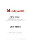
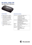
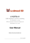
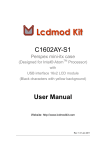
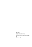
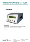
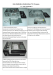
I0AA-M1
Perspex mini-itx case
(Designed for Intel® CoreTM i3/5/7 Processor)
User Manual
Website: http://www.lcdmodkit.com
Rev: 1.01 Apr 2011
CHAPTER 1 INTRODUCTION.................................................................................................. 2
CHAPTER 2 HARDWARE SETUP .................................................................................................... 3
Chapter 1 Introduction
1.1 Package Contents
1.2 Specifiaction
Case Color
Corner Stand
Foot Stand
Dimensions
HDD Bays
Foam Factor
Internal Height
Exhaust Fan
Fan cable
Case
No color crystal clear (Acrylic)
72mm height Silver White (Surface treated sandblasted aluminium)
M5 Screw (Aluminium , 4.5mm height)
190 x 181 x 78mm
(WxLxH, box height only, not included the height of food stand)
[2x] 2.5" HDD (under the motherboard)
mini itx
Total 72mm
Accessories
6cm 6010 Pulse width modulation control
Two way fan out PWM cable
2
Chapter 2 Hardware Setup
2.1 Installing hard disk to the bottom crystal clear plate
2.1.1 Place red fiber liners on mounting holes of hard disk
2.1.2 Place bottom crystal clear plate on the top of hard disk and install screws
(If you only use one hard drive, please cover the exhausted holes of the another drive bay)
2.2 Installing corner stands and nylon studs to the bottom crystal clear plate
3
2.3 Installing rear panel
2.4 Connecting SATA data and power cables
4
2.5 Installing Mainboard and power cable and Wifi connector (if you have)
2.6 Exhausted fan installation (Please remind the arrows sign which marked on the fan, the air
flow arrow point to outward.)
5
2.7 Connecting the 2-way PWM fan cable to CPU fan connector of motherboard
2.8 Connecting the 2-way PWM fan cable (4-cable one for detecting the CPU fan speed) to CPU
fan
6
2.9 Connecting the 2-way PWM fan cable (3-cable one for controlling speed only) to exhaust fan
2.10 Install the power button module (Rotate the screw lightly and mare sure the button can be
pressed and released freely)
2.11 Connecting ON/OFF switch cable
2.11.1 Main board side
7
2.11.2 Switches and indicators side
2.12 Installing front/ side/ crystal clear plat
8
2.11 Installing the top crystal clear plate
9