1
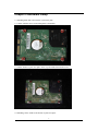
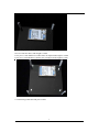
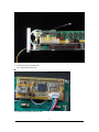
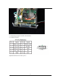
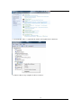
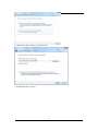
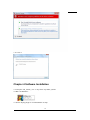
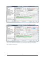
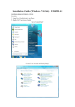
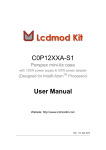
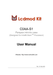
C162AB-S1
Crystal Clear mini-itx case
User Manual
Website: http://www.lcdmodkit.com
Rev: 1.01 Aug 2010
CHAPTER 1 INTRODUCTION.................................................................................................. 2
CHAPTER 2 HARDWARE SETUP .................................................................................................... 3
CHAPTER 3 DRIVER INSTALLATION ............................................................................................. 10
CHAPTER 4 SOFTWARE INSTALLATION ........................................................................................ 14
Chapter 1 Introduction
1.1 Package Contents
1.2 Specifiaction
Case Color
Corner Stand
Foot Stand
Dimensions
HDD Bays
Foam Factor
Internal Height
Case
Crystal Clear (Acrylic)
56mm height Silver White (Surface treated sandblasted aluminium)
M5 Screw (Aluminium , 4.5mm height)
190 x 190 x 60mm
(WxLxH, box height only, not included the height of food stand)
[2x] 2.5" HDD (under the motherboard)
mini itx
Total 56mm (15 - 17mm under main board, 1.5mm main board, 39.5 – 37.5mm above
main board)
Data Transfer
LCD Resolution
LCD color
Screen Size
Work with
Opearting System
USB connection
Front Panel LCD
USB 1.1 compliant
16 Characters x 2 Lines
White characters / blue background
76x26 mm
Lcd Smartie, lcd4linux and LCDProc
Linux, Windows 98, XP, 7 32 & 64 bits
Internal USB connector
2
Chapter 2 Hardware Setup
2.1 Installing hard disk to the bottom crystal clear plate
2.1.1 Place red fiber liners on mounting holes of hard disk
2.1.2 Place bottom crystal clear plate on the top of hard disk and install screws
2.2 Installing corner stands to the bottom crystal clear plate
3
2.3 Installing nylon studs on the bottom crystal clear plate
No use of red fiber liner, studs height is 15mm.
Use 4 pieces 1 mm thickness red fiber liner can adjust studs height to 16mm.
Use 8 pieces 1mm thickness red fiber liner can adjust studs height to 17mm.
2.4 Connecting SATA data and power cables
4
2.5 Installing Mainboard
Make sure no contact between motherboard and harddisk. Use low profile type power supply.
5
2.6 Connecting internal USB cable
2.6.1 USB LCD module side
2.6.2 Main board USB port header side
6
2.7 Installing front crystal clear plate
7
2.8 Connecting front panel switches and indicators
2.8.1 Main board side
(Important! Red color of cable is pin 1)
8
2.8.2 Switches and indicators side
2.9 Installing the top crystal clear plate
9
Chapter 3 Driver Installation
3.1 Power up message
3.2 Error message may be shown on your screen
10
3.3 Copy the driver folder to any driver or desktop of your computer
3.4 Go to “Control Panel”
3.5 Go to “System and Security”
3.6 Go to “Device Manager”
11
3.7 “LCD2USB” with “!”, right click the mourse and “Update Driver Software”
3.8 Choose “Browse my computer for driver software”
12
3.9 Find out the driver folder you copied before
3.10 Install this driver anyway
13
3.11 Close it
Chapter 4 Software Installation
4.1 Unzip the “lcd_smartie_v5.4” to any driver any folder you like.
4.2 Run “LCDSmartie”
4.3 Set the display plugin to “LCD2USB.dll” in setup
14
4.4 Change the LCD size to “2x16” and tune the LCD contrast and brightness of backlight
Note: For more details about LCDSmartie, please go through the official site of LCDSmartie
http://lcdsmartie.sourceforge.net/
15