1
User Manual / Configuration Guide
for the
BASIC IP Pan-Tilt
Control System
Version 1.0 December 2007
Copyright © 2007-2009
J-Systems, Inc.
1 South 678 School Ave.
Lombard, IL 60148
Tel: 630-627-3458
Fax: 630-620-0960
E-Mail: [email protected]
TABLE OF CONTENTS
1.0
Introduction ..........................................................................................
1
1.1
Concept .....................................................................................
1
1.2
Unpacking ..................................................................................
2
1.3
System Components..................................................................
2
1.4
Before You Start ........................................................................
2
Initial Setup ..........................................................................................
3
2.1
Connecting the PT Head ..........................................................
4
2.2
Connecting AC Power ..............................................................
4
3.0
Configuration ........................................................................................
5
4.0
Installation ..........................................................................................
9
4.1
Mounting the Pan-Tilt Head ....................................................
9
4.2
Mounting the Control Enclosure .............................................
10
4.3
Adjusting Pan-Tilt Head Limit Switches ..................................
11
5.0
Setup Interface ....................................................................................
12
6.0
HTML API - Web Page Interface.........................................................
14
7.0
Technical Support ................................................................................
15
8.0
Support Information .............................................................................
15
2.0
8.1
Warranty Policy ..........................................................................
15
8.2
Specifications ............................................................................
16
DISCLAIMER
J-Systems, Inc. makes no warranties, either express or implied, regarding the enclosed
IP Pan-Tilt Controller System, its merchantability or its fitness for any particular purpose.
Further, J-Systems, Inc. assumes no responsibility for any damages, losses or claims
resulting from the use or misuse of this equipment. The extent of any liability is expressly
limited to the original purchase price of the equipment.
1.0 - INTRODUCTION
Congratulations on your purchase of the BASIC IP Pan-Tilt Control System (IP-PT). This
unique harsh environment system was built to the highest quality standards and, with proper
use and installation, will provide many years of service. It is STRONGLY recommend that
you read this manual carefully and completely to fully understand the capabilities of this
system before attempting installation.
CAUTION
The installation and setup of the IP-PT system involves a number of
potentially dangerous operations such as climbing, using man lifts,
working with 120 or 220VAC power, handling heavy items above ground
and working with a device that can be remotely controlled by others.
The installation of the IP-PT system should ONLY be done
by those that are qualified to perform the needed work.
1.1 - Concept
The IP-PT system is an IP based, position control system. It was specifically designed to
allow the positioning of a remote IP camera across IP based networks (wired or wireless
including cellular). Further, all the equipment that makes up this system has been designed
for harsh duty environments (NEMA 4X enclosure, -30C to +70C operation).
The IP-PT system was designed to provide BASIC positional control across any IP based
network. The IP-PT system’s built-in web browser interface is simple allowing for left-right
and up-down control. Custom web pages can easily be designed to display both an IP
camera’s live video as well as graphical controls which allow simple pan and tilt camera
movement. Examples of this type of web page are incluced on the CD.
The IP-PT system provides all the necessary power for the control board and pan-tilt head
using a built in 12VDC, 15W encapsulated power supply that is both TUV approved and CE
marked. As the pan-tilt head operates from 12VDC, an optional 12VDC or 24VDC version
of the IP-PT system is available which uses a 15 watt, 10 to 40VDC DC-DC converter which
provides stable 12VDC for the pan-tilt head. This option is ideal for both mobile and solar
powered applications.
A special high flexibility cable (flexible down to -40C) is provided to connect the pan-tilt head
to the control enclosure. A waterproof RJ45 jack is also provided for connection to a LAN,
wireless radio or cellular router to allow TCP/IP connection to the controller board. The
standard main power connection is through a 1/2” metal liquid tight fitting on the bottom of
the NEMA 4X fiberglass enclosure. The enclosure is furnished with universal stainless steel
mounting brackets.
Finally, the IP-PT system is completely Web browser based allowing easy setup and
configuration. A simple HTML based API is built in which can be incorporated into any web
page to make the controller’s functions appear as if they have been custom designed for
your specific web site.
Page 1
1.2 - Unpacking
The IP-PT system has been carefully packaged to provide protection during shipment. We
suggest that you keep this packaging in the event that factory warranty service is ever
required.
Please inspect and note the condition of the shipping containers before opening them.
Punctures, tears, and crushed ends are indications of abusive treatment by the shipping
company and should be photographed and reported to the carrier in the event any damage
is found inside to file a claim.
1.3 - System Components
Your IP-PT system may have shipped to you in more than one carton depending upon the
items purchased.
Standard Items
Qty 1 - JPTH-13 Pan-Tilt Head
Qty 1 - Fiberglass NEMA 4X Control Enclosure
Qty 1 - 7ft Highly Flexible Interconnect Cable with Military Style Connectors
Qty 2 - Stainless Steel Universal Mounting Brackets for the Control Enclosure
Qty 1 - RJ45 Quick Connect Mating Connector
Qty 1 - User Manual / Configuration Guide CD
Optional Items
Wall Mount with 3” Pedestal for JPTH-13 Pan-Tilt Head
Corner Mount for Wall Mount above
Pole Mount for Wall Mount above
1.4 - Before You Start
A successful installation assumes you have the necessary skills or qualified support
personnel to accomplish the following tasks:
•
•
•
•
Mount the JPTH-13 pan-tilt head and arm to a structure or a mast
Ability to crimp and test RJ45 modular jacks to the end of a CAT5 cable
A method to test CAT5 cables
Ability to wire 120/220VAC power to the IP-PT System control enclosure
(per local electrical code)
• Ability to provide a good earth ground via the 1/2” liquid tight fitting (or ground lug
on the side of the enclosure for DC powered systems)
CAUTION
Always exercise extreme caution when working near power lines or
live circuits to ensure that you, your ladder or other equipment does
NOT come in contact with the power lines. Fatal shocks can occur.
Page 2
2.0 - INITIAL SETUP
Before mounting all your equipment, it is highly recommended that the entire system be setup
and tested completely before pieces of equipment are mounted in difficult to reach locations.
This initial setup and test step will help to ensure a smooth, trouble free installation.
CAUTION
Always exercise extreme caution when working near power lines or
live circuits to ensure that you, your ladder or other equipment does
NOT come in contact with these power lines. Fatal shocks can occur.
If you are not qualified to install the wiring for this unit, please secure
qualified help.
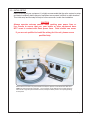
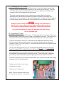
Shown above is the JPTH-13 pan-titl head to the left, the special 7 foot interconnect cable and
NEMA 4X control enclosure to the right . The connectors on the bottom of the control enclosure
are from left to right the pan-titl head connector, waterproof RJ45 jack and 1/2” liquid tight fitting
for AC power.
Page 3
2.1 Connecting the Pan-Tilt Head
Once all of the parts have been identified proceed to connect the supplied special (high
flexibility) cable to the Military style connector on the rear of the pan-tilt head. The other
end of the cable connects to the pan-tilt control enclosure Make sure the Military style
connector shell is fully engaged and locked in place.
This cable is specially designed to be utilized where constant flexing is required.
Additionally, the cable has been selected to maintain its flexibility at extremely cold
temperatures. Do not replace this cable with ordinary cable. If longer sections of cable are
required, please consult the factory for pricing and delivery (the maximum length is 20ft).
CAUTION
Always exercise extreme caution when working near power lines or
live circuits to ensure that you, your ladder or other equipment does
NOT come in contact with these power lines. Fatal shocks can occur.
If you are not qualified to install the wiring for this unit, please
secure qualified help.
2.2 Connecting AC Power
The PTZ controller is supplied with a metal, 1/2” liquid tight fitting. A special grounding ring
has been attached to this fitting on the inside of the fiberglass enclosure. This ground ring is
connected to the back panel and provides the necessary ground for the entire system.
AC power should be run to the IP-PT controller from an appropriate disconnect which
includes a ground fault interrupt function. Local electrical codes should be followed for
outdoor AC wiring. The cover of the IP-PT control enclosure will have to be opened to make
all internal connections.
The AC power fitting provided is for 1/2” liquid tight flexible steel conduit; DO NOT USE
PLASTIC LIQUID TIGHT CONDUIT WHICH HAS NO STEEL GROUNDING ELEMENT.
Proper grounding of the liquid tight flexible steel conduit at the power source must be
accomplished in accordance with local electrical codes. Failure to provide an adequate
ground may result in diminished surge and lighting protection for the PTZ controller.
AC power is brought to the enclosure and terminated in the 3-position terminal block directly
adjacent to the 1/2” liquid tight fitting.
The Black wire is Phase A or the hot leg
The White wire is Neutral
The Green wire is earth ground
NOTE: 10-40VDC powered versions of the
IP-PT system are available - consult factory.
Page 4
3.0 - CONFIGURATION
The following paragraphs will lead you through the setup and configuration of the IP-PT
control system.
3.1 - Install, Setup and Testing
The following sections will cover initial configuration of the controller’s software and
testing. It is recommended that all this configuration be done BEFORE the PT head
and enclosure are mounted outside.
3.1.1 - Initial Power Up and Testing
At this point, the following items should be connected:
• The pan-tilt head should be connected to the IP-PT control enclosure with the special 7ft cable. It would be beneficial to secure the pan-tilt head to the mount it will be ultimately
attached to. This will allow the head to be fully operational during initial setup testing.
• Connect a CAT5 cable to the RJ45 jack on the bottom of the IP-PT control enclosure. The
other end goes to your computer.
•AC power should also now be applied.
Here are the steps you will follow to gain access to the IP-PT controller:
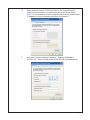
1.
Set your computer’s network adapter IP address to 192.168.1.100 . To
accomplish this in Windows XP or 2000, click on Start, Settings then
Cntrol Panel. Once inside Control Panel double click on the Network
Connections icon as shown to the left.
2.
Once you have clicked on Network Connections, you will see the
icon to the left.
3.
Double click on the Local Area Connection icon; you will see the following
screen.
Page 5
4.
Select Internet Protocol (TCP/IP) and click on the Properties button.
Once you have done this, you will see the next screen shown below.
NOTE: if your computer has been configured with manually entered static
IP address, be sure to document this before you change it.
5.
Now select “Use the following IP address”. Enter an IP address of
192.168.1.10 . Enter a Subnet mask of 255.255.255.0 as shown below.
Page 6
6.
Click OK on this screen and then Close on the next screen.
Your computer is now on the same network as the IP-PT controller’s default
network settings which will allow you to access the IP-PT controller’s
configuration web pages. To do this, open the IE browser and type in the IP
address of 192.168.1.2 and depress Enter. The following screen will appear.
NOTE: All center
indicators will
show “Stopped”
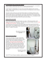
NOTE: The PT Head is shipped in its electrical center postion
for both Pan and Tilt. If you Pan-Right twice during testing, be
sure to Pan-Left twice to re-center the head. The same applies
for Tilt.
At this point, you should be able to use your computer’s mouse and click on anyone of the
“GO” buttons to make the pan-tilt head move.
You will now want to set the IP address of the IP-PTZ controller to your local area network so
you can set your computer’s network adapter back to where it was originally. Enter the following URL into your browser http://192.168.1.2/setup.html and depress ENTER.
Page 7
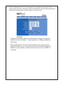
Click the “Network” tab. You will be prompted for a UserName and Password. This
system does not accept a Username so tab over that field and enter the default password of
“password”.The following screen should apear in a second or two.
Change the IP Address, Netmask and Gateway to match your local area
network and click on “Submit”. Leave Speed set to 10Mbps and Mode to
Half Duplex.
After completing this, reset your computer back to your original network
settings and make sure you can still control the PT head by entering its IP
address into your browser to obtain the screen shown on Pg 7 “BASIC IP
Controller”.
Page 8
4.0 - INSTALLATION
At this point, all the hardware should have been tested and proved to be functional.
IMPORTANT - Prior to final installation, you should learn how to adjust the PT head mechanical
limit switches while the PT head is within reach. Final adjustments can of course be done after
the PT head is mounted. Please refer to Para 4.3 before mounting the PT head.
Mount your camera enclosure to the top of the PT Head .
4.1 Mounting the Pan-Tilt Head
The unit has a base which requires 3 x 1/4-20 bolts and washers (supplied) in a 120 degree
bolt-hole pattern. When mounting the head, please remember that a fully loaded pan-tilt
camera enclosure assembly may weigh considerably more than 13 lbs.
The pan-tilt head assembly is electrically and mechanically centered before being shipped
and the connector is located at what we define to be the rear of the pan-tilt head.
Substantial mounting brackets (strong and rigid) will be required to handle this mechanical load
and allow for adverse weather conditions. Bad weather can result in ice and snow build up as
well as high wind loading. Consult the factory if you are unsure as to what type of bracket to
use or to purchase factory available brackets
Stability and rigidness are important as the pan-tilt head with camera and enclosure exerts
inertia when it starts and stops. If the mounting mechanism is not rigid enough, some back and
forth motion may be seen when the head starts and stops.
Once the camera location has been determined, the mounting bracket should be attached
to the mounting surface with suitable heavy duty hardware to assure a safe and secure
installation. Make sure the mounting surface is in good condition; crumbling bricks or cracked
concrete are not to be used.
The camera enclosure must also be given sufficient clearance to ensure that it does not hit
any obstructions when rotated. The motor and gearbox assemblies of the pan-tilt head are
designed to be “stalled” but continuous abuse will cause damage which is not covered under
the warranty.
The pan-tilt head and camera enclosure are very heavy and difficult to hold in one hand. This
equipment should be secured by a safety line to prevent it from falling on someone below if
dropped by the installer.
Also, once operational, this equipment is subject to remote control and may be operated at any
time while you are working on it. Persons working on this equipment should take appropriate
precautions to ensure that any unexpected movement does not occur as this could lead to
finger / hand injury or startle you causing you to fall or slip.
Always leave the power off to the control system and make sure someone is at the control who
will make certain it is not activated without your express knowledge.
A pair of wireless radios are beneficial during installation and / or maintenance so the installer
and the operator can communicate directly.
Page 9
4.2 Mounting the Control Enclosure
The control enclosure has been supplied with rugged, stainless steel mounting brackets. These brackets can be used to mount the control enclosure to a flat wall, a small
mast or larger pole such as a wooden telephone pole or metal light pole.
The brackets accept lag screws or bolts, stainless steel band clamps / straps and
U-bolts. None of this hardware has been supplied as each installation’s mounting
requirements are different.
CAUTION
Always exercise extreme caution when working near power lines or
live circuits to ensure that you, your ladder or other equipment does
NOT come in contact with these power lines. Fatal shocks can occur.
If you are not qualified to install the wiring for this unit, please
secure qualified help.
AC power should be connected as described in Para 2.2 . Again, only liquid tight conduit that supplies an earth ground should be used.
If you have purchased a DC powered system, then a 1/2” plastic bulkhead fitting will be
supplied which can replace the 1/2”metal liquid tight fitting if you like. Also, your enclosure will have a small copper ground lug on the side of the enclosure. This ground lug
MUST be tied to earth ground following NEC code.
You have also been supplied with the mating half of the water proof RJ45 connector.
Follow the supplied directions for inserting your CAT5 cable into this connector.
Page 10
4.3 Adjusting the Pan-Tilt Head Limit Switches
Once the system is operational and the pan-tilt head can be panned and tilted, it is important to
set the mechanical limit switches that control he absolute pan and tilt limits.
For the purposes of identification, the rear of the pan-tilt head is defined as the connector
location. When viewed from the top, clockwise movement is Pan-Right and counter-clockwise
movement is Pan-Left.
The head contains internal pan and tilt limit switched that are controlled by shaft mounted
actuators (2-per shaft). As the head rotates, one actuator trips an externally mounted switch
level arm which causes the pan-tilt head to stop moving in that direction. This system provides
an accurate and simple method of applying pan and tilt limit stops. It is not necessary to power
down or gain access to the inside of the unit to set the limit switches.
Setting the Pan Limit Switch
Drive the pan-tilt head to the left hand position you require. Slide the top actuator until it
engages and trips the switch lever arm. This is best done using a flat blade screwdriver (keep
your fingers out of this area). This limit is now set.
In a similar manner, drive the unit to the extreme right hand position required and slide the
bottom actuator until it engages and trips the switch lever arm. This limit is now set. Drive the
pan-tilt unit to the extreme limits of travel in both directions and check operation for the limit
switches. Re-adjust if necessary.
Photo shows two limit switch
actuators mounted on the
pan shaft.
Setting the Tilt Limit Switch
Drive the pan-tilt head to the upper most position
required (camera would be pointed upward). Slide
the rear actuator until it engages and trips the switch
lever arm. This is best done using a flat blade
screwdriver (keep your fingers out of this area). This
limit is now set. Drive the unit to the lowest point
required (camera pointed downward) and slide the
front actuator until it engages and trips the switch
lever arm. This limit is now set. Drive the pan-tilt unit
to the extreme limits of travel in both directions and
check operation for the limit switches. Re-adjust if
necessary.
Photo shows tilt actuator
tripping the switch lever
arm.
The IP-PT Control System installation and test should now be complete.
Page 11
5.0 - SETUP INTERFACE
If changes are requred to the BASIC IP PT control’s default setting, they can be made by
accessing the built in web intreface of the control. This is accomplished by entering the IP address of the control as follows:
http://192.168.1.2/setup.html
Note:
the controls IP address may have been
changed during Configuration.
Once entered, the following screen will appear:
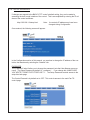
In the Configuratino section of this manual, you saw how to change the IP address of the controller; that was done by selecting the “Network” tab.
PASSWORD
The “Password” tab will allow you to change the password (note that User Names are never
used). The Setup Password by default is “ password “. If you change this, MAKE SURE
YOU WRITE IT DONE FOR FUTURE USE ! ! ! The Setup Password controls access to the
setup.html web page.
The Control Pasword is by default set to OFF. This controls access to the main Pan Tilt
control page.
Page 12
RELAY 1
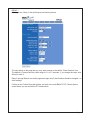
Clicking on the “Relay 1” tab will bring up the following screen:
The only setting on this page that you may want to adjust is the default “Pulse Duration” time.
The default is 1 second and the useful range is 0.1 to 1.5 seconds. If you change the value, click
Submit to save it.
Relay 2 through Relay 4 are similar pages and again only Pulse Duration should be changed - no
other settings.
Clicking on the Control Page tab will take you back to the main BASIC IP PT Control System
screen where you can control the PT Head position.
Page 13
6.0 HTML API - WEB PAGE INTERFACE
Designing custom web pages is very simple assuming you have a basic knowledge of HTML programming.
Please refer to the BASIC IP PT Control System API file located on the included CD.
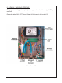
Internal Layout View
Page 14
7.0 TECHNICAL SUPPORT
Technical support is available for no charge during normal business hours.
Business Hours:
Monday - Friday 9:00AM to 4:00PM CST
Contact Information:
Tele:
630-627-3458
Fax:
630-620-0960
E-Mail: [email protected]
Technical support will not be able to help you design custom web pages. These are all
questions best handled by a qualified web programmer.
8.0 SUPPORT INFORMATION
8.1 Warranty Policy
The PTZ Controller carries a 2-year manufacturer’s warranty. This warranty applies to
failure of the product under normal operating conditions. Situations that are not covered by
this warranty include, but are not limited to the following stresses:
• Lightning Strikes
• Repeated Mechanical Stalling of the Head
• Damage Due to Bullets or Other Projectiles
• Cable Damage Due to Animals
• Encasement in Ice
• Applied Voltage Greater Than 264VAC
• Overloading the PTZ Head
• Attempted Repair By An Unauthorized Individual
Any other damage that in J-Systems, Inc.’s opinion have been caused as a result of
abnormal or abusive use will also void the warranty.
Page 15
To return a unit for repair, an RMA (Return Material Authorization) must be obtained prior to
sending the unit back. Units received without a prior RMA being issued will be returned to
the sender unopened.
When returning a unit for warranty or out of warranty repair, the cost of shipping back to the
factory will be borne by the customer. Warranty repaired items will be returned to the customer postage free.
Call 630-627-3458 during normal business hours to obtain an RMA.
8.2 Specifications
The following are general specifications for the IP-PT Control System. These specifications
are subject to change at any time. Detailed specifications are found on the IP-PT Control
System literature piece located on the CD.
Pan-Tilt Head
Height:
5.800 in
Connector:
Nickel Plated MIL-C-26482 14-15
Width:
6.210 in
Speed:
Pan = 28 Deg/Sec.
Depth:
5.08 in with connector
Materials:
Tilt = 8 Deg/Sec.
Machined Alu w/ Stainless Fasteners
Capacity:
13 lbs or less
Anodized Alu Mounting Ring
Rotation Limits:
Pan = 0 to 350 Deg
Polymer Bearings for Quiet Operation
Tilt = -90 Deg Down to +30 Deg Up
Ball Bearings on Major Axes
Color:
Light Grey similar to RAL 9018
Paint:
Powder Coat
Backlash:
< 0.15 Deg
Mounting Plate:
Width = 5.820 in
Maintenance:
None Required
Depth = 4.730 in
Operating Temp:
-30C to +70C
Slots = 1/4 in Hardware or Smaller
No Heating or Cooling Required
Weight:
5 lbs
Braking:
Regenerative
Voltage:
12VDC +/- 5%
Weatherproof:
IP68
Power:
Less than 1.5 W per Axis
Warranty:
2-Years
BASIC IP Controller
Height:
9.500 in
Width:
7.2500 in
Depth:
5.000 in
Materials:
Fiberglass Enclosure - NEMA 4X
Stainless Steel Mounting Brackets
Connectors:
Nickel Plated MIL-C-26482 14-15
Waterproof RJ-45
1/2” Liquid Tight Conduit Fitting
Color:
Light Gray - RAL 7036
Weight:
3 lbs
Voltage:
110/220 VAC, 50-60 Hz (TUV & CE)
Power:
1.5 Watts Max
Operating Temp:
-30C to +70C
Warranty:
2-Years
Page 16