1
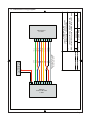
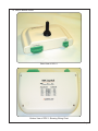
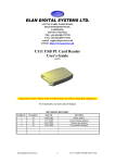
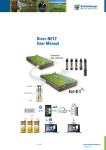
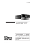
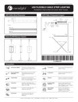
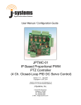
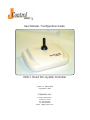
TM User Manual / Configuration Guide DDC-1 Direct DC Joystick Controller Version 1.0 March 2009 Copyright © 2009 J-Systems, Inc. 1 South 678 School Ave. Lombard, IL 60148 Tel: 630-627-3458 Fax: 630-620-0960 E-Mail: [email protected] TABLE OF CONTENTS 1.0 Introduction ........................................................................................ 1 1.1 Concept ..................................................................................... 1 1.2 What’s Required ........................................................................ 1 1.3 Interconnect Wiring Diagram ..................................................... 2 1.4 Rear & Bottom Photos ............................................................... 3 2.0 Operation .......................................................................................... 4 3.0 Technical Support .............................................................................. 5 4.0 Support Information ........................................................................... 5 4.1 Warranty Policy ......................................................................... 5 4.2 Specifications ............................................................................ 6 DISCLAIMER J-Systems, Inc. makes no warranties, either express or implied, regarding the enclosed DDC-1 Direct DC Joystick, its merchantability or its fitness for any particular purpose. Further, J-Systems, Inc. assumes no responsibility for any damages, losses or claims resulting from the use or misuse of this equipment. The extent of any liability is expressly limited to the original purchase price of the equipment. 1.0 - INTRODUCTION Congratulations on your purchase of the DDC-1 Direct DC Joystick controller. This product incorporates a uniquely designed electro-mechanical joystick mounted in a rugged non-metalic enclosure suitable for mobile or fixed control of a JPTH-13 Pan-Tilt Head. 1.1 - Concept This product has been carefully designed and manufactured for the intended purpose of manually controlling a JPTH-13 Pan-Tilt Head. The DDC-1 allows pan, tilt, and diagonal movements of the JPTH-13 provided the joystick is moved away from its center-off position. The DDC-1 will operate using either a 12VDC or 24VDC power supply depending upon the operating voltage of the JPTH-13. There are no electronics or serviceable parts inside the DDC-1. Two locking, pluggable, terminal blocks are provided on the rear of the DDC-1; a 2 position terminal block for power and an 8 position terminal block to allow control of the pan-tilt positioner. While there is no limit to the length of cable between the JPTH-13 and the DDC-1 controller, using more than 50 feet of 18 or 20AWG multi-conductor cable may require the use of a higher voltage power supply to compensate for the voltage drop across the cable. As the voltage is decreased at the pan-tilt head, the DC motors inside the head will run slower and slower. 1.2 - Required Items and Cable Assembly If you did not purchase a pre-made, high flexibility cable assembly from J-Systems, you will need to fabricate a cable assembly of the proper length for your application. We recommend using an 8-conductor, stranded (18 or 20AWG) shielded cable that can withstand flexing in cold temperatures without fracturing. Follow the wiring diagram, shown on the next page, terminate each end of the cable. The mating Amphenol connector for the pan-tilt head is supplied with the pan-tilt head. The Phoenix Contact pluggable headers for the DDC-1 are supplied with the joystick. You will also need a DC power supply capable of supplying 1 Amp at the voltage required for the pan-tilt head (typically 12VDC). Page 1 1.3 Interconnect Wiring Diagram Page 2 1.4 Rear & Bottom Views Rear View of DDC-1 Bottom View of DDC-1 Showing Wiring Chart Page 3 2.0 - OPERATION Operation of the DDC-1 with a JPTH-13 Pan-Tilt Head is very straight forward. Tip: Testing should be completed on the bench before the Pan-Tilt Head is mounted in its final location and the cable run completed. Once the interconnect cable is attached to the Pan-Tilt Head and to the DDC-1, it is now time to connect your power supply. Tip: For a 20AWG cable, you might expect to loose 0.250 VDC per 25 ft of cable (less for 18AWG wire). This will result in a slight reduction in pan and tilt motor speeds. If you have an adjustable power source, you can of course always increase the voltage slightly to compensate for the voltage drop across the cable length. Obviously the longer the cable, the greater the voltage drop will become. CAUTION Be sure to set the mechanical limits on the outside of the Pan-Tilt Head to prevent the unit from causing damage to itself when the joystick is operated. Please refer to the JPTH-13 PT Head User Manual for these adjustment. Please be careful not to pinch your fingers in the Pan-Tilt Head when it is moving. Once power has been applied, you should be able to move the Pan-Tilt Head using the DDC-1 joystick. The motion of the Pan-Tilt Head is that which would be seen if a camera were mounted on top of the unit (the connector on the Pan-Tilt Head is at the rear of the camera). Moving the joystick to the right should cause the Pan-Tilt Head to pan to the right. In a similar manner, the pan left, tilt up and tilt down motions should all work. When the joystick is moved in a diagonal direction between tilt and pan, both the pan and tilt motors will actuate causing the unit to move in a diagonal direction. At this time, if everything is working as expected, disconnect your test setup and mount the Pan-Tilt Head in it final location and make your final cable run for a permanent installation. Tip: When using a shielded cable, the shield is only connected at one end of the cable; the Pan-Tilt end. Pre-made cables from J-Systems also break out the drain wire at the joystick end in the event you wish to attach a ground at this point.. It is good practice to ground the Pan-Tilt Head and its related metal mounting arm / adapter etc using an appropriately sized grounding wire that meets local electrical code. Page 4 3.0 TECHNICAL SUPPORT Technical support is available for no charge during normal business hours. Business Hours: Monday - Friday 9:00AM to 4:00PM CST Contact Information: Tele: 630-627-3458 Fax: 630-620-0960 E-Mail: [email protected] 4.0 SUPPORT INFORMATION 4.1 Warranty Policy The DDC-1 carries a 1-year manufacturer’s warranty. This warranty applies to failure of the product under normal operating conditions. Situations that are not covered by this warranty include, but are not limited to the following stresses and or misuses: • Lightning Strikes • Attempted Repair By An Unauthorized Individual • Running Excessive Current Through the DDC-1 Any other damage that in J-Systems, Inc.’s opinion have been caused as a result of abnormal or abusive use will also void the warranty. To return a unit for repair, an RMA (Return Material Authorization) must be obtained prior to sending the unit back. Units received without a prior RMA being issued will be returned to the sender unopened. When returning a unit for warranty or out of warranty repair, the cost of shipping back to the factory will be borne by the customer. Warranty repaired items will be returned to the customer postage free. Page 5 4.2 Specifications The following are the specifications that apply to the DDC-1. These specifications are subject to change at any time. Joystick: Electro-mechanical Current Limit: 6 Amp Peak motor current Functions: Provides Pan, Tilt, and Diagonal Movements Warranty: 1-year Operating Voltage: 0-28VDC Operating Temperature -30 to +60C Enclosure: ABS Polylac PA-765 Designed for indoor or in-vehicle use UL Flame Rating - 94-VO at 0.59” wall 94-5VA at 0.98” wall UL file Number - E56070 Size: 5” x 7.5” x 4.125” Weight: 0.6 Lbs Terminal Blocks: 2 Position Power Connector Phoenix Contact P/N1827703 8 Position Pan-Tilt Connector Phoenix Contact P/N 1827761 Have a Different Head or Want to Use 24VAC Power The DDC-1 Joystick Controller has been designed to work specifically with the JPTH-13 PT Head running on 12VDC or 24VDC ONLY. In the event that you wish to use a different PT head other than the JPTH-13 from J-Systems, Inc. or have a PT head with 24VAC motors, please consult the factory as a special unit will need to be fabricated for you. Please be prepared to send us a schematic of your PT head, Peak current remains at 6 Amps. Page 6