1
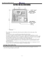
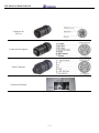
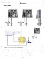
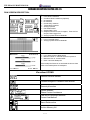
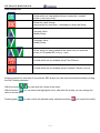
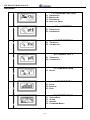
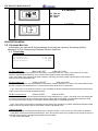
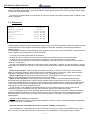
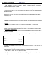
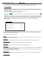
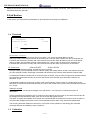
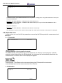
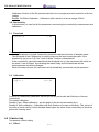
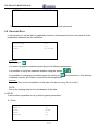
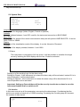
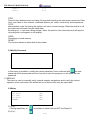
TELEPOOL PROFESSIONAL
TECHNICAL BOOK
( INSTALLATION,SET UP,MAINTENANCE )
TELEPOOL
Professional
ver b_05 del 03/2008
Telepool ver 2.5
Via S. Allende ,9 - 41051 Castelnuovo R.(MO) - Italy
Tel 0039 059 537765
fax 0039 059 5332058
info @ engineeringcorporation.it
-
www.engineeringcorporation.it
Azienda Certificata UN EN ISO 9001
1 / 32
-
CERT. N° 4247
TELEPOOL PROFESSIONAL
GENERAL CLAUSES………………………………………………………………………………- 3 GENERALITY……………………………………………………………………………………… - 4 CONVENTIONS ……………………………………………………………………………………..- 5 SAFETY……………………………………………………………………………………………….- 6 RECYCLING…………………………………………………………………………………………. -8 DECLARATION CE…………………………………………………………………………………- 9 MANUAL OF INSTALLATION……………………………………………………………………- 10 CHARACTERISTICS TOOL………………………………………………………………………- 13 CHARACTERISTICS TECHNICAL MEASURES……………………………………………... - 13 CHARACTERISTICS HARDWARE…………………………………………………………….. - 14 CHARACTERISTICS SOFTWARE……………………………………………………………... - 15 DESCRIPTION SOFTWARE TELEPOOL VER. 2_3…………………………………………. - 16 DESCRIPTION RUNSCREEN:……….…………………………………………………………. - 16 FUNCTION FEELS:……………………………………………………………………………….. - 17 MAIN MENÙ:……...……………………………………………………………………………….. - 18 DESCRIPTION MENÙ:…………………………………………………………………………… - 19 1.0 SECTION CHLORINE………………………………………………………………………... - 19 1.1 THRESHOLDS………………………………………………………………………………… - 19 1.2 BREAKPOINT…………………………………………………………………………………. - 20 1.3 CALIBRATION….……………………………………………………………………………. - 23 1.4 SETUP ANALISI……………………………………………………………..………………. - 23 2.0 SECTION PH…………………………………………………………………………………. - 24 2.1 THRESHOLD…………………………………………………………………………………. - 24 3.0 SECTION REDOX……………………………………………………………………………. - 25 3.1 THRESHOLD…………………………………………………………………………………. - 25 3.2 CALIBRATION…….…………………………………………………………………………. - 25 4.0 CONDUCTIBILITIES…………………………………………………………………………. - 25 4.1 THRESHOLD…………………………………………………………………………………. - 25 4.2 CALIBRATION……….………………………………………………………………………. - 26 5.0 TEMPERATURE……………………………………………………………...………………. - 26 5.1 OFFSETS…………………………………………………………………………...…………. - 26 6.0 VISUALIZE DATA……………………………………………………………………………. - 26 7.0 COMMON DATA…………………………………………………………..…………………. - 27 7.1 CLOCK……………………………………………………………………………...…………. - 27 7.2 DATA SYSTEM………………………………………………………………………………. - 27 7.3 ALARM…………………………………………………………………………………..……. - 27 7.4 FILE……………………………………………………………………………………………. - 28 7.5 CHANGE PASSWORD…………………………………………………………...…………. - 28 8.0 SERVICE………………………………………………………………………………………. - 28 8.1 RELAYS……………………………………………………………………………………….. - 29 8.3 INFOS………………………………………………………………………………………….. - 30 9.0 EXIT……………………………………………………………………………………………. - 30 -
MAINTENANCE MANUAL………………………………………………………………………. - 31 -
2 / 32
TELEPOOL PROFESSIONAL
GENERAL CLAUSES
Although the maximum care has been set in the elaboration of this
document, ENGINEERING CORPORATION cannot guarantee the
exactness of all the information here contained and it cannot be held
responsible neither of the errors that this could involve, neither of the
damages that could result from the use or from the application of it.
The material products, the software and the services introduced in this
document can be updated in as for characteristics of presentation, of
operation, the firm ENGINEERING CORPORATION reserves him the
right of possible changes without warning.
COPYRIGHT
Every reproduction or copy of this manual is forbidden, even if partial,
and through any procedure.
AUTHORISED TECHNICAL ASSISTANCE CENTERS
ENGINEERING CORPORATION SRL
Via S.Allende, 9
41051 Castelnuovo R. MO ITALY
3 / 32
TELEPOOL PROFESSIONAL
GENERALITY
INFORMATION ON THE MANUAL
This document contains information of reserved ownership.
They can be subject to changes and updating without warning.
Chronology of press:
Before edition: Telepool Professional For version b December 0.1 th 2006
Second edition: Telepool Professional For version b September 0.2 th 2007
Third edition: Telepool Professional For version b December 0.3 th 2007
Fourth edition: Telepool Professional For version b February 0.4 th 2008
The manual present is integral part of the tool.
During the first installation of the instrument, the operator has to effectuate an accurate control of the
content of the manual with the purpose to verify the integrity and the completeness of it.
In the case it resulted ruined, incomplete or inadequate, please contacted the firm ENGINEERING
CORPORATION srl to quickly replace the non-conforming manual.
The official versions of the manual, of which the firm ENGINEERING CORPORATION srl is directly
responsible, they are those in Italian language. The firm ENGINEERING CORPORATION srl is not
taken on any responsibility in comparison to possible translations in different languages performed by
distributors or same consumers.
The observance of the operational procedures and the instructions, described in the manual present it is
an essential requisite for the correct operation of the instrument and to guarantee the safety of the
operator.
The manual must be reads in all of its parts, in front of the instrument as phase necessary to the use, so
that results clear the formalities of operation, the commands, the connections to the peripheral
equipments and the precautions for a correct and sure use.
The manual of use has to be preserved, entire and legible in all of its parts, in a sure place and at the
same accessible time quickly from the operator during the operations of installation, use and/or revision
of the installation.
4 / 32
TELEPOOL PROFESSIONAL
CONVENTIONS
The present “user manual” uses the following conventions :
NOTE
The notes contain important information to put in evidence in comparison to the
rest of the text. They generally contains useful informations to the operator to
perform in correct way and to optimize the operational procedures of the
instrument.
ADVERTISING
The advertising message appear in the manual before procedures or of
operations that must be observe for avoiding the to verify him of possible losses
of data or damages to the equipments.
ATTENTION
The messages of attention appear in the manual in correspondence of the
description of procedures or operations that, if you perform in non correct way,
could cause damages to the operator.
DECLARATION OF RESPONSIBILITY OF THE MANUFACTURER
ENGINEERING CORPORATION srl is considered responsible to the effects of the safety, reliability
and performances of the instrument only if used in the respect of the followings conditions:
" Settings, changes or reparations must be effected from personal qualified and expressly authorized by
the firm ENGINEERING CORPORATION srl.
" The opening of the instrument and the access to its inside parts must only be effected from personal
qualified for the maintenance and on purpose authorized by the firm ENGINEERING CORPORATION
srl.
" The environment in which the instrument is used has to be conforming to the safety prescriptions.
" The electric plant of the environment must be realizes according to the norms and perfectly efficient.
" The practicable substitutions of parts of the instrument and accessories must have effected with others
of the same type and having the same characteristics.
" The use and the maintenance of the instrument and the relative accessories must be effected in
conformity to the instructions described in the manual present.
" The manual present must have maintained entire and legible in all of its parts.
5 / 32
TELEPOOL PROFESSIONAL
LIMITS OF USE AND PRECAUTIONS FOR THE SAFETY
With the purpose to guarantee the safety of the operator to a correct operation of the instrument it is
necessary to operate in the admitted limits, and to adopt all the precautions following you list:
ATTENTION
Verify before the use that all the safety requisite are satisfied.
The instrument must not have fed or connected to other instruments up to when
safety conditions are not satisfied.
ELECTRIC SAFETY
ATTENTION
All the present connections on the controller are isolated from the earth
environment
(non isolated mass).
Don't connect none of these connections to the mass.
With the purpose to guarantee conditions of maximum safety for the operator it recommends him
to follow all the indications listed in the manual present.
•
Supply the instrument exclusively through its own adapter.
•
replace immediately the damaged parts. Cables, connectors, accessories or other parts of
the instrument that resulted damaged or not working correctly must be immediately
replaced. Contact in such case the nearest center of technical support authorized
•
use only accessories and peripheral specified by the firm ENGINEERING
CORPORATION srl. To guarantee all the safety requisite is necessary to use exclusively
accessories specified in this manual which has been made a will in combination with the
instrument.
•
The use of accessories and materials of consumption of other producers or not specifically
pointed out by the firm ENGINEERING CORPORATION srl it doesn't guarantee the
safety and the correct operation of the instrument.
•
•
Use exclusively peripheral conforming to the norms of his/her own category of affiliation.
replace immediately damaged parts. Cables, connectors, accessories or other parts of the
instrument that resulted damaged or not working correctly must be immediately replaced.
•
Contact in such case the nearest center of technical support authorized
•
use only accessories and peripheral specified by the firm ENGINEERING
CORPORATION srl. To guarantee all the safety requisite is necessary to exclusively use
the accessories specified in this manual which are in combination with the instrument.
6 / 32
TELEPOOL PROFESSIONAL
SAFETY OF THE OPERATIONAL ENVIRONMENT
The panel of the controller and the containing box the electronic part and of connection of the
hydraulic remote, are protected against the entry of liquids. Please avoid to use the instrument in
environments where is present the risk of dripping, spray or immersion.
Instuments in which liquids are accidentally penetrated must immediately be cleaned and checked
from personal qualified authorized.
Use the instrument within the environmental limits of temperature, damp and pressure specified.
The tool is built to operate in the followings environmental conditions:
temperature environment +5°C / +45°C
relative damp 5% / 95% RH - Not Condensed
ATTENTION
The plant of watertreatment in which the system is inserted has to be
realized in the respect of the functional requisite imposed by the current Law.
The hydraulic part must perfectly be inserts in the plant, paying
particular attention to the hydraulic lacing, both in entrance than in exit.
This won't have any obstructions except those preview from the project.
The plant must be maintained operational in the full respect of the foreseen rules safety.
The parameters set on the command of the Controller of analyses must be
conform to the current law.
The signals of damage of the controller must be put in a place
constantly under control of the operator.
The missed respect of oneof these conditions can force the "logic"
of the controller to operate potentially in dangerous way for the consumers of the
service.
We recommend therefore to operators of service and/or maintenance to operate
with the maximum scrupulousness, signalling at the right moment any removal
of the safety parameters, this to avoid conditions
potentially dangerous.
Since the considerations don't reenter in the possibility of control from
part of the product in object, the builder is not considered responsible of the
possible damages that such malfunctions can produce to
people and/or things.
7 / 32
TELEPOOL PROFESSIONAL
INFORMATION ON THE RECYCLING MATERIAL
ENGINEERING CORPORATION srl, in accord to the specific European directives, is addressed to
improvement the project and the production procedures of its own systems , with the purpose to reduce at
best the negative impact on the environment concerning the management of componets spare parts,
material of consumption, packaging and instrument worklife.
Packaging are concepted and produced to permit the reemploy or the recovery, included the recycling, of
the most greater part of the materials and to reduce at best the quantity of refusals or residual to carry off.
To guarantee a correct environmental impact the instrument has been projected with the maximum circuit
miniaturization as possible, with the least possible differentiation of the materials and
component, with a selection of substances that guarantee the maximum recyclablility and the maximum
re-use of the parts and a disposal without ecological risks.
The instrument is built to guarantee the easy separation or replace of the materials containing polluting
substances in comparison to the others, particularly during the operations of maintenance and substitution
of the parts.
ATTENTION
The recycling of the packaging, of the materials of consumption and of the
instrument
at the end of the worklife, must be effected in accord to the corrent laws of
the country in which the instrument is used.
8 / 32
TELEPOOL PROFESSIONAL
DECLARATION of CONFORMITY
EC STATEMENT OF COMPLIANCE
Fabbricante:
Engineering Corporation srl
(Producer )
Indirizzo:
Via Allende, 14 – 41051 Castelnuovo Rangone (MO) ITALY
(address)
Declairs that the equipment :
Hereby states that the device known as:
MODELLO: Telepool Professional (analyser multiparameter)
(Model)
E’ conforme alle seguenti direttive CE:
73/23CE, 89/336CE, 92/31CE, 93/68CE,
come modificate e recepite dalla legislatura italiana.
The machinery meets the requirements set bu the folloqing EEC Directives:
Directives 73/23CE, 89/336CE, 92/31CE, 93/68CE, as amended and implemended under italian law
Sono state applicate le seguenti Norme Nazionali, che traspongono le Norme Armonizzate CE :
The following national standards and technical specifications, conforming to EEC Harmonized Regulations, were folllowed:
EN 61000-6-4 (2002/10), EN 61000-6-2 (2002/02), EN 55011 (1999/05) CEI EN 61000-3-2 (2002/04), CEI EN 61000-33 (1977/06), EN 61010-1 (2001/11)
Castelnuovo Rangone 20/01/2006
_______________________________
( Responsabile Tecnico ENGINEERING Corporation srl )
Barani Dr Corrado
9 / 32
TELEPOOL PROFESSIONAL
TELEPOOL INSTALLATION MANUAL
- The wall has to be well smooth to allow the perfect adhesion of the various parts of the
equipment.
- There hasn't to be water or possible spray coming from closed zones.
- Use, as power supply, a tension among 85-265Vac-50/60Hz without interference. Avoid
absolutely reconstructed connection , for example, with the aid of transformers where the supply
goes feeding other systems over the controller (even inductive type ) because it can create spike
of tension also of 1000 Volts that once radiated can be hardly eliminated.
- The electric feeding line must be provided of opportune ground fault interrupter, in the respect
of the good norms of installation; in every case it always well to verify the goodness of the
ground connection
- The controller must be installed to the wall making attention that there is enough space for the
passage of the wires and to look at the display of visualization data.
Lacing to the electric line:
Assuring that the feeding as to respects what already told on the previous paragraph, connect the
electric line using the supplied special cable.
10 / 32
TELEPOOL PROFESSIONAL
Connector for
220V ac
Connector Exit Signals
Serial Connector
Connectors Position
11 / 32
TELEPOOL PROFESSIONAL
Water Lacings:
HYDRAULIC PART CHARACTERISTIC
Water Lacing
Rapid Connection for 8x10mm tubing
Discharge
For sample discharge
Temperature of the water sample
from 15°C to 40 °C
Working Temperature
from 10°C to 45 °C
12 / 32
TELEPOOL PROFESSIONAL
EQUIPMENT CHARACTERISTICS:
TECHNICAL MEASURE CHARACTERISTICS
FREE CHLORINE
Type of measure
Fotometric Monoray
Pick of absorption
515nm
Metodic used
Colorimetric with DPD
Projector
Green Led with narrow emission
Sensor
Silicon Fotosensor
Range of measure
00.00 – 5.00 ppm for free chlorine
Resolution
+/- 0.01 ppm free chlorine
Precision
+/- 2% F.s.
repeatability
98%
Nr. 3 with relais exit: Nr. 2 in exchange and Nr.1 ON/OFF
Set-Point
(charge max 1A 230Vac resistive, with varistors of suppression disturbs)
COMBINE CHLORINE (optional)
Type of measure
Fotometric monoray
Pick of absorption
515nm
Metodic used
Colorimetric with DPD
Range of measure
00.00 – 5.00 ppm free chlorine
Resolution
+/- 0.01 ppm free chlorine
Precision
+/- 2% F.s.
repeatability
98%
PH
Type of measure
Potenziometric
Range of measure
00.00 ÷ 14.00 pH
Resolution
± 0.01 pH
Precision
± 0.2% F.s.
repeatability
98%
Entry Impedance
> 10 GOhm
Polarization
< 1 pA
Nr. 1 with exit relay in exchange
Set-Point
(charge max 1A 230Vac resistive, with varistors of disturbs suppression)
O.R.P. (REDOX POTENTIAL)
Type of measure
Potenziometric
Range of measure
± 1000 mV
Resolution
± 1 mV
Precision
± 0.2% F.s.
repeatability
98%
Entry Impedance
> 10 GOhm
Polarizzation
< 1 pA
Set-Point
Nr. 2 Logic
13 / 32
TELEPOOL PROFESSIONAL
CONDUCTIVITY
Type of measure
Conductimetric
Sensor
Probe with Stainless Steel electrods
Range of measure
0 – 2000 µS
Resolution
1 µS
Precision
± 2% F.s.
repeatability
98%
Compensation of
temperature
Automatic
TEMPERATURE
Type of measure
Termoresistence
Sensor
Probe NTC 100K@ 25
Range of measure
0.0 – 50.0 °C
Resolution
± 0.1 °C
Precision
± 2% F.s.
repeatability
98%
HARDWARE CHARACTERISTICS
Cell of measure
Open Light plexiglas protection IP67
Washing Electrovalve
membrane of acid separation
Display
backlighted LCD 128 x 240 pixel
Keyboard
Nr. 6 membrane function button
CPU
µProcessor 8 bit 8Mhz - 128KB Flash – 8KB Ram – 8KB EEprom
Achive Memory
Alimentation
Flash 512KB seriale
Clock Calendar with Backup Battery
clock Frequence of 32,768 Khz
RS485 galvanic Separation
Nr. 2 In Exchange for Free Chlorine measure (Cloration)
Nr. 1 ON/OFF for Free Chlorine measure (Decloration)
Nr. 1 in exchangenfor pH measure
(charge max 1A 230Vac resistive, with varistors of disturbs suppression)
Nr. 1 of exchange(Comulative for all the alarm)
(charge max 1A 230Vac resistive, with varistors of disturbs suppression)
Nr. 1 Active Digital Entry
Fast multipolar Connectors with IP67protection
Nr.1 – 3+PE Male Alimentation
Nr.1 – 6+PE Male Relais Exit
Nr.1 – 6+PE Female Digital Entry + Serial Host
85-265Vac 50/60 Hz
Absorbption
Max 15 VA
Protection Degree
IP65
Container
700x650x300 mm (LxHxP)
Weight
10Kg
Date
serial Interface
Dosing Relais
Alarm relais
Qualification Dosing
Connections
14 / 32
TELEPOOL PROFESSIONAL
SOFTWARE CHARACTERISTICS
Safety
Respect and equipment regulations .
Safety concerning:
- Feeding Anomalies external and internal
- Equipment Measures
- Wrong Calibrations
- Equipment Damage
Alarms available
RUNScreen with the last 13 alarms shown, available in each moments. Each
alarms is shown on the display and will activate the ralais of alarm.
Created Alarms:
- Lack of analysys water
- Dirty Cell
- Broken Cell
- Burnt projector
- Lack of Reagent
- Timeout Chlorine
- Timeout pH
- Error 21
Language
The use of a graphic display (240x128) allows a intuitive and immediate
graphic representation of the measures, of alarm icons and main menu,
so to let the management and the equipment regulation Easy and fast
to each operator.
Internal Data logger on Flash memory. Memorisation of all the analogic
measures (Free Chlorine,Combine Chlorine, pH, Redox, Conductivity and
Temperature) with changeable recording step from 1 to 60 minutes
Possibility to watch directly on the instrument the graphic of all the
measures, Choosing step of time of 2, 6 or 24 hours.
Instrument Setup protected with password to avoid damage from un
authorised person.
Choose from: Italian (default), English, French, Spanish, German
Protocol
MOD BUS RTU with dedicated functions to download the archive.
Visualizzation
Archive
Graphics
Password
15 / 32
TELEPOOL PROFESSIONAL
SOFWARE DESCRIPTION TELEPOOL VER. 2.5
RUN SCREEN DESCRIPTION:
VISUALISATION OF:
¾
¾
¾
¾
¾
¾
¾
¾
¾
Free chlorine measure
Combine chlorine measure (Optional)
pH measure
Rx measure
Conductivity measure
Temperature measure
Analysys phases
Exit Relais Status
System Date / Hour
¾ Graphics Alarms for lack of reagent, Time Out Cl2
and pH, Data Logger Full
¾ Analysys phase Chlorine Methodic
VISUALISATION OF:
¾
¾
Last 13 created alarmi
Analysys phase Chlorine Methodic
VISUALIZZAZIONE DI:
¾
¾
¾
¾
Last / State phase of Breackpoint
Minimum Value of reached chlorine on phase 3
Maximum Pick of reached ORP
Date / Hour last Breakpoint
If the breakpoint Phase is not activated the shown data
refer to last made phase of breakpoint.
Visualised ICONS
Timeout Chlorine Section
Finished Reagent o Peristeltic tube broken
Timeout pH section
System Mistake
Please Contact Assistance
Fatal Error Equipment Blocked
Contact Assistance!!
Alarm Relais active
Archive Memory full
16 / 32
TELEPOOL PROFESSIONAL
FUNCTION BUTTON:
- Confirm data
- at the switch on, kept pushed allows to enter the “contrast”
function (notified with 3 beep)
- Erase the made change
- kept pushed for more than 3 seconds you enter the Setup
- Increase Value
- Modify Setup
- Decrease Value
- Modify Setup
- At the switch on, kept pushed at the same time you enter the
function of UP-grade SW (notify by 1 beep)
- Forced switch on of peristaltic pump Free Chlorine
- Forced switch on of peristaltic pump Combine Chlorine (optional)
Keeping pushed for more than 3 seconds the ESC button you can enter the instrument setup, putting
the first 4 letters password.
With the arrows
you can slide the voices of the menu.
With the button
you can select the highlighted voice, after with the arrows you can change the
value or the set point.
Pushing again
you can confirm the desired setup, otherwise pushing
17 / 32
you cancel the modify.
TELEPOOL PROFESSIONAL
MAIN MENU :
1.0 CHLORINE SECTION
1.1
1.2
1.3
1.4
THRESHOLDS
BREAKPOINT
CALIBRATION
ANALYSYS SETUP
2.0 pH SECTION
2.1 THRESHOLDS
2.2 CALIBRATION
3.0 ORP SECTION
3.1 THRESHOLD
3.2 CALIBRATION
4.0 CONDUCTIVITY
4.1 THRESHOLD
4.2 CALIBRATION
5.0 TEMPERATURE
5.1 OFFSET
6.0 SHOW DATA
6.1 SHOW
6.2 INTERVAL
6.3 DATA
7.0 COMMON DATA
7.1
7.2
7.3
7.4
18 / 32
SYSTEM DATA
ALARM
ARCHIVE
PASSWORD MODIFY
TELEPOOL PROFESSIONAL
8.0 SERVICE
8.1 RELAIS
8.2 ENTRY
8.3 INFO
9.0 EXIT
DESCRIPTION MENU:
1.0 CHLORINE SECTION
In this Menu you can set all the parameters concerning the measure, the dosing and the
calibration of Free Chlorine and Combine Chlorine (optional).
1.1 Thresholds
S1 Cloration
S2 Cloration
S4 Decloration
Alarm Timeout
S1 CHLORINATION:
0.00
0.00
5.00
0
ppm
ppm
ppm
min
ÆRELAIS S1 OFF
Æ RELAIS S1 ON
Setup Parameter of the first threshold of Chlorination. Hysteresis fixed at ± 0.1ppm. The value of S1 must be
inferior or equal to the threshold of S2. It cannot have a superior value to the threshold S2.
Logic: if the value of the chlorine goes down under S1, the Relay S1 will be closed until the value of the chlorine
won't overcome the threshold of S1.
S2 CHLORINATION:
Æ RELAIS S2 OFF
Æ RELAIS S2 ON
Setup Parameter of the second threshold of Chlorination. Fixed hysteresis to ± 0.1ppm. The value of S2 must be
greater or equal to the threshold of S1. It cannot have inferior value to the S1 threshold.
Logic: if the value of the chlorine is inferior to S2, the Relay S2 will be closed and remained closed until the value
of the chlorine will not exceed the threshold of S2.
S4 DE-CHLORINATION:
Æ RELÈ S4 OFF
Æ RELÈ S4 ON
Setup Parameter of the De-chlorination threshold. Fixed hysteresis to ± 0.1ppm. The value of S4 must be greater
or equal to the threshold of S2. It cannot have inferior value to the S2 threshold. This SECURITY allows to avoid
the contemporaneously dosage of Chlorination and De-chlorination incompatible products.
Logic: if the value of the chlorine is greater than the value of S4, the Relay S4 will be closed and remained closed
until the value of the chlorine will not come down under the threshold of S4.
TIMEOUT ALARM:
Security Parameter concerning the dosage of the “Chlorine Section”. If set up to 0 min, the function is disabled.
If whichever of the three Chlorine threshold (S1, S2 or S4) remains active for a greater time of the set up time, the
instrument will stop all the dosages and activate the alarm Relay.
On the monitor will appear:
19 / 32
TELEPOOL PROFESSIONAL
This alarm will be able to re-enter automatically; the instrument will carry out the analysis of the values, when the
Chlorine value will deactivate the Timeout threshold, the dosages will resume their normal operation and the Relay
of the alarm will be deactivated.
This security Parameter allows the instrument to control the dosage conducted externally and the reliability of the
chlorine measures.
1.2 BREAKPOINT
State
Rx end chlorine
Chlorination
Waiting
De-chlorination
Start
Finish
Disabled
700 mV
00:00 HH:MM
00:00 HH:MM
00:00 HH:MM
00:00 HH:MM
00:00 HH:MM
The Breakpoint function can be periodically used to carry out a shock treatment of the pool water in order
to eliminate most of the organic substances present in the water, therefore, reducing the combined
chlorine value.
The Breakpoint function is constituted by three phases: the first one is the “Chlorination”, the second one
is the “Waiting” and the last one is “De-chlorination”.
The timing for the three phases are set as following:
Software 2.2: from a minimum of 30 minutes to a maximum of 120 minutes (2h), at 15 minutes steps.
Software 2.3: from a minimum of 5 minutes to a maximum of 120 minutes (2h), at 5 minutes steps.
The Start and Finish time are the hours when the Breakpoint must start ant finish, and can be set from 00:00 to
23:59, at 1 minute steps.
The end of the Breakpoint depends on the duration of the “Chlorination”, “Waiting” and “De-chlorination”. Usually
stops before the “Finish” time. Therefore, the “Finish” time set indicates a maximum limit after which the Breakpoint
stops.
Phase of “Chlorination”: the instrument will activate the Relays S1 and S2 for the duration of the set time.
When the chlorination starts the machine will memorize the finishing time. This security system allows precisely
stopping the chlorination phase at the set time even in case of prolonged blackouts.
Phase of “Waiting”: the instrument will deactivate the S1 and S2 Relays for the set time and won’t do any
analysis. This phase allows to the dosed chlorine to react in the water.
Phase of “De-chlorination”: the instrument will activate the S4 Relay. When the Redox potential value
decreases under the threshold the machine will activate the chlorine measurement. From this moment all the
results will be filtrated through an algorithm that will determine the reliability and trend. Once ensured the reliability
of the chlorine measurement, if the chlorine value decrease under the S4 threshold, the Breakpoint phase will
terminate and on the screen will appear the icon.
On the contrary, if the reliability of the measurements won’t be ensured and/or the chlorine value will not
decrease under the S4 threshold within the “De-chlorination” set time, the Breakpoint will stop.
The icon will appear on the screen and the instrument will wait the operator’s confirmation before terminate the
Breakpoint phase and restart the chlorine analysis. Anyway, the instrument will terminate the Breakpoint phase
when reached the “Finish” time or if it doesn’t receive the operator’s confirmation. Then will start the chlorine
analysis again.
STATE: Flashing: Breakpoint Phase active
Software step used to activate or deactivate the Breakpoint Phase. In order to modify the Breakpoint Parameters
the status must be on “Deactivated”.
Attention: Activate the Breakpoint function only when anybody is in the pool!!
Setting “ENABLED”: the Breakpoint phase will be activate as soon as you return to RUN MODE and the “Start”
time is reached. If the Breakpoint phase is active and you set “DISABLED” it will be permanently cancelled.
20 / 32
TELEPOOL PROFESSIONAL
When the machine enters the RUN MODE (switching on the instrument or exiting the setup) will start the
Breakpoint phase if the “Start” time has been passed but not the “Finishing” time calculated as follow:
T_START_THRESHOLD = T_FINISH – (T_PHASE1 + T_PHASE2 + T_PHASE3). If the “Finish” time is reached
the Breakpoint will be permanently cancelled.
If the set “Start” time is higher than the “Finish” time, the machine assumes that the “Finish” time is for the next
day. For example: Start = 23:00 and Finish = 03:00, the Breakpoint starts at 23:00 today and finishes the tomorrow
at 03:00.
The instrument won’t allow to set up a duration (between “Start” and “Finish”) inferior to the sum of the durations
set for the three phases.
RX END CHLORINE:
Threshold of Redox potential, in which the first phase of chlorination terminates in any case. The phase of
Chlorination can finish either at the expiring of the time set up on Chlorination or at the attainment of the Redox
threshold set up here.
CHLORINATION:
First Phase of the Breakpoint in which the S1 and S2 Relays are switched ON for the maximum time set up.
Attention: The phase of Chlorination can finish before the set up time, if the Redox threshold previously set up is
reached!!
WAITING:
Second Phase of the Breakpoint in which the S1 and S2 Relays are switched OFF for the set up time.
DE-CHLORINATION:
Third Phase of the Breakpoint in which the S4 Relay is switched ON and the de-chlorination is monitored. Here a
maximum time for the de-chlorination is set up. Exceeded this time the 3° phase terminates showing an anomaly on
the display and the instrument attends confirmation from the operator in order to re-enter in the normal operation.
EXECUTION OF THE BREAKPOINT:
Every time “ENABLED” is selected, the execution of the phase of Breakpoint, in compliance with the value of
the parameters, is enabled.
Entering in RUN MODE once the “Start” time is reached, the blinking icon appears. On display 2 it is possible to
visualize the Breakpoint state (see the following example)
BREAKPOINT
PHASE 1
[
PHASE 2
[
PHASE 3
[
Cl2 #.##
26/02/07 23:30
] 00:30
] 00:60
] 00:30
Rxmax ###mV
The example shows the Breakpoint starting time set up at 23:30; the duration of phases 1, 2, 3 are respectively 30,
60, 30 minutes.
At the bottom of the display it appears the value of the measured Cl2 and the highest value of the Redox.
Supposing that the “finish” time has been set up at 02:30 (that means the Breakpoint must terminate, in any case,
the 27/02/07 at 02:30), the maximum limit time in which the phase of Breakpoint could be started will be:
T_START_LIMITE = T_FINISH - 120 min == 00:30 on the 27/02/07.
Supposing that the Telepool is momentarily OFF (phase 1 hasn’t begun yet) and it is switched ON (entering in
RUN mode) on the 27/02/07 at 00:10; since this time is inferior to T_INIZIO_LIMITE the Breakpoint starts
immediately with the phase 1.
21 / 32
TELEPOOL PROFESSIONAL
Phase 1
The Relay S1 and S2 are active. The following outline represents display 2 during the 1st phase.
BREAKPOINT
27/02/07 00:10
PHASE 1
->[***********
PHASE 2
[
PHASE 3
[
Cl2 #.##
] 00:30
] 00:60
] 00:30
Rxmax ###mV
On the right top corner the start time of phase 1 is showed. The blinking arrow “- >” indicates that the C+ dosage is
active. The Chlorine measurement will be executed according to set up step.
The Phase 1 terminates if the Redox reaches the threshold of <Rx end chlorine> or if the time of Chlorination is
exceeded. The bar graph indicates the effective dosage in phase 1 in analogical mode.
2) Phase 2
The Relays S1, S2 and S4 are deactivated. The blinking arrow “- >” indicates that this phase is active.
The Cl2 measurements are executed according to the set up step.
Phase 2 terminates when the T_FASE2 time is over.
3) Phase 3
The Relay S4 is activated. The following outline represents display 2 during the 3rd phase.
BREAKPOINT
27/02/07 00:10
PHASE 1
[***************
] 00:30
PHASE 2
[****************************] 00:60
PHASE 3
->[*******
] 00:30
Cl2 #.##
Rxmax ###mV
The blinking arrow “- >” indicates that the dosage C- is active. The Cl2 measurements are continuously executed
(the set up step is not considered). Phase 3 has two possible ways of execution.
The duration of the phase of De-chlorination is proportional to the effective time of dosage of the chlorination phase.
The logic is:
T_DOS1_EFF is the effective time of dosage executed in phase of Chlorination
k = T_DOS1_EFF/T_PHASE1
Subsequently, the time T = k * T_PHASE3 is calculated and T is estimated.
If T is inferior to 15 minutes, a C- dosage is executed within a time T, on the contrary, the dosage is executed
based on the Cl2 measure and the threshold S4.
In this second case the Cl2 measures are considered. When a sequence of 5 not increasing measures is found,
and all of them higher than 0.30 ppm, the free chlorine measure is considered valid. Then the Cl2 measured is
compared to the threshold S4. As soon as the chlorine decreases under the S4 threshold the phase of Dechlorination terminates.
When the Breakpoint phase finishes, it automatically enter in “DESABLED” and won’t be executed again until the
setup is re-enabled.
On the screen appears the picture of the last executed Breakpoint.
22 / 32
TELEPOOL PROFESSIONAL
The Cl2 value on the bottom indicates the value of the last measure executed during the Breakpoint. The Redox
value, also at the bottom of the screen, indicates the highest level reached during the Breakpoint.
1.2 Calibration
This phase is the function of alignment of the Free Chlorine to a fixed value. The instrument, after having asked
confirmation to proceed with the calibration, will carry out a Free Chlorine analysis. At the of analysis two values will
appear on the display:
- Free Chlorine Value with the K factor of reference (K_factor = 4,25)
- Free Chlorine Value with the K factor of the analysis .
Using the arrows
it will be possible to modify the second value of free chlorine and once set up click on
to confirm.
Usually, the two values are closed to each other within a range. If this is not the case, we recommend verifying the
correct kinetics of the instrument before confirming the new calibration, in order to avoid anomalous calibrations. In
any case, the Telepool Professional will check the K factor every time a Free chlorine calibration is executed. The
instrument will give an error and won’t execute the calibration if the K factor equals values exceeding the
parameters set up.
1.3 Setup Analysis
Interval
Initial Wash
Injection DPD1+2
Reaction Cl2
Step Cl comb
Injection DPD3
Reaction Cl comb
0
60
1.0
30
0
0.5
20
min
sec
sec
sec
sec
sec
In this menu the timing of the Free and Combined Chlorine processes are set up. If tampered by unauthorised staff,
these parameters may compromise the measures of the instrument. Therefore, we advise that qualified staff must
execute any alterations of these parameters.
The parameters of the Setup Analysis are:
Interval:
Setting of the waiting time between each analysis. (Ex. Setting up 2min; it will execute an analysis every 5 minutes.
3minutes of analysis + 2 minutes waiting).
Initial Wash:
Setting of the cell Washing time at the beginning of the analysis expressed in seconds. Default: 60 seconds.
Injection DPD1+2:
Setting of the peristaltic spin time of the reagents dosage 1 and 2. Default: 1,0 second.
Cl2 reaction:
Setting of the reaction time for the free chlorine measurement. Default: 30 seconds.
Step Cl Comb:
Step of Combined Chlorine analysis. Represents the number of Free Chlorine analysis that must be completed before
carrying out a Combined Chlorine measurement.
If 0 is set up on the display, the instrument won’t carry out any measurement of Combined Chlorine. Default 0. (The
measurement of Combined Chlorine is optional)
Injection DPD3:
Setting of the peristaltic spin time of the reagent dosage 3. Default: 0,5 second. (The measurement of Combined
Chlorine is optional)
Cl Reaction comb:
23 / 32
TELEPOOL PROFESSIONAL
Setting of the reaction time for the Combined Chlorine measurement. Default: 20 second. (The measurement of
Combined Chlorine is optional)
2.0 pH Section
In this section you will find all the parameters for pH measurement, dosage and calibration.
1.4 Threshold
Measured Product
S3 Threshold
Timeout alarm
ACIDIC
7.00
0 min
ON
S3
OFF
MEASURED PRODCT
Setting of the type of product used for the pH correction. The choice is between Basic or Acidic.
Setting up Acidic, the threshold will work in ascending way: if the pH value is higher than the S3 threshold, the
instrument will activate the S3 relay and it will remain active until the value decreases under the S3 threshold.
Setting up Basic, the threshold will work in descending way: if the pH value is below the S3 threshold, the
instrument will activate the S3 relay and it will remain active until the value overcomes the S3 threshold.
S3 THRESHOLD:
Æ RELÈ S2 OFF
Æ RELÈ S2 ON
Parameter of pH threshold setting. Hysteresis fixed at ± 0.05pH.
Example: setting up the parameters as in the above display, the dosage will be carried out as follows: when the
pH value exceeds 7.00pH, the dosage is activated and remains active until the value decrease under 6.90pH.
If as Measured Product has been set up Acid it will work as follows: if the pH value is higher than the S3 threshold,
the instrument will activate the relay of S3 and it will remain active until the value decreases under the S3
threshold - 0.1pH.
If as Measured Product has been set up Basic it will work as follows: if the pH value of is smaller than the S3
threshold, the instrument will activate the relay of S3 and it will remain active until the value exceeds the threshold
S3 + 0.1pH.
TIMEOUT ALARM:
Security parameter concerning the dosage of the “pH Section”. If it is set up on 0 minute the function is
deactivated.
If the pH threshold (S3) remains active for a period of time higher than the one set up, the instrument will stop all
the dosages and will activate the alarm relay. On the screen will appear the icon.
This alarm re-enters automatically when the pH value will deactivate the threshold in Timeout. Once the alarm is
re-entered the dosages will resume to their normal operation and the alarm relay will become deactivated.
This security parameter allows the instrument to control the correct operation of the dosing part controlled
externally and also the reliability of the pH measure.
1.5 Calibration
24 / 32
TELEPOOL PROFESSIONAL
Sample 1
sample 2
7.00
9.00
Calibration function of pH measure carried out on two points or a single point, using buffer solutions of known pH.
Two points Calibration:
Sample 1: pH Offset calibration - Calibration with buffer solution pH 7
Sample 2: pH Slope Calibration - Calibration with buffer solution pH 4 or pH 9. The choice between 4 and 9
depends on the working pH.
One point Calibration:
Sample 1: pH Offset calibration - Calibration with Solution of known pH.
The calibration to a point can be used in order to align the value of pH to a sample of the water to be analyzed.
2.0 REDOX SECTION
In this section you can find all the parameters concerning the Redox potential measurement and
calibration.
2.1 Threshold
S5 Threshold
400 mV
S5 Threshold:
Setting parameter of the logical Rx threshold.
The S5 threshold of Rx potential is used to deactivate the Chlorine measurements. If the Rx
potential value is higher than the S5 threshold, the instrument will automatically deactivate the
measurement of Chlorine and on the display will appear:
Subsequently, if the Redox value decreases below the S5 threshold the instrument
automatically resumes the measurements of the Chlorine.
1.2 Calibration
Sample
425 mV
25 / 32
TELEPOOL PROFESSIONAL
Calibration function of the Rx potential carried out on a single point with a solution of known
voltage.
Sample: Rx Offset Calibration - Calibration with a solution of know voltage 475mV.
3.0 Conductivity
In this section you can find all the parameters concerning the conductivity measurement and
calibration.
3.1 Threshold
Threshold
0 µS
THRESHOLD:
Setting Parameter of logical Conductivity threshold related to the lack of analysis water.
The threshold of the Conductivity is used to discover the lack of analysis water. If the
threshold is set up on 0 µS, the “Lack of Water” function is deactivated.
If the conductivity value decrease below the threshold set up, the instrument will switch on
the alarm “Lack of Water” by activating the alarm Relay and will deactivate all the
measurements and all the dosages.
When the water returns, the instrument will automatically resume the normal operation.
3.2 Calibration
Sample 1 (air)
Sample 2
0 µS
800 µS
Function of Conductivity calibration carried out on two points with salt Solutions of known
conductivity.
Two points calibration:
Sample 1 (air): Offset calibration - put the probe in the air and accurately dry it
Sample 2: Gain calibration - Calibration with Salt Solution of known conductivity. The choice of
the value of such solution will be decided based upon the value of the conductivity in which the
probe will normally work.
4.0 TEMPERATURE
Temperature Offset setting.
4.1 Offset
26 / 32
TELEPOOL PROFESSIONAL
Offset
0.0 °C
Parameter used to align the temperature reading to a know instrument.
5.0 VISUALIZE DATA
In this section you will be able to graphically examine, at fixed period of time, the trend of all the
parameters measured by the instrument.
Visualize
Interval
Date
>>>
2 h
01/01/06
VISUALIZE:
By clicking on
You enter the graphic visualizing according to the following parameters:
It is possible to scroll the measures achieve using the arrows:
It is possible to change the visualized option by clicking on
. The sequence is: free chlorine,
combined chlorine, pH, Redox, conductivity and temperature.
INTERVAL:
Interval of time for the visualisation of the data. Can be set every 2h, 6h or 24 h.
DATE:
Set up the starting date for the visualisation of the data.
6.0 DATA
In this section is possible to set up all the system parameters.
5.1 Clock
Day
Month
Year
Hour
Minute
11
12
2006
11
18
27 / 32
TELEPOOL PROFESSIONAL
Day and hour set up.
5.2 System Data
Language
Address
Baud Rate
Display
Contrast
English
1
9600
Normal
45 %
Language:
Setting up of the language (Italian, English, French or Spanish)
Address:
Numeric address between 1 and 255, used for the instrument connection in BUS RS485.
Baud Rate:
Setting up of the speed of the serial communication host port with protocol MOD BUS RTU. It can be:
9600, 19200 or 38400.
Display:
Setting up of the visualisation mode of the display. It can be: Normal or Reversed.
Contrast:
Setting up of the display contrast, between 1 and 100%.
5.3 Alarm
The relay alarm is cumulative of all the errors. It will be possible to visualize the single
errors by entering the RUN display with the last 13 alarms activated.
Logic
CLOSED
Setting up of the working logic for the alarm relay.
Setting up Closed: if the instrument is in alarm the alarm relay will be activated, instead if it is in
normal operation it will be deactivated.
Setting up Opened: if the instrument is in alarm the alarm relay will be deactivated if it is in
normal operation will be activated.
Important: Setting up Opened there will be the security to activate an alarm in case the
instrument brakes down or switches off.
5.4 Archive
In this menu are set up all the parameters concerning the data storage. Considering that the
archive can contain a maximum of 15000 recording, increasing the recording step will increase
the number of data stored.
Step
Type
3 min
28 / 32
TELEPOOL PROFESSIONAL
Used %
Reset
0 %
>>>>
STEP:
Period of time between each recording. During each recording the instrument memorizes: Date,
Hour, and value of: free chlorine, combined chlorine, pH, redox; conductivity and temperature.
TYPE:
Memorisation mode. By setting this option it will use a circular storage. When the archive is full,
the instrument will record on the oldest data.
By setting up → it will use a filling storage. When the archive is full, the instrument will stop the
recording and it will appear on the display.
USED:
Percentage of used memory.
RESET:
This function allows to delete all the stored data.
5.5 Modify Password
New Password
[****]
, the new
In this menu is possible to modify the system password. Once confirmed with
password will be memorized and from now on to enter the program you will need the new
password.
7.0 SERVICE
This menu is used to manually verify external operator navigations and to verify the correct
operation of the instrument. We advise the use of this function only by expert staff.
5.6 Relay
S1 (Cl+)
S2 (Cl+)
S3 (Ph)
S4 (Cl-)
ALARM
S1 (Cl+):
Clicking repetitively on
OFF
OFF
OFF
OFF
OFF
is possible to switch ON and OFF the Relay S1.
S2 (Cl+):
29 / 32
TELEPOOL PROFESSIONAL
Clicking repetitively on it is possible to switch ON and OFF the Relay S2.
S3 (pH):
Clicking repetitively on
it is possible to switch ON and OFF the relay S3.
S4 (Cl-):
Clicking repetitively on
it is possible to switch ON and OFF the Relay S4.
Alarm:
Clicking repetitively on
it is possible to switch ON and OFF the alarm Relay.
ATTENTION: The relays set up on ON, will stay this way until OFF is selected and the
menu Relay exited.
5.7 ENTRIES
CELL
pH
Redox
Conductivity
Temperature
Dosages
980
712
625
1516
25.8
ON
mV
mV
LSB
°C
Com OK
CELL:
The value indicates the state of the cell. In normal condition the value stays between 700 and
800. The lowest values indicate that the cell is getting dirty. With values below 250, the
instrument activate the alarm “dirty cell”.
pH:
Value expressed in mV and read by the pH probe.
REDOX:
Value expressed in mV and read by the Rx probe.
CONDUCTIVITY:
DIGIT value read by the conductivity probe.
TEMPERATURE:
Value of temperature read by the NTC probe without offset correction.
DOSAGES:
Digital entering state of the dosage.
ON indicates that the dosages are active
OFF indicates that the dosages are enactive.
COM OK:
30 / 32
TELEPOOL PROFESSIONAL
Indicates if the connection of the hydraulic card.
5.8 Information
Val K Cl
pH-Gain
pH-Offset
Rx-Offset
4.25
-57.14 mV
0.10 mV
0 mV
Val k Cl:
K factor value used for the chlorine measurement. The default K factor is: 4.25.
pH-Gain:
Value expressed in mV of the pH probe. Ideal value - 57mV
pH-Offset:
Value expressed in mV of the pH probe offset. Ideal value 0mV
Rx-Offset:
Value expressed in mV of the Rx probe offset. Ideal value 0mV.
6 EXIT
before exiting the menu, the instrument will ask confirmation if save or not the data set up.
Clicking on
the data will be saved and you re-enter the RUN mode.
Clicking on
the data won’t be saved and the instrument remains in SETUP.
TELEPOOL MAINTENANCE HANDBOOK
CONTROL
ORDINARY
A
A C
Verify the cleaning of the reaction cell.
POSSIBLE
SINTOMS/GENERATED
PROBLEM
Alarm
Verify the electrodes cleaning
Misleading values
reading
Verify the probes port cleaning
Misleading values
reading
Verify the cleaning of the reagents
connecting pipes
Misleading values
reading
31 / 32
CORRECTIVE ACTION
Pour into the cell a little
amount of F21 Barchemicals
using the lid and leave to
work for at least 15 minutes
with the circuit off. Then
open the hydraulic circuit
again.
Immerse the probes in F21
Barchemicals for 5 minutes,
then wash and dry with a
cloth.
Pour 200ml of F21
Barchemicals into the probes
container and leave to work
for at least 15 minutes with
the circuit off. Then open the
hydraulic circuit again.
Check the reagents
colouration. Clean the
connections and replace the
FREQUENCY
OF CONTROL
Weekly
Monthly
Monthly
Weekly
TELEPOOL PROFESSIONAL
reagents.
Verify the lubrication of the peristaltic
pump pipes
Verify the reagents presence
Removal of
peristaltic pipes and
misleading values
reading
Error
Verify the reagents colouration: ideal
colouration transparent
Misleading values
reading
Verify that the reagents get to the
reaction cell through the manual
activation of the peristaltic pumps.
Misleading values
reading
Verify the presence of water in the
reaction cell
Misleading values
reading
Verify the connection between the
electrode cable and the probe
Lubricate with Vaseline
Monthly
Integrate
Replace the reagents if the
colouration is not transparent
and clean the peristaltic
pumps pipes and the reaction
cell.
Verify the presence of the
reagents and that the
connection pipes are
complete and functional at the
reagents transportation into
the reaction cell. Eventually
contact the assistance
Verify the presence of alarms.
Reset and eventually contact
assistance
Daily
Rx reading “0”
Adequately connect the cable
pH reading “0”
32 / 32
Daily
Daily
Daily
Problem
detection
Problem
detection