1
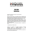
World of Automation
Chapter 2: SLS-500 Series
www.hiquel.com
INDEX
INDEX
2
Chapter 2: SLS-500 Series
.01 INFO programmable controllers
.02 INFO programming
.03 INFO SLS-500 series
.04 INFO control-regulate with SLS-500
.05 INFO automation with SLS-500
.06 INFO SLS-500-Configurator
.07 INFO remote control with SLS-500
.08 INFO compact with SLS-500
.09 INFO module overview SLS-500
.10 SLS-510/SLS-520 Starter Kits
.11 SLS-510/SLS-520 compact controls
.12 SLS-500-CAN / SLS-500 Starter Kits
.13 SLS-500-CAN base module
.14 SLS-500 base module
.15 SiConfig - Software
.16 TERM4
.17 SLS-8207
HIQUEL 2009
X01.00
HIGH QUALITY ELECTRONICS
2:00
Basically there are two different PLC-series in the HIQUEL product
range, the SLS-86 and the SLS-500. Both are modular concepted and
can be used as central and/or distributed PLC systems. Due to the fact
that a base module can be combined with a broad range of expansion
modules both PLC series are very flexible and can therefore fit
individual demands. For both series there are also compact controls
available.
The SLS-86 and the SLS-500 are programmed without special software
knowledge but with different software programs.
in
U
0-10V
SLS-500 Series: complete bit, analogue and text processing
out
various SLS-500 base modules (SLS-500-CAN, SLS-500)
broad range of SLS-500 expansion modules (local and remote versions of all modules available)
SLS-500 compact modules (SLS-510, SLS-520)
DIN
RS485
RS232
building / industrial automation
Structured control
-600m
RTC
SLS-86 Series: bit processing
SLS-86 base modules
broad range of SLS-86 expansion modules (local and remote versions of all modules available)
SLS-86 compact module -HI86
9 * 9=81
SLS I/O
7
4
1
0
local connection
SLS-86
8
5
2
.
9
6
3
=
/
*
+
SLS I/O
remote connection using CAT5 cable
base module
remote connection
SLS I/O
local connection
up to 31
I/O modules
local
remote
HIQUEL 2009
X01.00
HIGH QUALITY ELECTRONICS
2:01
SLS-500-Configurator / SoftwirePLUS
Programming
SLS-500-Configurator
in
Series: SLS-500, SLS-500-CAN, SLS-510,SLS-520
U
0-10V
SLS-500-Configurator software is simple to use
with a user-friendly graphic configuration which
cuts costs to a minimum and is the basis for
efficient processing of building management
and industrial automation tasks.
out
Complete analogue, bit and text processing.
Easy adjustment by integrated scaling and
arithmetic operations.
DIN
Pre-programmed function modules (PID, Speed etc.)
RS485
Easy RTC+Calendar programming: time/date/year...
Online visualisation and simulation of functions
Language selection by mouse click German or English
RS232
SoftwirePLUS/SoftWIRE
Series: SLS-86, HI-86
RTC
Comfortable programming via wiring (ladder)
diagram (SoftwirePLUS) with online visualisation
of I/O´s, automatically creates complete paper
documentation.
9 * 9=81
7
4
1
0
8
5
2
.
9
6
3
=
/
*
+
Optimised display layout and automated address
allocation for easy handling.
No limitation of program elements on one ladder
rung. Series and parallel circuit of contacts and coils.
Latching contact, bistable, set and reset function,
memories, star-delta-run-up, time functions...
Software features: easy online visualisation and
simulation of functions.
Language selection simply by mouse click German, English, Italian, Spanish, French...
2:02
HIQUEL 2009
X01.00
HIGH QUALITY ELECTRONICS
Complete bit, analogue and text processing
The PLC-series SLS-500 is a central and/or distributed PLC system
with modular concept. The SLS-510 and the SLS-520 are compact
controls of the SLS-500 series.
in
The base module allows easy and cost-effective communication with up to 32 different expansion
modules over a bus length of up to 600m. The modules can be connected either locally by recessed side
connectors for side by side DIN rail mounting or remotely via CAT5 cable.
U
0-10V
SLS-500 expansion modules
SLS-500 base modules
Connection: local and remote versions
of all modules available
SLS-500-CAN
SLS-500
digital input modules 24Vdc or 100-240Vac
out
digital output modules, relays, transistor or
photomos
DIN
analogue I/O modules 0-10V or 0-20mA
SLS-500 compact
modules
lighting dimmer module with 1 dimmed output 230V~
SLS-510
temperature detection modules for Pt100- and
PT1000 sensors
SLS-520
16bit analogue input modules; 0-10V or 0-20mA
RS485
incremental encoder input with prescaled output pulses
Area of use:
open protocol RS232/RS485 interface modules
r industrial automation
RS232
interface modules for GSM (text messaging) modem
r process technology
room temperature detection modules with 4 inputs
r building management
building / industrial automation
SLS-500 Series
room temperature controller
r air conditioning
r window, door and
gate control
r material handling
r lighting control
r liquid level control in tanks
and pumping systems
RTC
r bespoke systems
9 * 9=81
7
4
1
0
base module
local (C)
8
5
2
.
9
6
3
=
/
*
+
remote (D)
possible connections:
Modbus
HIQUEL 2009
X01.00
HIGH QUALITY ELECTRONICS
2:03
building and facility management systems
Control - Regulate
Building technology
in
Programming
Title:
U
Timer mit variabler Zeit
HIGH QUALITY ELECTRONICS
L1.DI1
L1.DI1
In
In
Reset
Reset
Time1
Time1
Time2
Time2
11
Out
Out
L1.DO1
L1.DO1
TIMER
TIMER
Recycler
Recycler Hi
Hi
Zeit2
Zeit2
SLS-500 modules can be locally or remotely
connected to an internal RS485 network
in an easy and cost-effective way.
L1.DO2
L1.DO2
^^
L1.DI5
L1.DI5
0-10V
COUNT
COUNT SET
SET
11
In
In =
=
Value
Value
L1.DO2
L1.DO2
SLS-500 can be integrated within standard
applications (light switches, twilight
sensors, temperature sensors, printers,
modems, displays etc.)
·
· Second
Second
Zeit2
Zeit2
L1.DI4
L1.DI4
COUNT
COUNT SET
SET
55
In
In =
=
Value
Value
Zeit2
Zeit2
Simple wiring of solar heating controls,
building controls, heating systems
and alarms.
out
DIN
Open protocol communication and
networking is a standard feature of the
SLS-500 product line.
RS485
Heating-Ventilation-Air Conditioning
Simple HVAC control with pre-programmed
PID controller and remote room
control modules (remote control).
RS232
SLS-500 modules are ideal to re-equip
office buildings, schools, greenhouses etc.
SLS-controls are perfectly suited for
contracting companies: bespoke
building management systems
Comfortable and economical: HVAC,
light control, solar heating systems - all
controlled from one system
RTC
9 * 9=81
7
4
1
0
8
5
2
.
9
6
3
=
Control-Monitoring-Alarming
/
*
+
Open protocol communication and
networking is a standard feature of the
SLS-500 product line.
The models offer perfect access control:
camera monitoring, identification
systems etc.
SLS-500 modules are ideal to re-equip
office buildings, schools, greenhouses etc.
The base module provides
cost-effective communication with
up to 32 extension modules over a
bus length of maximum 600m.
2:04
HIQUEL 2009
X01.00
HIGH QUALITY ELECTRONICS
Process technology
in
The modular structure allows system
changes to suit application alterations.
U
Suitable for process control with complex
functions processing large data volumes,
e.g. analogue values, nominal values,
meter readings or time parameters.
0-10V
Integration: printers, scanners, barcode
scanners, identification systems,
measuring systems, encoder modules…
out
DIN
RS485
Machine control
SLS-500 modules are suited to display,
compare and calculate analogue values
and texts.
RS232
Parameters or required values are changed
directly on the text display or via PC.
industrial automation technology
Automation
Installation in low profile control boxes
and switch boxes within the machine is
possible through the modular concept.
Flexible program exchange by external
memory card.
RTC
9 * 9=81
BMS applications
SLS-500 modules can be combined to fit
various requirements for digital thermostats
GSM modems, scanners, access
systems…
7
4
1
0
8
5
2
.
9
6
3
=
/
*
+
Electrical wiring installations of
SLS-Controllers are highly cost-efficient.
Assembly of large networks is possible
with SLS-Controller.
Open protocol communication and
networking is standard.
HIQUEL 2009
X01.00
HIGH QUALITY ELECTRONICS
2:05
programming with SLS-500-Configurator
Programming
SLS-500-Configurator uses a totally new approach offering amazing possibilities
for programming PLC's.The whole SLS-500 Product series is programmed with
®
SLS-500-Configurator in Microsoft Power Point with full integration to other
Microsoft Office applications!
in
U
0-10V
out
DIN
Series: SLS-500, SLS-500-CAN, SLS-510, SLS-520
For the first time the powerful 'SLS-500
Configurator' offers a graphic environment in MS
PowerPoint for configuration and programming.
Microsoft Office is the most widely used software
package throughout the world and handling, as
well as all hot keys of the individual Office
components such as Word, Excel or Access are
identical between applications. Therefore, the
learning curve with the 'SLS-500 Configurator'
software is dramatically reduced compared to a
proprietary software solution.
System configuration:
up to 32 I/O modules possible
Programming
Title:
Timer mit variabler Zeit
L1.DI1
L1.DI1
In
In
Reset
Reset
RS485
RS232
RTC
9 * 9=81
7
4
1
0
2:06
8
5
2
.
9
6
3
=
/
*
+
Out
Out
L1.DO1
L1.DO1
TIMER
TIMER
Recycler
Recycler Hi
Hi
Time1
Time1
Time2
Time2
11
Zeit2
Zeit2
L1.DO2
L1.DO2
^^
L1.DI5
L1.DI5
In
In =
=
Value
Value
L1.DO2
L1.DO2
·
· Second
Second
COUNT
COUNT SET
SET
11
The ‚SLS-500-Configurator' software combines
PowerPoint's graphic abilities with a user-friendly
graphic computer language supporting full bit-,
analogue-, and text processing. Of course all
popular elements, included in common PLC
programming systems, such as flags, inputs and
outputs, counters, time elements and edge
detection functions are integrated in the software.
However, there are special symbols for those
graphic parts of the program.
As normal for PowerPoint, text notes, Word
documents, Excel files, digital pictures and
even digital videos can be embedded to
create comprehensive documentation of your
plant while programming your PLC!
For documentation purposes simply print out the
project or export it to other office programs. For
example the contactor configuration of the wiring
diagram, triggered by a special part of the
software can be integrated. An audio file that
contains a description of the operational
sequence dictated by the programmer can be
added as well as a digital video showing the
correct mode of machine operation to guarantee
best basic knowledge for the maintenance staff
and future programmers when modifications are
required! It is also possible to embed whole
documents. For example with a simple mouse
click the user manual of a frequency converter is
opened as PDF file, the entire wiring diagram or
the operating guidelines are opened in Word
format. Of course, parts of the program can be
optionally printed out or exported easily to other
Microsoft Office programs.
A special feature of PowerPoint is the ability to
save all multimedia information in one single file.
Therefore, to reinstall the program only this file is
needed, as a compiler, which basically is an
integrated simulator, an online load module and
an online testing module are also integrated in
this PowerPoint file. No additional software is
needed to be able to work with the 'SLS-500Configurator'!
HIGH QUALITY ELECTRONICS
Zeit2
Zeit2
L1.DI4
L1.DI4
COUNT
COUNT SET
SET
In
In =
=
Value
Value
55
Zeit2
Zeit2
Simple-to-use graphic style flow diagram
software: automatic addressing, drop down symbol
library. Text, photo, audio & video notes on
program pages for future reference
Text Operation
++
Binary Operation
In
In =
=
Value
Value
>=
>=
Value
Value
Analoge Operation
**
!=
!=
const
const 00
||
//
<<
<<
const
const 11
^^
%
%
>>
>>
~~
++
&&
&&
=
=
--
||||
!!
In
In ?
?
Value
Value
Value
Value
==
In
In =
=?
?
Value
Value
Value
Value
<<
In
In =
=
Value
Value
Value
Value
<=
<=
In
In ?
?
Value
Value
Value
Value
?
?
-()
-()
In
In =
=?
?
Value
Value
Value
Value
=
=?
?
>=
>=
>>
!=
!=
0.0
0.0
Alarm
Alarm
Start the application
START
START
Periodic functions
Q
1ms
Q 1ms
Q
Q 10ms
10ms
Q
Q 100ms
100ms
>>
Directional connection
Constant functions
&
&
Markers
·
· Second
Second
==
Marker
Merker
SET
SET
Marker
Mr
<<
Value
Value
RESET
RESET
Marker
Merker
<=
<=
Text
Text
TOGGLE
TOGGLE
Marker
Merker
·
· Minute
Minute
·
· Hour
Hour
·
· Day
Day
·
· Week
Week
·
· Month
Month
·
· Year
Year
Real time clock
with calendar function:
¹
CLOCK
CLOCK
HH:MM:SS
HH:MM:SS
Out
Out
¹
CLOCK
CLOCK
TT.MM.YY
TT.MM.YY
Out
Out
CLOCK
Out
CLOCK
Out
¹ TT.MM.YY
TT.MM.YY HH:MM:SS
HH:MM:SS
¹
CLOCK
CLOCK
DDD
DDD
Out
Out
¹
CLOCK
CLOCK
WEEKxx
WEEKxx
Out
Out
¹
¹
CLOCK
CLOCK
HH:MM:SS
HH:MM:SS
HH:MM:SS
HH:MM:SS
CLOCK
CLOCK
TT.MM.YY
TT.MM.YY
TT.MM.YY
TT.MM.YY
Out
Out
Out
Out
Out
Out
CLOCK
CLOCK
¹ TT.MM.YY
TT.MM.YY HH:MM:SS
HH:MM:SS
TT.MM.YY
TT.MM.YY HH:MM:SS
HH:MM:SS
¹
¹
CLOCK
CLOCK
DDD
DDD
DDD
DDD
CLOCK
CLOCK
WEEKxx
WEEKxx
WEEKxx
WEEKxx
Out
Out
Out
Out
¹
CLOCK
CLOCK
HH:MM:SS
HH:MM:SS
¹
CLOCK
CLOCK
TT.MM.YY
TT.MM.YY
days of the week,
weeks of the year,
days,
months,
years,
date,
time
Out
Out
Out
Out
CLOCK
Out
CLOCK
Out
¹ TT.MM.YY
TT.MM.YY HH:MM:SS
HH:MM:SS
¹
CLOCK
CLOCK
DDD
DDD
¹
CLOCK
CLOCK
WEEKxx
WEEKxx
¹
CLOCK
CLOCK
HH:MM:SS
HH:MM:SS
¹
CLOCK
CLOCK
TT.MM.YY
TT.MM.YY
Out
Out
¹
CLOCK
CLOCK
DDD
DDD
Out
Out
¹
CLOCK
CLOCK
WEEKxx
WEEKxx
Out
Out
Out
Out
Out
Out
Out
Out
All program element addresses are automatically allocated and it
is simple to adapt the screen and printout to personal needs.
HIQUEL 2009
X01.00
HIGH QUALITY ELECTRONICS
overview
in
U
0-10V
RADIO
report
out
control
alarm
DIN
RS485
GSM
RS232
report
control
alarm
remote control and remote report
Remote
RTC
INTERNET
9 * 9=81
WEB based
7
4
1
0
Intranet
8
5
2
.
9
6
3
=
/
*
+
-
HIQUEL 2009
X01.00
HIGH QUALITY ELECTRONICS
2:07
compact modules
Compact modules
SLS-510 and SLS-520
8
in
U
0-10V
6
out
DIN
RS485
SLS-510
100-250Vac
SLS-520
20-250Vac/dc
Ideal in buildings for lighting and HVAC
systems, and in industrial applications
such as conveyor belts, hydraulic systems,
pumping systems, waste handling...
10A (SLS510) 5A (SLS520) relay outputs
Latching contacts, bi-stable, set and
reset functions, memories etc.
RTC
The software offers easy online
visualisation and simulation of functions.
9 * 9=81
7
4
1
0
8
5
2
.
9
6
3
=
Simple documentation (printing).
/
*
+
For AC and DC supply
Complete bit and text processing.
No limitation of circuits or function
blocks.
Manual settings on the module by means
of potentiometers on the front-plate.
Easy program exchange with memory
card (SLS520).
Simple combination of all time data,
e.g. RTC time, period, weekdays, calendar
week, days, months, years, date and time.
2:08
HIQUEL 2009
X01.00
HIGH QUALITY ELECTRONICS
overview
8
in
U
0-10V
6
out
DIN
RS485
RS232
RTC
9 * 9=81
7
4
1
0
HIQUEL 2009
X01.00
HIGH QUALITY ELECTRONICS
8
5
2
.
9
6
3
=
/
*
+
base and expansion modules SLS-500 / SLS-500-CAN
SLS-500 modules
2:09
SLS-510, SLS-520
overview
all you need to get you going - a starter kit:
SLS-510
SLS-520
in
Automation Software
U
Automation Software
Automation Software
0-10V
Automation Software
out
DIN
RS485
includes:
includes:
SLS-510-R 100-250 Vac 10A
serial interface cable
(programming cable)
CD-ROM Automation Software
input simulator
manual
SLS-520-R 20-250Vac/dc
serial interface cable
(programming cable)
CD-ROM Automation Software
input simulator
manual
SIM-Card (memory card)
RS232
Programming with SLS-500-Configurator:
Programming without special software knowledge, suitable for small 8/4 I/O applications.
The SLS-510 and SLS-520 are compact programmable (intelligent) relays that can be used in many fields including
industrial control and automation, and machinery control.
The SLS-510 has 8 digital inputs and 4 relay outputs, the SLS-520 has 8 digital inputs and 6 relay outputs. The user
program memory for both modules is 16 kB. The SLS-520 additionally features a SIM Card for easy program exchange
as well as module to module data transfers.
SLS-510 as well as SLS-520 are programmed with SLS-500-Configurator in Microsoft PowerPoint, with full integration
to other Microsoft Office applications. For more detailed information please refer to page 1:06.
The Real Time Clock (RTC) can be easily programmed for point of time switching, (to perform a function at a fixed
time/date) or time interval switching, (to perform a function between two times, dates, weeks, years etc). Days of the
week, weeks of the year, days, months, years, date and time can be easily combined.
Analogue values can be set using the external potentiometers on the front plate or by PC.
The analogue functions are used to monitor and evaluate different levels, pressures or temperatures. With the analogue
outputs you can control the rpm of a motor or the climate of a room and perform many other functions.
SLS-500-Configurator features on-line monitoring, simulation & status display of all I/O’s and internal program elements
on the PC. Programs can be simulated without a module connected.
It also automatically creates complete paper documentation.
All program element addresses are automatically allocated and it is simple to change the screen and printout.
RTC
9 * 9=81
7
4
1
0
8
5
2
.
9
6
3
=
/
*
+
compact control SLS-510 and SLS-520 starter kits
Starter Kits
Ordering information
part no
SLS-510-R-Starter Kit
SLS-510-R +Automation Software + download cable + manual + input simulator
SLS-520-R-Starter Kit
SLS-520-R + Automation Software + download cable + manual + input simulator + SIM Card
HIQUEL 2009
X01.00
HIGH QUALITY ELECTRONICS
2:10
overview
compact programmable relay module
supply voltage 100-250V~ (SLS-510), 20-250 V~=
(SLS-520)
8 digital inputs 100-250V~
4 SPNO outputs, max. 10A (SLS-510), 6 SPNO
outputs, max. 5A (SLS-520)
RS232 port for programming/monitoring (SLS-520)
Memory Card for simple program transfer (SLS-520)
LED indicators for inputs and outputs
2 potentiometers for timers and analogue values
16kB user-program memory
32 timers, 32 counters
real time clock (RTC) with calendar function
67.5mm DIN rail mount housing
graphical programming with ‘SLS-500-Configurator’
in Microsoft PowerPoint
8
in
U
100-250V
4/6
out
RS232
specification
SLS-510:
~
Di7
power consumption
output relay specification
Di8
Di6
Di5
Di4
Di3
Di1
L
Di2
supply voltage
RTC
Ue/Ie AC-15
Config
7
1 x 10 operations
43
44 Do4
33
34 Do3
24 Do2
Di8
Di7
Di6
Di5
Di4
SLS-510
100-250V~
SLS-520
24V= max 5mA
program memory
16kB
protection class
terminals
IP20
housing
IP50
screws
screw tightening torque
L
DIN
5
1 x 10 operations
electrical
input specification
+
~
Di2
SLS-520:
23
~
14 Do1
/
*
+
Di3
9
6
3
=
13
8
5
2
.
Di1
7
4
1
0
240V/4A
24V/4A
SPNO
mechanical
9 * 9=81
SLS-510 100-250V~
SLS-520 20-250Vac/dc
1W nominal
SLS-510 max 10A 250V~
SLS-510 max 5A 230V~
120V/5A
Ue/Ie DC-13
expected life time
N
compact control SLS-510 , SLS-520
SLS-510, SLS-520
pozidrive 1
0,6..0,8 Nm
weight
210g
dimensions
67.5 x 85 x 75mm
operating conditions
-15 to 55°C non condensing
*EN 60947-5-1 VDE 0435
CARD
ordering information
C4-6
Do6
Do5
Do4
C1-3
Do3
Do1
Do2
N
RS232
~
-
part no
SLS-510-R
SLS-Std-RS232
SLS-520-R
SLS-Std-RS232
supply
100-250V~
input
inp. galv. iso. *
output
outp. galv. iso.*
housing types
8x 100-250V~
no
4x SPNO
yes
E
8x 20-240V~=
no
6x SPNO
yes
E
download cable
20-250V~=
download cable
* measurement input galvanically isolated from the power supply
2:11
HIQUEL 2009
X01.00
HIGH QUALITY ELECTRONICS
SLS-500-CAN,
SLS-500
overview
all you need to get you going - a starter kit:
in
SLS-500CAN:
SLS-500-CAN-R 100-24 V=
(base module)
serial interface cable
(programming cable)
CD-ROM Automation Software
SIM-Card (memory card)
input simulator
manual
Automation Software
U
Automation Software
0-10V
out
DIN
SLS-500:
SLS-500-R 100-24 V= (base
module)
serial interface cable
(programming cable)
CD-ROM Automation Software
SIM-Card (memory card)
input simulator
manual
Automation Software
Automation Software
RS485
RS232
Programming with SLS-500-Configurator:
Programming without special software knowledge, suitable for small (8/6 I/O) and large (up to 250 I/O)
applications.
The SLS-500 bases modules are modular programmable (intelligent) relays that can be used in many fields including
industrial control, automation, and building management systems.
The base modules can communicate with up to 32 expansion modules either directly connected (local) or via CAT5
cable (remote). It is possible to connect up to 250 I/O over a maximum distance of 600m to one base module.
A broad range of expansion module types is available: including digital I/O, analogue I/O, room controller (FBR),
lighting dimmer, temperature inputs, encoder inputs, stepper motor outputs, SMS-Module etc in local and remote
versions (see tables on page 01:09 and 01:10).
The base modules of the SLS-500 product range (SLS-500-CAN, SLS-500) are programmed with SLS-500Configurator in Microsoft PowerPoint, with full integration to other Microsoft Office applications. For more detailed
information please refer to page 1:06.
With HTPC (Touch Panel) or TERM4 you can control or change values, display texts or change and update values,
menu structure and SCADA software (HTPC)
The Real Time Clock (RTC) can be programmed easily for time switching, (to perform a function at a fixed time/date)
or time interval switching, (to perform a function between two times, dates, weeks, years etc). Analogue values can be
set using the external potentiometers on the front plate (SLS-500) or by PC. The analogue functions are used to
monitor and evaluate different levels, pressures or temperatures. With the analogue outputs you can control the rpm of a
motor or the climate of a room and perform many other functions.
SLS-500, SLS-500 CAN starter kits
Starter Kits
RTC
9 * 9=81
7
4
1
0
8
5
2
.
9
6
3
=
/
*
+
ordering information
part no
SLS-500-CAN-R-Starter
SLS-500-CAN-R + Automation Software + download cable + manual + input simulator + SIM Card
SLS-500-R-Starter Kit
SLS-Std-RS232
SLS-500-R + Automation Software + download cable + manual + input simulator + SIM Card
download cable
HIQUEL 2009
X01.00
HIGH QUALITY ELECTRONICS
2:12
overview
system base module
supply voltage 24V=
8 digital inputs 24V=, inputs 1-4 are dual
digital/analogue 0-10V
8
in
6 SPNO outputs, max. 5A
RS232 interface for programming/monitoring
U
CAN Bus port via CAT5
RS485 port connects up to 32 SLS-500-I/O modules
+
LED indicators for inputs and outputs
48kB user-program memory
0-10V
graphical programming with
out
Di8
Di7
Di5
6
Di6
DI4/Ai4
DI2/Ai2
DI3/Ai3
M-
CAN
67.5mm DIN rail mount housing
DI1/Ai1
-
timers, counters, RTC with calendar function,
analogue- and text processing
CARD
‘SLS-500-Configurator’ in Microsoft PowerPoint
DIN
RS232
specification
Do5
Do6
L
L
L
C4-6
Do1
Do3
L
C1-3
Do2
L L
Do1
L+
RS485
RS485
+
supply voltage
24V= ±10%
power consumption
output relay specification
1W nominal
max. 5A 230V~
L
Ue/Ie AC-15
120V/1,5A
N
Ue/Ie DC-13
24V/1A
mechanical
SLS-500-CAN
local connection
7
1 x 10 operations
up to 32
I/O modules
5
1 x 10 operations
electrical
input specification
24V=
program memory
64kB
protection class
terminals
IP20
housing
IP50
max. 5 mA
screws
pozidrive 1
screw tightening torque
0,6..0,8 Nm
weight
210g
dimensions
67.5 x 85 x 75mm
operating conditions
-15 to +55 °C non condensing
resolution
analogue inputs and outputs
up to 32
I/O modules
RTC
9 * 9=81
*EN 60947-5-1 VDE 0435
up to 32
I/O modules
7
4
1
0
8
5
2
.
9
6
3
=
/
*
+
SLS-500-CAN
remote connection using
standard CAN cable
ordering information
part no
RS232
SLS-500- I/O
60V~=/2A
SPNO
remote connection
Ue
DC-13 photomos
expected life time
240V/1A
SLS-500-CAN master controller
SLS-500-CAN
supply
input
inp. galv. iso.*
output
outp. galv. iso.*
housing types
SLS-500-CAN-R
24V=
8x 24V=
no
6x SPNO
yes
E
SLS-500-CAN-S
24V=
8x 24V=
no
6x Photomos
yes
E
SLS-500-CAN-R-4AiU-3AoU 24V=
4x 24V=
no
3x SPNO
yes
E
SLS-500-CAN-R-4AiU-3AoI
24V=
4x 24V=
no
3x SPNO
yes
E
SLS-500-CAN-R-4AiI-3AoU
24V=
4x 24V=
no
3x SPNO
yes
E
SLS-500-CAN-R-4AiI-3AoI
24V=
4x 24V=
no
3x SPNO
yes
E
SLS-500-SIM
SIM-Card memory 64kB
SLS-500-BUS
bus termination for external I/O modules
* measurement input galvanically isolated from the power supply
HIQUEL 2009
X01.00
HIGH QUALITY ELECTRONICS
2:13
overview
system base module
supply voltage 24V=
8 digital inputs 24V=, inputs 1-4 are dual
digital/analogue 0-10V
8
in
6 SPNO outputs, max. 5A
RS232 interface for programming/monitoring
U
RS485 port connects up to 32 SLS-500-I/O modules
LED indicators for inputs and outputs
0-10V
2 potentiometers
16kB user-program memory
+
-
6
timers, counters, RTC with calendar function,
analogue- and text processing
DIN
Di7
graphical programming with
Di8
Di6
DI4/Ai4
67.5mm DIN rail mount housing
Di5
DI3/Ai3
DI1/Ai1
DI2/Ai2
M-
out
‘SLS-500-Configurator’ in Microsoft PowerPoint
CARD
RS232
specification
RS232
Do6
C4-6
Do5
Do4
C1-3
Do3
Do2
Do1
RS485
RS485
supply voltage
24V= ±10%
+
power consumption
1W nominal
L
output relay specification
Ue/Ie AC-15
L+
SLS-500 master controller
SLS-500
L L
N
L
L
L
Ue/Ie DC-13
L
Ue DC-13 Photomos
SLS-500 I/O
local connection
SLS-500
SLS-500 I/O
remote connection using
standard CAT5 cable
RTC
remote connection
8
5
2
.
9
6
3
=
240V/1A
60V=/2A
expected life time
mechanical
SPNO
7
1 x 10 operations
electrical
input specification
1 x 10 operations
max. 5 mA
24V=
5
program memory
16kB
protection class
terminals
housing
IP20
IP50
screws
pozidrive 1
screw tightening torque
0,6..0,8 Nm
weight
210g
dimensions
67.5 x 85 x 75mm
operating conditions
-15 to +55°C non condensing
*EN 60947-5-1 VDE 0435
SLS-500 I/O
9 * 9=81
7
4
1
0
max. 5A 230V~
120V/1,5A
24V/1A
local connection
/
*
+
up to 32
I/O modules
ordering information
part no
supply
input
inp. galv. iso. *
Gehäusetypen
output
outp. galv. iso.*
housing types
SLS-500-R
24V=
8x 24V=
no
6x SPNO
yes
E
SLS-500-S
24V=
8x 24V=
no
6x Photomos
E
SLS-500-R-4AiU-3AoU 24V=
4x 24V=
no
6x SPNO
yes
yes
SLS-500-R-4AiU-3AoI
24V=
4x 24V=
no
6x SPNO
E
SLS-500-R-4AiI-3AoU
24V=
4x 24V=
no
6x SPNO
yes
yes
SLS-500-R-4AiI-3AoI
24V=
4x 24V=
no
6x SPNO
yes
E
SLS-500-SIM
SIM-Card memory 64kB
SLS-500-BUS
bus termination for external I/O modules
E
E
*measurement input is galvanically isolated from the power supply
2:14
HIQUEL 2009
X01.00
HIGH QUALITY ELECTRONICS
overview
Communication software for SLS-500
No licence needed
RS485
Direct communication through RS232 and RS485
or SIVIEWServer
GRID display
simply Configuration
RS232
password protection
easy to use menu tree
Win98, Win2000, WinXP
special support for date and time
Touchscreen capability
No limits in views or entries
Increases the capacity of your visualisation software
Downloadable from www.hiquel.com
SLS-500-Configurator on PC#1
SiConfig on PC#2
SLS-500 Configurator on PC#3
SiConfig on PC#4
TCP/IP
RS232
Server PC with HIQUEL-SiView
Server software and
a serial interface
SLS-500-SiConfig communication software
SLS-500-SiConfig
ordering information
Please download this program from www.hiquel.com
HIQUEL 2009
X01.00
HIGH QUALITY ELECTRONICS
2:15
overview
LC backlit display
RS232
4 lines with 20 characters each line
character size 3x5mm
9 control keys with symbols
integrated RS232 interface
error tolerant protocol for
data transmission
front panel mounting 195x110mm
25mm deep
specification
supply voltage
nominal voltage +10% / -15%
duty cycle
protection class
100%
weight
660g
Drivers, and an easy to read manual describing
all functions are supplied. TERM4 is very easily
connected to all host systems such as PLCs or
PC´s.
IP54 (front side)
dimensions
width
195mm
height
110mm
depth
operating conditions
The HIQUELTERM4 text display is designed
for low-end visualisation applications and control
tasks within the field of industrial automation.
A compact, robust case has a liquid crystal display
with 4 lines and 20 characters on each line plus
a key pad with 9 keys. Each key has a unique
symbol. TERM4 is designed for monitoring alarms,
displaying parameters, changing menu structures
and displaying messages.
TERM4 text display
TERM4
40mm
-20 to +40°C non condensing
TERM4 is suited for use with both our SLS-86
and SLS-500 systems. With the TERM4 text
display it is easy to change the date, time and
other settings, without PC, independently of the
software.
ordering information
part no
TERM4
type
supply
input
-
24V= 2W
-
Gehäusetypen
inp. galv. iso.*
output
outp. galv. iso.*
-
-
-
housing types
special
* measurement input galvanically isolated from the power supply
HIQUEL 2009
X01.00
HIGH QUALITY ELECTRONICS
2:16
SLS-8207 power supply 2A
SLS-8207
overview
power supply 100-240V~
output 24V= 2A
LED-indicaticators for input power supply
LED-indicaticators for output power supply
25mm DIN-rail mount housing
SLS-8207 power supply
specification
power supply
100-240V~ ±20%
frequency
input voltage
50-60Hz
buffer time
0.24 A / 230V~
min.10ms / 230V~
output voltage
ripple
24Vdc, ±5%
<100mVss incl. spikes
output current
2A (48 W)
typical 90%
efficiency
loss power
parallel operated
case
24V=
M- (mass)
GND (ground)
mounting
!!! IMPORTANT !!!
typical 5W
yes
ABS/PC
dimensions
DIN-rail mount housing
25 x 80 x 76mm
operating conditions
-15 to +50 °C non condensing
M- must be always grounded.
All converters must be grounded.
All the GND must be linked.
All modules have 24V and M- supply.
ordering information
part no
SLS-8207
supply
input
inp. galv. iso.*
100-240V~
-
yes
Gehäusetypen
output
outp. galv. iso.*
24V=
yes
housing types
J
* measurement input galvanically isolated from the power supply
2:17
HIQUEL 2009
X01.00
HIGH QUALITY ELECTRONICS