1
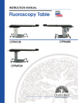
INSTRUCTION MANUAL
Fluoroscopy Table
CFPMFXH
integrated headrest top
CFPM100
integrated headrest top
CFPM400
integrated headrest top
CFPMFXH
rectangular top
CFPM100
rectangular top
CFPM400
rectangular top
© Copyright 2007
OAKWORKS®, Inc.
Notice
Manual Part # MMMNST0008, rev.02.19.10
1st Edition, October 2007
2nd Edition, March 2008
3rd Edition, February 2009
4th Edition, September 2009
Printed in U.S.A.
All rights are reserved. No part of this
document may be photocopied, reproduced
or translated to another language without prior
written consent of OAKWORKS®, Inc.
OAKWORKS® is a registered
trademark of OAKWORKS®, Inc.
The information contained in this document
is subject to change without notice and
should not be construed as a commitment by
OAKWORKS®, Inc.
OAKWORKS®, Inc. assumes no responsibility for
any errors that may appear in this document nor does it make expressed or implied
warranty of any kind with regard to this
material, including, but not limited to, the
implied warranties
of merchantability and fitness for a
particular purpose.
OAKWORKS®, Inc. shall not be liable for incidental or consequential damages in connection with or arising out of the furnishing,
performance, or use of this document and
the program material which it describes.
TABLE OF CONTENTS
Symbol Identification ...........................................................................
pg 1
Indications & Contraindications .........................................................
pg 2
Warnings & Precautions .......................................................................
pg 2
Section I: Product Description & Photo
CFPMFXH - 22” x 84” Integrated Headrest Top....................
pg 4
CFPMFXH - 24” x 80” Rectangular Top................................
pg 5
CFPM100 - 22” x 84” Integrated Headrest Top.......................... pg 6
CFPM100 - 24” x 80” Rectangular Top..........................................
pg 7
CFPM400 - 22” x 84” Integrated Headrest Top.......................... pg 8
CFPM400 - 24” x 80” Rectangular Top..........................................
pg 9
Section II: Directions for Use
Adjusting Height (CFPM100 & 400 only)............................................... pg 10
Adjusting Tilt & Longitudinal Travel (CFPM400 only)....................... pg 11
Patient Positioning Strap ............................................................................
pg 11
Adjusting Table Top Pad ................................................................................
pg 12
Adjusting Cranial Positioning Pads (integrated headrest only)........
pg 12
Moving the Fluoroscopy Table ........................................................................ pg 13
Emergency Stop ...................................................................................................... pg 13
Usable Imaging Area Diagrams
CFPMFXH & CFPM100 - integrated headrest tops.................. pg 14
CFPMFXH & CFPM100 - rectangular tops................................. pg 15
CFPM400 - integrated headrest tops........................................ pg 16
CFPM400 - rectangular tops....................................................... pg 17
Weight Capacity Limitations ............................................................................. pg 18
Section III: Troubleshooting
Ground Point Testing ........................................................................................... pg 19
If the table top will not change height or tilt ..........................................
pg 19
Hand & Foot Control Replacement Instructions .................................. pg 20
Section IV: Product Care and Maintenance ...................................................... pg 21
TABLE OF CONTENTS
TABLE OF CONTENTS
TABLE OF CONTENTS
TABLE OF CONTENTS
TABLE OF CONTENTS
Section V: Optional Accessories
Carbon Fiber Arm Board ............................................................
pg 22
Patient Positioning Strap ............................................................
pg 22
Spine Positioning System ...............................................................
pg 23
Fluoro Extender ...........................................................................
pg 23
Section VI: Product Identification
.....................................................
pg 24
power cord variables ...........................................................................
pg 25
Section VII: List of Parts ...............................................................
pg 26
Section VIII: Specifications CFPMFXH, 100 & 400.............................
pg 27
Guidance & Manufacturers Decloration - Emissions (all systems).....
pg 28
Recommended Separations - Distances from the CFPM400 ..........
pg 29
Guidance & Manufacturers Decloration - Immunity .....................
pg 30
Guidance & Manufacturers Decloration - Emmissions
(Equipment that is NOT life supporting) ................................
pg 31
Contact Information ..................................................................
Back Cover
LIFETIME LIMITED WARRANTY
View complete warranty details at www.oakworks.com
All warranties are limited to factory-provided replacement parts, factory repair or replacement, at the discretion of OAKWORKS®. OAKWORKS® only covers parts and labor on field
repair of stationary products.
All warranties exclude damage caused by improper set-up, accident, abuse, misuse, neglect,
use for other than intended purpose or reasonable wear such as tears in the upholstery.
All warranties are invalidated by non-factory modifications and unauthorized repairs, which
will immediately terminate all liability by OAKWORKS® for the product or damages caused by its
use.
The buyer and its customers shall be responsible for proper set-up and use of the products
as well as any supervision required for safety. In no event shall OAKWORKS® be liable for any
special, indirect, consequential, incidental, exemplary or punitive damages or costs. Use of
non-approved cleaning solutions voids the guarantee on all fabrics.
The warranties set forth herein are the sole and exclusive warranties provided by
OAKWORKS®. There are no other warranties, representations or guarantees provided by
OAKWORKS® either expressed or implied, including warranties of merchantability and fitness
for a particular purpose. Warranty valid with proof of purchase.
SYMBOL IDENTIFICATION
SYMBOL IDENTIFICATION
This symbol, when used in this manual and on product labels, represents a caution
warning. Be sure to read and comply with all precautions and warnings.
This symbol, when used in this manual and on product labels, warns against an
electrical shock hazard. Be sure to observe and comply with all warnings.
This symbol, when used in this manual and on product labels, indicates the potential
of exposure to harmful x-rays. Be sure to read and comply with all warnings.
This symbol, when used in this manual and on product labels, indicates that the
table and components are a Type B Applied Part pursuant to IEC 601.1 and EN
60601-1: 1990.
This symbol, when used in this manual or on product labels, indicates a Protective
Earth (Ground) Terminal.
US
C
LISTED
This symbol when used in this manual or on product labels, warns that during transport there should be no stacking of containers.
US
C
US
C
LISTED
LISTED
This symbol, when used in this manual or on product labels, indicates that
the product should be protected from moisture. The humidity specifications for
Transport & Storage are listed on page 23.
US
C
LISTED
This symbol, when used in this manual or on product labels, indicates that information is
given regarding the recommended temperature limits during transport and storing.
US
C
LISTED
This symbol, when used in this manual or on product labels, indicates the date of
manufacture of the device.
~
This symbol, when used in this manual or on product labels, indicates alternating
current (AC).
US
C
LISTED
This symbol, when used in this manual or on product labels, indicates direct current (DC).
---1
SYMBOL IDENTIFICATION
The OAKWORKS® Fluoroscopy Table is a radiographic table intended for use with
mobile or compact stationary C-arm Fluoroscopy Systems. It is ideally suited for
pain management imaging and therapeutic procedures.
WARNINGS / PRECAUTIONS
WARNINGS / PRECAUTIONS
WARNINGS / PRECAUTIONS
INDICATIONS
The OAKWORKS Fluoroscopy CFPM tables are indicated for use with mobile or
compact C-arm Fluoroscopy Imaging Systems where the x-ray generator is located
below the tabletop. These tables are suitable to use for diagnostic x-ray imaging and
imaging during therapeutic procedures such as spinal injections,
vertebroplasty procedures and other pain management procedures. These tables
may be used for surgical and non-surgical procedures.
CONTRAINDICATIONS
The OAKWORKS Fluoroscopy Table should not be used with Fluoroscopy systems
having intensifier screens or film cassettes larger than 12 inches (30 cm) when an
oblique angle of view is being used.
The table is not designed for and should not be used with Magnetic Resonance
Imaging procedures.
WARNINGS
Improper use of this device can cause injury. Be sure to read all operating
instructions prior to use.
Weight limit (patient and accessories):
Carbon Fiber Top: 227 kg / 500 lbs. distribured evenly
Do not sit beyond warning line on carbon fiber top.
Lock casters when mounting and dismounting.
The table utilizes four locking casters to permit movement of the table
within the imaging suite. Accidental movement of the table may occur. Lock
casters prior to accomplishing imaging of the patient.
There may be pinch points under the table top. Do not have any body part under
the top when the table is in motion.
Be certain that the table is completely lowered prior to discharging an ambulatory
patient. The patient may lose balance and fall. (CFPM100 & 400 only)
The CFPMFXH is a fixed height table. It is recommended that all patients are assisted
onto the table (physical assistance & step stools with side rails is recommended.)
Patient Safety Strap must be secured prior to using the Trendelenburg/Reverse
Trendelenburg function. (CFPM400 only)
2
WARNINGS / PRECAUTIONS
WARNINGS: (CONTINUED)
Electrical Shock Hazard. (CFPM100 & 400 only) The power supply/control module is located inside lifting column and under the top. No user serviceable parts are
inside. Refer servicing to qualified personnel. Unplug wall connector prior to contact with any cables connected to the power supply.
Medical Electrical Equipment needs special precautions regarding EMC and needs
to be installed and put into service according to the EMC information provided in
the Accompanying Documents. (CFPM100 & 400 only)
Portable and Mobile RF Communications Equipment can affect Medical Electrical
Equipment. (CFPM100 & 400 only)
The CFPM100 & 400 (only) should not be used adjacent to or stacked with other
equipment due to the risk of electronic interference. If adjacent or stacked use is
necessary, the table should be observed to verify normal
operation in the configuration in which it will be used.
The potential of exposure to harmful x-rays exists when this table is in use. The
use of adequate x-ray barrier devices is necessary to provide protection to both
the operator and the patient. X-ray barrier devices are recommended for the patient
outside of the intended target area to prevent exposure to scattered radiation from
the x-ray generating source.
The tabletop has a typical aluminum filtration equivalence of .62 mm as measured
at 100 kVp and a half-value layer (HVL) of 2.7 mm. (1.10 mm as measured at 100
kVp and a half value (HVL) of 3.6 mm)
• The OAKWORKS Fluoroscopy Table may be used for x-ray imaging
where the x-ray generator is located below the tabletop and the
image receptor is located above the tabletop. This is the recommended
method. This table may also be used for x-ray imaging where the x-ray
generator is located above the tabletop and the image receptor is located
below the tabletoop. This application will result in greater patient
exposure to x-rays. The operator must weigh this issue with the imaging
requirements and patient exposure issues.
• The Fluoroscopy Table may be used with the x-ray generator above
the tabletop and a film cassette located on the tabletop.
• The x-ray generator should never be located above the tabletop
when the OAKWORKS Fluoroscopy Table and the OAKWORKS Spine
Positioning System/Prone Pillow are used together. This type of use
requires that the x-ray generator is located below the tabletop and the
imaging intensifier or film cassette located above the tabletop.
Disconnect the power supply plug prior to cleaning any surfaces below or inside
of the base of the table.
3
WARNINGS / PRECAUTIONS
WARNINGS: (cont.)
PRODUCT DESCRIPTION - CFPMFXH
PRODUCT DESCRIPTION - CFPMFXH
22” X 84” INTEGRATED HEADREST TOP
Carbon Fiber Top with
Removable Table Top Pad
PRODUCT DESCRIPTION
Hand Rail
Integrated
Face Rest
with Face
Cushion
1)
2)
3)
Includes 3-pad Set:
1) 2” H x 12” S Q Pad
2) 4” H x 12” S Q Pad
3) Crescent Face Pad
Locking
Casters
(2 sets)
Table Specs* :
CAUTION
The CFPMFXH is a fixed height
table. It is recommended that
all patients are assisted onto
the table (physical assistance
& step stools with side rails is
recommended.)
• Height:
37” (91 cm) (optional heights are available)
• Width:
22” (56 cm)
• Length:
84” (214 cm)
• Patient
Capacity:
500 lbs.(227 kg.) distributed evenly
• Table Weight:
• Included
Accessories:
350 lbs. (159 kg.)
shipping 400 lbs.(182 kg.)
Table Top Pad with 1” Medical
Grade Foam & TerraTouch™ Fabric
1- 2”H x 12” SQ Head Rest Pad
1 - 4”H x 12” SQ Head Rest Pad
1 - Crescent Face Pad
• Optional
Accessories:
4
Carbon fiber arm board, Spine
Positioning System, Fluoro-Extender,
2” Table top pad
PRODUCT DESCRIPTION - CFPMFXH
PRODUCT DESCRIPTION - CFPMFXH
24” X 80” RECTANGULAR TOP
Carbon Fiber Top with
Removable Table Top Pad
PRODUCT DESCRIPTION
Hand Rail
Locking
Casters
(2 sets)
Table Specs* :
CAUTION
The CFPMFXH is a fixed height
table. It is recommended that
all patients are assisted onto
the table (physical assistance
& step stools with side rails is
recommended.)
• Height:
37” (91 cm) (optional heights are available)
• Width:
24” (61 cm)
• Length:
80” (203 cm)
• Patient
Capacity:
500 lbs.(227 kg.) distributed evenly
• Table Weight:
• Included
Accessories:
• Optional
Accessories:
350 lbs. (159 kg.)
shipping 400 lbs.(182 kg.)
Table Top Pad with 1” Medical
Grade Foam & TerraTouch™ Fabric
Carbon fiber arm board, Spine
Positioning System, Fluoro-Extender,
2” Table top pad
5
PRODUCT DESCRIPTION - CFPM100
PRODUCT DESCRIPTION - CFPM100
22” X 84” INTEGRATED HEADREST TOP
Carbon Fiber Top with
Removable Table Top Pad
TABLE OF CONTENTS
PRODUCT DESCRIPTION
Hand Rail
1)
2)
3)
Includes 3-pad Set:
1) 2” H x 12” S Q Pad
2) 4” H x 12” S Q Pad
3) Crescent Face Pad
Integrated
Face Rest
with Face
Cushion
Electronic
Lift Tower
Power kill
switch
Locking
Casters
(2 sets)
Table Specs* :
• Height Range:
22” - 40” (56 cm - 102 cm)
• Width:
22” (56 cm)
• Length:
84” (214 cm)
• Patient Capacity: 500 lbs.(227 kg.) distributed evenly
• Table Weight:
350 lbs. (159 kg.)
shipping 400 lbs.(182 kg.)
• Controls:
1 foot control
• Included:
Table Top Pad with 1” Medical Grade
Foam & TerraTouch™ Fabric
1- 2”H x 12” SQ Head Rest Pad
1 - 4”H x 12” SQ Head Rest Pad
1 - Crescent Face Pad
• Optional:
Carbon fiber arm board, Spine Positioning
System, Fluoro-Extender, 2” Table top pad
International Electric Configurations
• Table Options:
ELECTRICAL SPECIFICATIONS - CFPM100
North America
Designed For:
Europe
Input Service
120 VAC/15 amps/60Hz
220 VAC/10 amps/50Hz
Current Draw
5.8 amps
3.0 amps
Maximum Momentary Current Consumption
9.0 amps
4.5 amps
Voltage to Actuators
120 VDC
220 VDC
Class I Equipment
Class I Equipment
Electric Shock Protection
Tabletop Applied Part
Type B Applied Part
Mode of Operation
US
C
LISTED
6
Type B Applied Part
Continuous Operation
@ 10% Duty Cycle
Continuous Operation
@ 10% Duty Cycle
US
C
LISTED
PRODUCT DESCRIPTION - CFPM100
PRODUCT DESCRIPTION - CFPM100
24” X 80” RECTANGULAR TOP
Carbon Fiber Top with
Removable Table Top Pad
TABLE OF CONTENTS
Hand Rail
Electronic
Lift Tower
Power kill
switch
Locking
Casters
(2 sets)
Table Specs* :
• Height Range:
22” - 40” (56 cm - 102 cm)
• Width:
24” (61 cm)
• Length:
80” (203 cm)
• Patient Capacity: 500 lbs.(227 kg.) distributed evenly
• Table Weight:
350 lbs. (159 kg.)
shipping 400 lbs.(182 kg.)
• Controls:
1 foot control
• Included:
Table Top Pad with 1” Medical Grade
Foam & TerraTouch™ Fabric
• Optional:
Carbon fiber arm board, Spine Positioning
System, Fluoro-Extender, 2” Table top pad
International Electric Configurations
• Table Options:
ELECTRICAL SPECIFICATIONS - CFPM100
North America
Designed For:
Europe
Input Service
120 VAC/15 amps/60Hz
220 VAC/10 amps/50Hz
Current Draw
5.8 amps
3.0 amps
Maximum Momentary Current Consumption
9.0 amps
4.5 amps
Voltage to Actuators
120 VDC
220 VDC
Class I Equipment
Class I Equipment
Electric Shock Protection
Tabletop Applied Part
Type B Applied Part
Mode of Operation
Type B Applied Part
Continuous Operation
@ 10% Duty Cycle
US
C
LISTED
Continuous Operation
@ 10% Duty Cycle
US
C
LISTED
7
PRODUCT DESCRIPTION - CFPM400
PRODUCT DESCRIPTION - CFPM400
22” X 84” INTEGRATED HEADREST TOP
PRODUCT DESCRIPTION
Carbon Fiber Top with
Removable Table Top Pad
1)
Integrated
Face Rest
with Face
Cushion
2)
Hand Rail
Electronic
Lift Tower
Power kill
switch
3)
Locking
Casters
(2 sets)
Includes 3-pad Set:
1) 2” H x 12” S Q Pad
2) 4” H x 12” S Q Pad
3) Crescent Face Pad
Table Specs* :
• Height Range:
26” - 44” (66 cm - 112 cm)
• Width:
22” (56 cm)
• Length:
84” (214 cm)
• Patient Capacity: 500 lbs.(227 kg.) distributed evenly
• Table Weight:
475 lbs. (216 kg.)
shipping 525 lbs.(238 kg.)
• Controls:
1 foot control, 1 hand control
• Included:
Patient Positioning Strap
Table Top Pad with 1” Medical Grade
Foam & TerraTouch™ Fabric
1- 2”H x 12” SQ Head Rest Pad
1 - 4”H x 12” SQ Head Rest Pad
1 - Crescent Face Pad
• Optional:
Carbon fiber arm board, Spine Positioning
System, Fluoro-Extender, 2” Table top pad
International Electric Configurations
• Table Options:
ELECTRICAL SPECIFICATIONS - CFPM400
North America
Designed For:
Input Service
Europe
120 VAC/15 amps/60Hz
220 VAC/10 amps/50Hz
Current Draw
8.2 amps
4.5 amps
Maximum Momentary Current Consumption
12.3 amps
6.7 amps
24V Top, 120V Column
24V Top, 220V Column
Class I Equipment
Class I Equipment
Voltage to Actuators
Electric Shock Protection
Tabletop Applied Part
Type B Applied Part
Mode of Operation
US
C
LISTED
8
Type B Applied Part
Continuous Operation
@ 10% Duty Cycle
Continuous Operation
@ 10% Duty Cycle
US
C
LISTED
PRODUCT DESCRIPTION - CFPM400
PRODUCT DESCRIPTION - CFPM400
24” X 80”” RECTANGULAR TOP
Carbon Fiber Top with
Removable Table Top Pad
PRODUCT DESCRIPTION
Hand Rail
Electronic
Lift Tower
Power kill
switch
Locking
Casters
(2 sets)
Table Specs* :
• Height Range:
26” - 44” (66 cm - 112 cm)
• Width:
24” (61 cm)
• Length:
80” (203 cm)
• Patient Capacity: 500 lbs.(227 kg.) distributed evenly
• Table Weight:
475 lbs. (216 kg.)
shipping 525 lbs.(238 kg.)
• Controls:
1 foot control, 1 hand control
• Included:
Patient Positioning Strap
Table Top Pad with 1” Medical Grade
Foam & TerraTouch™ Fabric
• Optional:
Carbon fiber arm board, Spine Positioning
System, Fluoro-Extender, 2” Table top pad
International Electric Configurations
• Table Options:
ELECTRICAL SPECIFICATIONS - CFPM400
North America
Designed For:
Input Service
Europe
120 VAC/15 amps/60Hz
220 VAC/10 amps/50Hz
Current Draw
8.2 amps
4.5 amps
Maximum Momentary Current Consumption
12.3 amps
6.7 amps
24V Top, 120V Column
24V Top, 220V Column
Class I Equipment
Class I Equipment
Voltage to Actuators
Electric Shock Protection
Tabletop Applied Part
Type B Applied Part
Mode of Operation
Type B Applied Part
Continuous Operation
@ 10% Duty Cycle
US
C
LISTED
Continuous Operation
@ 10% Duty Cycle
US
C
LISTED
9
DIRECTIONS FOR USE
DIRECTIONS FOR USE
DIRECTIONS FOR USE
The OAKWORKS® Fluoroscopy Table offers a variety of positioning capabilities for
diagnostic x-ray imaging and imaging during therapeutic procedures. Although
it was designed principally for use during pain management x-ray diagnostic
and therapeutic procedures, it may also be used for other diagnostic procedures involving x-ray imaging provided the instructions in this manual are
observed.
Should the use of this device create a circumstance under which the
patient could be over-exposed to the x-ray being used, discontinue use
immediately and determine an alternative radiology table or alternative x-ray
generating source to use.
ADJUSTING HEIGHT OF THE TABLE (CFPM100 & 400):
The CFPM100 & CFPM400 come complete with one foot control.
Operate the controls as shown below to raise or lower the height of the table.
Foot Control - IP68 approved:
Used only to change height of table
IP 68 Enclosures - IP rated as “dust tight” and protected against complete, continuous submersion in water.
DOWN
When operating the table’s controls, be sure to observe all cautions and warnings.
10
UP
DIRECTIONS FOR USE
DIRECTIONS FOR USE
ADJUSTING TILT & LONGITUDINAL TRAVEL (CFPM400 ONLY)
Bubble levels are installed on the handle end of the table to aid the operator
to determine the horizontal plane.
Trendelenburg
Reverse Trendelenburg
- activates tilt up to 15º
- activates tilt up to 12º
Trendelenburg
position
Bubble Levels
CAUTION
There may be pinch
points under the table
top. Do not have any
body part under the
top when the table is
in motion.
Right Side Tilt Control:
- activates tilt up to 15º
Lateral Roll
Longitudinal Travel
1
2
3
4
5
6
- Activates up to 10” of
horizontal top motion
away from base
Reverse Trendelenburg
position
Lateral Roll
- activates tilt up to 15º
Lateral Roll
Longitudinal Travel
- Activates up to 10” of
horizontal top motion
towards base
PATIENT POSITIONING STRAP
CAUTION
Patient Safety Strap must
be secured prior to using
the Trendelenburg
function.
The Patient Positioning strap must be used during all Trendelenburg/Reverse
Trendelenburg operations to prevent the patient from falling off the table. The
strap has Velcro® attached to the ends. Strap is attached as follows:
1. Place the center of the strap around the
patient’s waist. Relocate the strap as
neccessary for adequate clearance.
2. Take the ends of the strap down around the
table top. Pull the strap snug underneath the
table and press the two Velcro® ends together.
3. Check the strap to assure adequate patient
restraint prior to the Trendelenburg motion.
11
DIRECTIONS FOR USE
The CFPM400 also comes with a hand control for controling
Trendlenburg, Lateral roll and Longitudinal travel.
DIRECTIONS FOR USE - ADJUSTING THE TABLE TOP PAD
DIRECTIONS FOR USE
REMOVAL
OFTHE
TABLE
PAD
accessory)
ADJUSTING
TABLE
TOP(optional
PAD
DIRECTIONS FOR USE
Underside of Tabletop
Remove Table Pad by pulling flaps at the underside of the table on either end
until the hook and loop fastener becomes unanchored.
Replace pad by first centering on the table and then pressing flaps in place,
anchoring with the hook and loop fasteners.
ADJUSTING THE CRANIAL POSITIONING PADS INTEGRATED HEADREST
FACE RESTTABLES
PAD CONFIGURATIONS
INTEGRATED
ONLY
Prone Positioning:Use the Crescent Face Pad and adjust accordingly
Pads are held in place by
hook & loop fasteners.
The Crescent Face Pad can
be adjusted as needed.
Place close in to the edge
of the table with sides
together for smaller patients
or further away from the
edge with sides apart for
larger patients.
Supine Positioning: Use either the 2” or 4” square pad for proper placement.
2”
or
4”
Pads are provided that give
two levels of elevation:
2” or 4”
12
Pads attach to the integrated face rest
extension with hook & loop fasteners that
hold the pad securely in place.
DIRECTIONS FOR USE - MOVING THE TABLE
DIRECTIONS FOR USE
MOVING FLUOROSCOPY TABLE
DIRECTIONS FOR USE
Be sure to lower table completely before attempting to move it.
NOTE
Casters are designed
for normal Hospital/
Clinic environments. Not
intended for outdoor
travel/use
Unlocked Caster - Table may be moved
Push down until locking lever clicks into place.
Unlocked caster.
Locked Caster - Table locked down.
EMERGENCY STOP
The CFPM100 & CFPM400 are equipped with an emergency stop switch. To stop
the operation, push the red button. To reset, rotate the red button clockwise.
13
DIRECTIONS FOR USE - USABLE IMAGING AREA
DIRECTIONS FOR USE
DIRECTIONS FOR USE - USABLE IMAGING AREA - CFPMFXH & CFPM100
INTEGRATED HEAD REST TOP TABLES ONLY
14
DIRECTIONS FOR USE - USABLE IMAGING AREA
DIRECTIONS FOR USE
DIRECTIONS FOR USE - USABLE IMAGING AREA - CFPMFXH & CFPM100
RECTANGULAR TOP TABLES ONLY
15
DIRECTIONS FOR USE - USABLE IMAGING AREA
DIRECTIONS FOR USE
DIRECTIONS FOR USE - USABLE IMAGING AREA - CFPM400
INTEGRATED HEADREST TOP TABLE ONLY
16
DIRECTIONS FOR USE - USABLE IMAGING AREA
DIRECTIONS FOR USE
DIRECTIONS FOR USE - USABLE IMAGING AREA - CFPM400
RECTANGULAR TOP TABLE ONLY
17
DIRECTIONS FOR USE - WEIGHT CAPACITY
DIRECTIONS FOR USE
DIRECTIONS FOR USE
WEIGHT CAPACITY & PATIENT USE
The OAKWORKS® table top is rated at 500 lb. load evenly distributed. To minimize
any risk to the patient, do not allow the patient to sit on the face rest area beyond
the warning line on the table top.
DO NOT sit beyond this point.
SAFE ZONE
WEIGHT CAPACITY & PATIENT USE
Casters should be locked when patient is mounting or dismounting the table.
Table should be flat when mounting and dismounting.
Patient should mount and dismount near the lifting column.
Table top should be moved fully to the rear after each use.
18
TROUBLESHOOTING - GROUND POINT TESTING
TROUBLESHOOTING
GROUND POINT TESTING (CFPM100 & 400 ONLY)
TROUBLESHOOTING
Connect the tester to the ground post.
IF THE TABLE TOP WILL NOT CHANGE HEIGHT OR TILT CFPM100 & CFPM400 MODELS
CAUTION
The Carbon Fiber table
weighs as much as 475 lbs
(216 kg). Turning the table
on its side is not required
and not
recommended.
• Check the outlet to be sure that it has power and that the power
cable is plugged in.
• Check that the red emergency stop button is in the raised position.
• If the table fails to operate, contact our customer service department.
19
TROUBLESHOOTING - CONTROL REPLACEMENT
TROUBLESHOOTING
TROUBLESHOOTING
FOOT CONTROL REPLACEMENT INSTRUCTIONS CFPM100 & CFPM400
Replacement of the foot control will be necessary if the foot control does not
activate the function of elevation.
To Replace the foot control, follow these steps:
1. Before proceeding, disconnect the power cord from the power outlet.
2. Disconnect strain relief on the foot control cable.
3. Disconnect foot control plug at the base of the lift column.
4. Obtain the new foot control and insert the cable plug into the shielded
cable plug until firmly seated. Reconnect strain relief.
5. Plug the power cord back into the power outlet.
6. Attempt to operate the table elevation functions from the Foot Control.
7. If the table elevation functions fail to operate, contact the Customer
Service Department.
HAND CONTROL REPLACEMENT INSTRUCTIONS - CFPM400
Replacement of the hand control will be necessary if the hand control does not
activate the trendelenburg or lateral roll function.
To replace the hand control, follow these steps:
1. Before proceeding, disconnect the power cord from the power outlet.
2. Follow cord back to the control box.
3. Disconnect hand control plug at the control box.
4. Obtain the new hand control and insert the cable plug into the
control box until firmly seated.
5. Plug the power cord back into the power outlet.
6. Attempt to operate the table tilt functions from the hand control.
7. If the table tilt functions fail to operate, contact the
Customer Service Department.
20
PRODUCT CARE AND MAINTENANCE
PRODUCT CARE & MAINTENANCE
PRODUCT CARE & MAINTENANCE
CLEANING
TABLE
IMPORTANT
Use only a mild detergent solution or 10% sodium hypochlorite
solution on surfaces. Be sure excess liquid does not drip onto
any other surfaces or mechanisms. Disinfectants other than
recommended above will harm the table’s surface. Wipe off exces
with a lint-free cloth. Remove residual with a damp (not wet) cloth.
TABLE PAD
IMPORTANT
CAUTION
Before cleaning with any
liquid cleaner be sure to
unplug the power cord
from the power outlet.
Clean with a mild detergent solution. Use of gluteraldehydes
for disinfecting is not recommended. 10% sodium hypochlorite
solution, phenol-based surface disinfectants and quartenary
ammonium compounds may be used. Wipe off excess liquid and
remove any residual solution with a damp (not wet) lint-free cloth.
Be sure underside of table pad is completely dry prior to placing
back onto tabletop.
The operator should ascertain the disinfecting properties of the
agent being used prior to cleaning.
INSPECTION
Be sure to read all cautions,
warnings and instructions
given in the manual to
prevent injury to both
operator and client.
Periodically inspect wires on the table. There should be no cuts,
gouges or nicks in the wire insulation.
21
OPTIONAL ACCESSORIES
OPTIONAL ACCESSORIES
OPTIONAL ACCESSORIES
CARBON FIBER ARM BOARD
CAUTION
When making adjustments
in positioning be sure to
observe all cautions and
warnings given in the manual to prevent injury to both
opetator and patient.
Upper Arm
Board rotates
as needed
a full 180º
Carbon Fiber
Arm Board
base slides
under table
top pad
Prone Position at 135º
to 180º
Supine Position at 180º
The OAKWORKS Carbon Fiber Single Arm Board conveniently slides under the
table top pad and easily supports the patient’s arm in a positionary range of 180º.
The unit can easily fold for compact storage when not in use.
®
IMPORTANT
DO NOT place undue weight
or downward pressure on the
Carbon Fiber Arm Board. It is
a positioning device for the
arms and should not be used
as leverage to get on or off
the table. Injury can occur.
To use the Carbon Fiber Single Arm Board:
Unfold the Arm Board just enough to enable it to slide under the table top pad
on the Fluoroscopy Table at a 90º angle to the side of the table. Ask the patient
to lay down on the table and position them to suit the needs of the procedure.
The weight of the patient will hold the Arm Board base in place under the table
top pad. Move the upper Arm Board to the angle you need. It will stay at that
position until you change it.
When finished, Ask the patient to raise up enough for you to move the Arm
Board base from under the table top pad. Fold it up and store it away until the
next time you need to use it.
PATIENT POSITIONING STRAP
When using the tilt &
Trendelenburg feature of
the CFPM400, use of the
Patient Positioning Strap is
recommended.
22
OPTIONAL ACCESSORIES
OPTIONAL ACCESSORIES
SPINE POSITIONING SYSTEM
CONTOURED TORSO
SUPPORT PAD
OPTIONAL ACCESSORIES
7” X 12” RECTANGULAR
ADJUSTER PADS (2)
8” X 16” RECTANGULAR
ADJUSTER PADS (2)
CRESCENT
T FACE
REST PAD
RADIOLUCENT
FRAME WITH
ADJUSTABLE
FACE REST
CONTOURED
TORSO
WEDGES (2)
8” HALF
ROUND
BOLSTER
CARRY CASE
8” SEMI
ROUND
BOLSTER
FLUORO EXTENDER
The OAKWORKS® Fluoro Extender is radiolucent and offers extra width only where you
need it for greater positioning accuracy with optimum imaging. The Fluoro Extender is
inserted under the table top pad.
CAUTION
Children must be supervised
by a responsible adult
when around this equipment.
23
PRODUCT IDENTIFICATION
PRODUCT IDENTIFICATION
PRODUCT IDENTIFICATION
Model No.:
North America
Europe
Switzerland
United Kingdom
Description
FLDBFD223784CF
CFPMFXH; Carbon Fiber Integrated Headrest Top
FLDBRTFD243780CF
CFPMFXH; Carbon Fiber Rectangular Top
FLDB222284CF
CFPM100; Carbon Fiber Integrated Headrest Top;
3 prong grounded hospital grade power cord plug / North America
FLDBRT242280CF
CFPM100; Carbon Fiber Rectangular Top;
3 prong grounded hospital grade power cord plug / North America
FLDBTLET222684CF
CFPM400; Carbon Fiber Integrated Headrest Top;
3 prong grounded hospital grade power cord plug / North America
FLDBTLRTET242680CF
CFPM400; Carbon Fiber Rectangular Top;
3 prong grounded hospital grade power cord plug / North America
FLDBFD223784CF
CFPMFXH; Carbon Fiber Integrated Headrest Top
FLDBRTFD243780CF
CFPMFXH; Carbon Fiber Rectangular Top
FLDBEU222284CF
CFPM100; Carbon Fiber Integrated Headrest Top;
Continental Plug / Europe
FLDBRTEU242280CF
CFPM100; Carbon Fiber Rectangular Top;
Continental Plug / Europe
FLDBTLETEU222684CF
CFPM400; Carbon Fiber Integrated Headrest Top;
Continental Plug / Europe
FLDBTLRTETEU242680CF
CFPM400; Carbon Fiber Rectangular Top;
Continental Plug / Europe
FLDBFD223784CF
CFPMFXH; Carbon Fiber Integrated Headrest Top
FLDBRTFD243780CF
CFPMFXH; Carbon Fiber Rectangular Top
FLDBSW222284CF
CFPM100; Carbon Fiber Integrated Headrest Top;
Swiss plug; Switzerland
FLDBRTSW242280CF
CFPM100; Carbon Fiber Rectangular Top;
Swiss plug; Switzerland
FLDBTLETSW222684CF
CFPM400; Carbon Fiber Integrated Headrest Top;
Swiss plug; Switzerland
FLDBTLRTETSW242680CF
CFPM400; Carbon Fiber Rectangular Top;
Swiss plug; Switzerland
FLDBFD223784CF
CFPMFXH; Carbon Fiber Integrated Headrest Top
FLDBRTFD243780CF
CFPMFXH; Carbon Fiber Rectangular Top
FLDBUK222284CF
CFPM100; Carbon Fiber Integrated Headrest Top;
British plug; United Kingdom
FLDBRTUK242280CF
CFPM100; Carbon Fiber Rectangular Top;
British plug; United Kingdom
FLDBTLETUK222684CF
CFPM400; Carbon Fiber Integrated Headrest Top;
British plug; United Kingdom
FLDBTLRTETUK242680CF
CFPM400; Carbon Fiber Rectangular Top;
British plug; United Kingdom
24
POWER CORD VARIABLES
Power Cord Variables
Plug View:
Voltage (AC)
Power Cord Plug
120v 60 Hz
3 prong grounded
hospital grade;
North America
220v 50 Hz
Continental Plug; Europe
220v 50 Hz
Swiss plug; Switzerland
220v 50 Hz
British plug;
United Kingdom
25
POWER CORD VARIABLES
POWER CORD VARIABLES
LIST OF PARTS
LIST OF PARTS
LIST OF PARTS
FLUOROSCOPY TABLE
Part No.
Description
55848
Locking Caster (4)
9723-110
Lift Tower (110 v.)
9723-220
Lift Tower (220 v.)
53330
Foot Control with Cord & Plug
56035
Hand Control with Cord & Plug (For CFPM400)
4796-06
Integrated Face Rest Pad / 2”H x 12”SQ (1)
4795-06
Integrated Face Rest Pad / 4”H x 12”SQ (1)
2410-06
Crescent Face Pad
9468-06
1 Inch Tabletop Pad (22” x 84” Integrated Head Rest Top)
58940-06
1 Inch Tabletop Pad (24” x 80” Rectangular Top)
Optional Accessories:
3395-01
Carbon Fiber Arm Board (1)
4796-06
2”/5cm x 12”/31cm Square Support Pad (1)
3PXXXXXXXXTT
OAKWORKS® Prone Pillow
2005
Fluoro-Extender
8806
Patient Positioning Strap
6427-06
2 Inch Table Top Pad (22” x 84” Integrated Head Rest Top)
TBD
2 Inch Table Top Pad (24” x 80” Rectangular Top)
26
SPECIFICATIONS
SPECIFICATIONS
US
C
LISTED
Materials of
Construction
Tabletop
Patient Comfort
Temperature: 32 - 100º F 0 - 38ºC
Humidity: 60% relative humidity
During transport, DO NOT stack containers.
Pressure: no limitations known
US
C
LISTED
This product contains no latex.
Carbon Fiber; 1.64” x 22” x 84” (41.7 mm x 559 mm x 2134 mm)
(1” ) 25 mm upholstered foam pad
This product complies with United States Department of Health and Human Services radiation performance standards,
21 CFR Subchapter J, in effect at the time of manufacture for radiographic tables. (06/08)
Aluminum Filtration
Equivalent of
Tabletop (AL mm)
ETL/cETL Listed
100 kVp, HVL of 2.7 mm = .61 (1.00 max)
100 kVp, HVL of 3.6 mm = 1.10 (1.35 max)
Complies with UL 60601-1; CSA C22.2 # 601.1, IEC 60601-1 Ed2; IEC 60601-2-32 Ed1;
IEC 60601-1-2 Ed2.1 (CFPM100 & 400 only electromagnetic compatibility) (03/08)
27
SPECIFICATIONS
Storage &
Transport
SPECIFICATIONS
SPECIFICATIONS
SPECIFICATIONS
Table 201 – Guidance and Manufacturer’s Declaration – Emissions
All Equipment and Systems
Guidance and Manufacturer’s Declaration - Emissions (CFPM100 & 400 only)
The CFPM400
is intended for use in the electromagnetic environment specified below.
table
table
The customer or user of the CFPM400
should ensure that it is used in such an
environment.
Emissions Test
RF Emissions
CISPR 11
Compliance
Class B, Group 1
Harmonics
IEC 61000-3-2
Flicker
IEC 61000-3-3
Class A
Complies
28
Electromagnetic Environment – Guidance
The CFPM400 uses RF energy only for its
internal function. Therefore, its RF emissions are
very low and are not likely to cause any
interference in nearby electronic equipment.
The CFPM400 is suitable for use in all
establishments, including domestic, and those
directly connected to the public low-voltage
power supply network that supplies buildings
used for domestic purposes.
SPECIFICATIONS
Table 206 – Recommended Separation Distances between portable and mobile RF
Communications equipment and the CFPM400
Equipment and Systems that are NOT Life-supporting
CFPM100 & CFPM400
Recommended Separations Distances for the CFPM400
table
The CFPM400
is intended for use in the electromagnetic environment in which radiated
table
disturbances are controlled. The customer or user of the CFPM400
can help prevent
electromagnetic interference by maintaining a minimum distance between portable and
table
mobile RF Communications Equipment and the CFPM400
as recommended below,
according to the maximum output power of the communications equipment.
Max Output Power
(Watts)
Separation (m)
150kHz to 80MHz
Separation (m)
80 to 800MHz
Separation (m)
800MHz to 2.5GHz
0.01
0.1
1
10
100
D=(3.5/V1)(Sqrt P)
.1166
.3689
1.1666
3.6893
11.6666
D=(3.5/E1)(Sqrt P)
.1166
.3689
1.1666
3.6893
11.6666
D=(7/E1)(Sqrt P)
.2333
.7378
2.3333
7.3786
23.3333
29
SPECIFICATIONS
SPECIFICATIONS
SPECIFICATIONS
SPECIFICATIONS
SPECIFICATIONS
Table 202 – Guidance and Manufacturer’s Declaration – Immunity
All Equipment and Systems
Guidance and Manufacturer’s Declaration – Immunity (CFPM100 & 400 only)
The CFPM400
is intended for use in the electromagnetic environment specified below.
table
table
The customer or user of the CFPM400
should ensure that it is used in such an
environment.
Immunity Test
EN/IEC 60601
Test Level
Compliance
Level
ESD
EN/IEC 61000-4-2
±6kV Contact
±8kV Air
±6kV Contact
±8kV Air
EFT
EN/IEC 61000-4-4
±2kV Mains
±1kV I/Os
±2kV Mains
±1kV I/Os
Surge
EN/IEC 61000-4-5
±1kV Differential
±2kV Common
±1kV Differential
±2kV Common
Voltage Dips/Dropout
EN/IEC 61000-4-11
>95% Dip for
0.5 Cycle
>95% Dip for
0.5 Cycle
60% Dip for
5 Cycles
60% Dip for
5 Cycles
30% Dip for
25 Cycles
30% Dip for
25 Cycles
>95% Dip for
5 Seconds
>95% Dip for
5 Seconds
3A/m
3A/m
Power Frequency
50/60Hz
Magnetic Field
EN/IEC 61000-4-8
30
Electromagnetic
Environment –
Guidance
Floors should be wood,
concrete or ceramic tile.
If floors are synthetic,
the r/h should be at least
30%
Mains power quality
should be that of a
typical commercial or
hospital environment.
Mains power quality
should be that of a
typical commercial or
hospital environment.
Mains power quality
should be that of a
typical commercial or
hospital environment. If
the user of the
CFPM400
requires
table
continued operation
during power mains
interruptions, it is
recommended that the
table
CFPM400
be powered
from an uninterruptible
power supply or battery.
Power frequency
magnetic fields should
be that of a typical
commercial or hospital
environment.
SPECIFICATIONS
SPECIFICATIONS
SPECIFICATIONS
Table 204 – Guidance and Manufacturer’s Declaration – Emissions
Equipment and Systems that are NOT Life-supporting
Guidance and Manufacturer’s Declaration – Emissions (CFPM100 & 400 only)
The CFPM400
is intended for use in the electromagnetic environment specified below.
table
table
The customer or user of the CFPM400
should ensure that it is used in such an
environment.
Immunity Test
EN/IEC 60601 Test
Level
Compliance
Level
Electromagnetic
Environment –
Guidance
Portable and mobile
communications
equipment should be
separated from the
CFPM400
by no less
table
than the distances
calculated/listed below:
Conducted RF
EN/IEC 61000-4-6
3 Vrms
150 kHz to 80 MHz
(3)Vrms
D=(3.5/V1)(Sqrt P)
Radiated RF
EN/IEC 61000-4-3
3 V/m
80 MHz to 2.5 GHz
(3)V/m
D=(3.5/E1)(Sqrt P)
80 to 800 MHz
D=(7/E1)(Sqrt P)
800 MHz to 2.5 GHz
where P is the max
power in watts and D is
the recommended
separation distance in
meters.
Field strengths from
fixed transmitters, as
determined by an
electromagnetic site
survey, should be less
than the compliance
levels (V1 and E1).
Interference may occur
in the vicinity of
equipment containing a
transmitter.
31
INSTRUCTION MANUAL
Fluoroscopy Table
CONTACT INFORMATION:
OAKWORKS® Medical Equipment
923 East Wellspring Road
New Freedom, PA 17349
Toll Free (USA only): 800-916-4612
Phone: 717-235-6807
Toll Free FAX (USA only): 877-562-4787
FAX: 717-235-6798
www.oakworksmed.com
European Compliance
for CE Mark Information
Emergo Europe
Molenstraat 15
The Hague, 2513 BH Netherlands
Tel: +31 70 3458570
Fax: +31 70 3467299
E-mail: [email protected]
Manual Part # MMMNST0008, rev. 02.19.10
4th Edition, September 2009
3nd Edition, February 2009
2nd Edition, March 2008
1st Edition, October 2007
Printed in U.S.A.