1
Team Assignment 0: Intro to Augmented Reality
DUE: 9-30-10 11:59PM
Required Preliminary Reading:
- GoblinXNA user manual – the section on Augmented Reality, starting on page 32.
Work with your final project team
Overview
In this assignment you will learn basic skills to implement Augmented Reality (AR) in GoblinXNA and
become familiar with the associated tools for camera calibration and paper marker generation.
The leaning objectives are the following:
1) Understand how to set up an AR environment in GoblinXNA
2) Understand how to create new AR interfaces with paper markers.
3) Most important: Understand the affordances and limitations of AR as a user interface
Background - AR Game Example:
Racing Game in GoblinXNA
Part I: Calibrating your camera
Step 1: Plug in your camera.
Step 2: Open AMCap from a lab computer desktop or download it yourself and open it.
Step 3: You should now see the captured video from your camera. Go to Options>Video Capture Pin …
Set it for YUV2, 640x480, and 30 FPS. (You will set the camera to run at 60 FPS in your programs,
but AMCap does not allow this.). Hit OK.
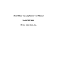
Step 4: Go to Options>Video Capture Filter …
Make sure the settings are set as follows:
Make sure auto is unchecked everywhere. The other parameters you may have to adjust these
depending on the lighting. AR works better in a well lit area, like the computer labs.
You want to keep the exposure as low as you can without the image becoming too dark. If you increase
exposure time, you will see that the image appears to slow down and blur at times. This makes tracking
more error prone. You may have to adjust this based on the lighting. Don’t try to use the Brightness
parameter to compensate for poor lighting. It will just make tracking worse.
Step 5: Hit Apply to save settings and then hit OK. Close AMCap
Step 6: Download camcalibandmarkers.zip and unzip it somewhere.
Step 7: Open Alvar.pdf. Print out page 9 - make sure to choose None for page scaling. Lay the
checkerboard on a flat surface. You want this to be as flat as possible. Tape may help.
Step 8: Open samplecamcalib.exe and point the camera at the checkerboard. In the console window you
should see some numbers print out like 1/100, 2/100 etc. Each time you see these numbers print,
it means that it has successfully taken a screenshot that will be used for calibration. If it can’t see
the checkerboard or you are at too close an angle to the checkerboard plane, it won’t take a
picture until you move the camera to a better position. Move the camera around slowly to that it
views the checkerboard pattern from many different directions. When it gets to 100/100, it will
put the results into calib.xml in the same directory. Close the samplecameracalib windows.
Note: calib.xml is the calibration file for your specific camera. You should not have to do this calibration
again if you don’t lose your calib.xml. By showing the camera this checkerboard of known
dimensions, the software calculated the unique camera parameters like lens distortion and focal
length.
Step 9: Now copy calib.xml into the GoblinXNAv3.4\tutorials\Tutorial8 - Optical Marker Tracking folder.
Part II: Try out AR in GoblinXNA
Step 1: In GoblinXNAv3.4\tutorials\Tutorial8 - Optical Marker Tracking you will find groundALVAR.pdf
and toolbarALVAR.pdf. Print these out with page scaling set to none. You will need a longer sheet
of paper for the groundALVAR.pdf. (Actually it will still work if choose ‘Shrink to Printable Area’,
but later GoblinXNA might think the camera is further away from the marker than it actually is.)
Step 2: Now open Tutorials.sln in GoblinXNAv3.4\tutorials\. Right click on tutorial 8 and Set As Startup
Project. Make sure useStaticImage is false:
// set this to false if you are going to use a webcam
bool useStaticImage = false;
Make sure your capture parameters are set to 60 FPS at 640x480 in the SetupMarkerTracking()
method:
else
{
captureDevice = new DirectShowCapture();
captureDevice.InitVideoCapture(0, FrameRate._60Hz, Resolution._640x480,
ImageFormat.R8G8B8_24, false);
}
Step3: Hit the green arrow. Now you should see some a cube and a sphere if you point your camera at
the ground marker.
Step 4: Play around with the ground and the toolbar markers and get a feel for moving them around at
different speeds and from different distances from the camera. Try moving the camera around
with the objects stationary. Cover parts of the ground marker up and see if you can get it to
disrupt the tracking.
Part III: Create a new marker for use in AR.
Step 1: Go to the command line (Start>Run>cmd). Navigate to the folder where you unzipped
camcalibandmarkers.zip.
Step 2: Type: samplemarkercreator 0 and press enter.
Step 3: If you look in the directory now, you should see MarkerData_0.png. Open it. Notice that this is
also one of the markers on one of the corners of the ground array. This is why we currently
shouldn’t use it. That is, it would confuse the tracking system to have two of these markers in
the same scene. We need to generate a new marker.
Step 4: Choose 4 numbers between 54 and 65535. For each number: type samplemarkercreator
yournumber into the command line and press enter. You should now see a
MarkerData_yournumber.png for each of the 4 your numbers.
Step 5: Open the SampleLayout.xml from the same directory. (Visual Studio works well to edit XML) Edit
the XML image parameters to point to your marker png files instead of the markers included.
Change the id parameters to match. Take note of the size in inches of your marker array
(width/pixelPerInch, height/pixelPerInch). In this case it is 8in x 8 in. Save the changes.
Step 6: Run MarkerLayout.exe. This should generate ALVARArrayFromXML.gif and
ALVARConfigFromXML.txt. Copy ALVARConfigFromXML.txt into your
GoblinXNAv3.4\tutorials\Tutorial8 - Optical Marker Tracking folder
Step 7: Open Microsoft Word or some other layout program (GIMP works for this too but is more
complicated) and insert the ALVARArrayFromXML.gif into the document. Right click on the
inserted image and click Size … Change it to the correct size you computed in Step 5 (8in x 8in).
Step 8: (Optional) Widen the margins of the document and center the marker.
Step 9: Print out the marker making sure not to rescale anything.
SampleLayout.xml Explained
Here are the main points you need to know about the XML file:
width/height - this is the size in pixels of the image produced. Keep in mind that each marker is
108x108 pixels. So if you wanted to put four markers in a column width would need to be GREATER
THAN 108 * 4. You need to keep some white border around the individual markers. This is necessary
for tracking.
pixelPerInch - this defines the actual size that the marker array should be when printed out. At
width=”400”, height =”400”, and pixelPerInch=”50”, the resulting gif should be printed out to be 8in x
8in.
center - this is the origin of the coordinate system of the marker. When you attach a model to the
marker in GoblinXNA, this is the position where the object will be drawn by default (you can change this
in GoblinXNA with a TransformNode that has the MarkerNode as a parent). If you set the center to be
width/2, height/2 as I have done in the example, the origin will be at the center of the marker.
upperLeftCorner - this defines where an individual marker appears within the resulting image.
Marker Design Tips
You will have to design new marker arrays for your final project.
1. Multiple markers in an array are typically better than a single marker. However, depending on the
constraints of your design, you might want to have one marker rather than four in an array. You must
adjust the xml file for this, as with any other marker array design.
2. There should always be white space around each individual marker. There is no answer as to how
much, but too little could confuse the tracking if the camera is far enough away.
3. For best results, your markers must be as flat as possible. Pasting them on a rigid surface like
cardboard is very helpful.
Part IV: Importing your marker into Goblin XNA
Step 1: Open Tutorials.sln in GoblinXNAv3.4\tutorials\
Step 2: Right click on Tutorial8 - Optical Marker Tracking in the Solution Explorer and click Add>Existing
Item... Change ‘Objects of type’ to ‘(*.*)’. Navigate to ALVARConfigFromXML.txt in your
GoblinXNAv3.4\tutorials\Tutorial8 - Optical Marker Tracking folder. Select it and click Add.
Step 3: You should now see ALVARConfigFromXML.txt just under ‘Content’ in the properties
window. Right click on it and select ‘Properties’. You should now see the properties window for it.
Step 4: Under ‘Copy to Directory’ select Copy if newer.
Part V: Track your marker and display a cylinder.
Step 1: Add MarkerNode cylinderMarkerNode; to the instance fields near the top of Tutorial8.cs.
You will see other MarkerNodes there.
Step 2: At the end of CreateObjects() add
ids = new int[4];
ids[0] = 50;
ids[1] = 51;
ids[2] = 52;
ids[3] = 53;
cylinderMarkerNode = new MarkerNode(scene.MarkerTracker,
"ALVARConfigFromXML.txt", ids);
Step 3: Remember the ids you used for you marker array? If not, look back at your SampleLayout.xml
file. Replace the ids above with your ids.
Step 4: Below that, create a cylinder and add it to the scene graph as follows.
GeometryNode cylinderNode = new GeometryNode("Cylinder");
cylinderNode.Model = new Cylinder(3,3,6,10);
cylinderNode.Material = sphereMaterial;
TransformNode cylinderTransNode = new TransformNode();
cylinderTransNode.Translation = new Vector3(0, 0, 3);
cylinderMarkerNode.AddChild(cylinderTransNode);
cylinderTransNode.AddChild(cylinderNode);
scene.RootNode.AddChild(cylinderMarkerNode);
In general you create a GeometryNode for the cylinder model and a TransformNode to define the
position/orientation/scale. You then add the TransformNode as a child to the MarkerNode, and the
GeometryNode as a child to the TransformNode. Then the MarkerNode is made a child of the scene root
node. Notice how I translated it up by its radius so it looks flush against the marker.
Step 5: Hit the green arrow and play with your new AR cylinder! Take a screenshot and save it as
newmarker.jpg
Part VI: What are the main limitations of AR?
Step 1: Write a list of 5 ways to break the illusion, disrupt tracking, etc.
Step 2: Describe two of the tracking errors that you saw and explain in detail how to how to reproduce
them (4-5 sentences).
Submit
Step 1: Zip the screenshot (Part V, Step 5) and the text file from part VI. Make sure all of your team
member’s names are in the text file.
Step 2: Submit through blackboard. It doesn’t matter who submits. You will all get credit.