1
AN ABSTRACT OF THE THESIS OF
Uday Banerjee for the degree of Master of Science in
Electrical & Computer Engineering presented on December 4, 2003.
Title: Hardware Encryption Using the MPC180 Security Co-Processor.
Abstract approved:
Cetin Kaya Koç
Hardware cryptography offers a reliable way to provide security for data that is
sent over networks. Security processors have taken the stage in the movement for
secure computing. Some of the more prominent security processors belong to the
S1 family created by Motorola. The primary goal of this thesis is to document and
test the performance of one of these processors, the MPC180, by executing efficient
code for standard cryptographic algorithms. The MPC180 is a network security coprocessor which is capable of performing on-the-fly encryption of all network data,
thus adding an extra layer of security. This processor is capable of performing intensive cryptographic computations, while offloading the burden of these computations
from the host processor, thus freeing up valuable resources on the host to perform
other functions. A real-time operating system (VxWorks) and its associated tools
(Tornado) were used to accurately examine and time the operation of the security
processor. The results are compared to other cryptographic hardware and software
implementations.
c
°
Copyright by Uday Banerjee
December 4, 2003
All rights reserved
Hardware Encryption
Using the
MPC180 Security Co-Processor
by
Uday Banerjee
A THESIS
submitted to
Oregon State University
in partial fulfillment of
the requirements for the
degree of
Master of Science
Presented December 4, 2003
Commencement June 2004
Master of Science thesis of Uday Banerjee presented on December 4, 2003
APPROVED:
Major Professor, representing Electrical & Computer Engineering
Director of the School of Electrical Engineering and Computer Science
Dean of the Graduate School
I understand that my thesis will become part of the permanent collection of Oregon
State University libraries. My signature below authorizes release of my thesis to any
reader upon request.
Uday Banerjee, Author
ACKNOWLEDGMENT
I would like to thank Dr. Koç for giving me the opportunity to work on this
interesting project. Dr. Koç’s discussions, directions and guidance helped me greatly
in accomplishing this work. I thank Dr. Tenca, who made sure that this project
received the necessary tools and software. I also thank Dr. Traylor for his support. I
greatly appreciate the help and discussion provided by my friends at the ISL: Gokay
Saldamli, Lo’ai Tawalbeh and Dana Zottola. I would also like to thank the community
at comp.os.vxworks for all their help. Finally, I am grateful for all the support my
family has given me during this project.
TABLE OF CONTENTS
Page
1.
Introduction . . . . . . . . . . . . . . . . . . . . . . . . . . . . . . . . . . . . . . . . . . . . . . . . . . . . . . .
1.1.
1.2.
2.
1
Motivation . . . . . . . . . . . . . . . . . . . . . . . . . . . . . . . . . . . . . . . . . . . . . . . . .
1
1.1.1. Cryptography . . . . . . . . . . . . . . . . . . . . . . . . . . . . . . . . . . . . . .
1.1.2. Embedded systems in today’s networks. . . . . . . . . . . . . .
1
1
The Motorola MPC180 security co-processor . . . . . . . . . . . . . . . .
2
1.2.1. Features . . . . . . . . . . . . . . . . . . . . . . . . . . . . . . . . . . . . . . . . . . . .
1.2.2. Architecture of the MPC180 . . . . . . . . . . . . . . . . . . . . . . . .
2
4
The development environment and tools (VxWorks and Tornado) . . 10
2.1.
VxWorks. . . . . . . . . . . . . . . . . . . . . . . . . . . . . . . . . . . . . . . . . . . . . . . . . . . 10
2.1.1. Introduction to VxWorks . . . . . . . . . . . . . . . . . . . . . . . . . . . 10
2.1.2. VxWorks RTOS Facilities: . . . . . . . . . . . . . . . . . . . . . . . . . . 12
2.1.3. Why VxWorks? . . . . . . . . . . . . . . . . . . . . . . . . . . . . . . . . . . . . . 15
2.2.
Tornado . . . . . . . . . . . . . . . . . . . . . . . . . . . . . . . . . . . . . . . . . . . . . . . . . . . 15
2.2.1. Introduction to Tornado . . . . . . . . . . . . . . . . . . . . . . . . . . . . 15
2.2.2. Tornado Tools . . . . . . . . . . . . . . . . . . . . . . . . . . . . . . . . . . . . . . 24
3.
4.
Cross-Development with Tornado and the ZPC860 . . . . . . . . . . . . . . . . . 29
3.1.
What exactly does cross-development mean . . . . . . . . . . . . . . . . . 29
3.2.
Basic operation of the system : A user perspective . . . . . . . . . . 30
3.3.
Procedure . . . . . . . . . . . . . . . . . . . . . . . . . . . . . . . . . . . . . . . . . . . . . . . . . . 30
3.4.
Embedded system programming with VxWorks and Tornado 33
Results and Timing Analysis . . . . . . . . . . . . . . . . . . . . . . . . . . . . . . . . . . . . . . . 40
4.1.
ARC Four Hardware Accelerator (AFHA) Module . . . . . . . . . . 40
4.2.
Public Key Hardware Accelerator (PKHA) Module . . . . . . . . . 43
TABLE OF CONTENTS (Continued)
Page
4.2.1. RSA Module . . . . . . . . . . . . . . . . . . . . . . . . . . . . . . . . . . . . . . . 44
4.2.2. ECC Module . . . . . . . . . . . . . . . . . . . . . . . . . . . . . . . . . . . . . . . 47
5.
4.3.
Random Number Generator (RNG) Module . . . . . . . . . . . . . . . . 50
4.4.
Message Digest Hardware Accelerator (MDHA) Module. . . . . 52
Discussion . . . . . . . . . . . . . . . . . . . . . . . . . . . . . . . . . . . . . . . . . . . . . . . . . . . . . . . . . 56
5.1.
Analysis . . . . . . . . . . . . . . . . . . . . . . . . . . . . . . . . . . . . . . . . . . . . . . . . . . . 56
5.2.
Conclusions . . . . . . . . . . . . . . . . . . . . . . . . . . . . . . . . . . . . . . . . . . . . . . . . 57
5.3.
Future work . . . . . . . . . . . . . . . . . . . . . . . . . . . . . . . . . . . . . . . . . . . . . . . . 58
BIBLIOGRAPHY . . . . . . . . . . . . . . . . . . . . . . . . . . . . . . . . . . . . . . . . . . . . . . . . . . . . . . . . . . . 59
LIST OF FIGURES
Figure
Page
1
Architecture of the MPC180 security co-processor. . . . . . . . . . . . . . . . . . .
5
2
Real-time operating systems. . . . . . . . . . . . . . . . . . . . . . . . . . . . . . . . . . . . . . . . 11
3
The real-time operating system kernel. . . . . . . . . . . . . . . . . . . . . . . . . . . . . . . 12
4
The host side of the Tornado environment . . . . . . . . . . . . . . . . . . . . . . . . . . 16
5
The target side of the Tornado environment . . . . . . . . . . . . . . . . . . . . . . . . . 20
6
Tornado’s Target Server.. . . . . . . . . . . . . . . . . . . . . . . . . . . . . . . . . . . . . . . . . . . . 20
7
Tornado’s Registry. . . . . . . . . . . . . . . . . . . . . . . . . . . . . . . . . . . . . . . . . . . . . . . . . . 23
8
Tornado’s built-in simulator. . . . . . . . . . . . . . . . . . . . . . . . . . . . . . . . . . . . . . . . . 25
9
Tornado’s project management facility. . . . . . . . . . . . . . . . . . . . . . . . . . . . . . 26
10
Tornado’s WindView facility. . . . . . . . . . . . . . . . . . . . . . . . . . . . . . . . . . . . . . . . 28
11
Hyperterminal startup screen. . . . . . . . . . . . . . . . . . . . . . . . . . . . . . . . . . . . . . . 31
12
VxWorks ready screen. . . . . . . . . . . . . . . . . . . . . . . . . . . . . . . . . . . . . . . . . . . . . . 33
13
Tornado startup screen. . . . . . . . . . . . . . . . . . . . . . . . . . . . . . . . . . . . . . . . . . . . . 37
14
Tornado Application Creation Wizard. . . . . . . . . . . . . . . . . . . . . . . . . . . . . . . 38
15
Tornado Application Creation Wizard Step 2. . . . . . . . . . . . . . . . . . . . . . . . 39
16
WindView timing graph for RC4. . . . . . . . . . . . . . . . . . . . . . . . . . . . . . . . . . . . 42
LIST OF TABLES
Table
Page
1
WindView timing for RC4. . . . . . . . . . . . . . . . . . . . . . . . . . . . . . . . . . . . . . . . . . 41
2
WindView timing for RSA exponentiation. . . . . . . . . . . . . . . . . . . . . . . . . . . 44
3
WindView timing for RSA modular addition. . . . . . . . . . . . . . . . . . . . . . . . 45
4
WindView timing for RSA modular subtraction. . . . . . . . . . . . . . . . . . . . . 46
5
WindView timing for RSA modular multiplication. . . . . . . . . . . . . . . . . . . 47
6
WindView timing for ECC addition in F(p). . . . . . . . . . . . . . . . . . . . . . . . . 49
7
WindView timing for ECC addition in F(2n). . . . . . . . . . . . . . . . . . . . . . . . 49
8
WindView timing for ECC point doubling in F(p). . . . . . . . . . . . . . . . . . . 50
9
WindView timing for ECC point doubling in F (2ˆn). . . . . . . . . . . . . . . . . 51
10
WindView timing for 32-bit RNG generation. . . . . . . . . . . . . . . . . . . . . . . . 51
11
WindView timing for 100 blocks of 32-bit RNG generation.. . . . . . . . . . 52
12
WindView timing for SHA-1. . . . . . . . . . . . . . . . . . . . . . . . . . . . . . . . . . . . . . . . 53
13
WindView timing for MD5. . . . . . . . . . . . . . . . . . . . . . . . . . . . . . . . . . . . . . . . . . 54
14
Run Time Formulae. . . . . . . . . . . . . . . . . . . . . . . . . . . . . . . . . . . . . . . . . . . . . . . . 55
HARDWARE ENCRYPTION USING THE MPC180 SECURITY
CO-PROCESSOR
1.
Introduction
1.1. Motivation
1.1.1. Cryptography
The security and integrity of data that is sent over today’s networks is of paramount
importance. Applications and services that use networks to send and receive data
range from banks, to stock market data, to military applications, and to common
e-mail. If proper precautions are not taken, every bit of data that is sent over the
internet is susceptible to malicious activity. The art and science of cryptography has
been around for many hundreds of years, and is being used today to provide a layer
of security for information that needs to be protected. This thesis deals with how
embedded systems are being used to provide cryptographic security to network data.
The focus of this thesis is the MPC180, which is a network security co-processor that
is designed to execute computationally intense algorithms generally associated with
cryptography.
1.1.2. Embedded systems in today’s networks
An embedded system is a combination of hardware and software, designed to perform a specific function [1]. Embedded systems are becoming the new frontier for
secure computing. These systems are now being used to provide security for cellular
and wireless data, on-demand video, and internet traffic, to name a few areas [2]. The
real-time nature of embedded system processing presents great advantages to the nature of applications mentioned above. Other advantages that embedded systems offer
2
over traditional systems are the secure storage of secret information (such as private
keys), and higher speeds of execution.
1.2. The Motorola MPC180 security co-processor
Data security is a critical concept in today’s world. Cryptography is essential to
securing data and communications, and is extensively used in electronic commerce,
wireless communication, and banking. The rapid miniaturization of processing power
has led to increasingly smaller devices that perform custom duties, and in our case,
cryptography. This thesis deals with such a device, called the MPC180 security coprocessor, developed by Motorola, Inc. This network security co-processor is designed
to perform fast, on-the-fly encryption/decryption of data, thus adding security to data
that is to be sent over a network. The following is a brief summary of the features of
the MPC180 security co-processor [3].
1.2.1. Features
The MPC180 is based on Motorola’s MPC8xx or MPC826x family of POWERQUICC communicator processors. The MPC180 can handle intense cryptographic
applications and offloads the computational burden associated with them from the
host processor. The MPC180 is designed to support all the algorithms associated
with IPSEC, IKE, and SSL/TLS. This processor is capable of providing elliptic curve
cryptography support for WLTS/WAP in wireless applications.
The MPC180 has the following features [3]:
• PKEU (Public Key Execution Unit):
- RSA and Diffie-Helman
- Signature time of 32ms (1024 bit)
3
- 10 IKE handshakes per second
- Programmable field size of 80 - 2048 bits
- Elliptic Curve cryptography in either F (2m ) or F (p)
- 155 bit signature time of 11ms
- 30 IKE hand-shakes per second.
- Programmable field size of 55 - 511 bits
• DEU (DES Execution Unit):
- 3DES-HMAC-SHA-1 performance upto 15 Mbps.
- ECB and CBC modes for both DES/3DES
- Support for 2 key and 3 key 3DES
• AFEU (Arc Four Execution Unit):
- RC4 up to 20 Mbps
- Programmable key size from 40- to 128-bits
• MAU (Message Authentication Unit):
- SHA-1 with 160 bit message digest
- MD5 performance 128 bit message digest
- HMAC with either algorithm
• RNG (Random Number Generator):
- Supplies upto 160 bit strings at 5Mbps data rate
• Software and Development Support
- VxWorks drivers
- Sample drivers
- SBC8260C development board and board support package from WindRiver.
4
• Packaged in a low-cost 100-pin LQFP package.
• 1.8V VDD, 3.3V I/O
• Low Power Dissipation at 0.6W
• Input and Output buffer (4 Kbits each)
• Glueless interface to MPC8xx system or MPC826x local bus (50 MHz and 60
MHz)
• DMA hardware handshaking signals for use with the MPC826x
1.2.2. Architecture of the MPC180
This section outlines the architectural features of the MPC180 security coprocessor [3]. For the purpose of this study, the MPC180 is interfaced to the ZPC860
processor card, which has the following features [4]:
• 32 MB SDRAM SODIMM
• Five board to board connectors
• 2 MB Flash memory
• Built-in RS-232 serial port
• Built-in ethernet port
The MPC180 itself is meant to integrate into any system that supports Motorola’s
integrated communication processors [3]. The MPC180 works such that it resides in
the host processor’s memory map. Any application that wishes to use a cryptographic
routine simply needs to write to a specific memory location and read the result back
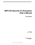
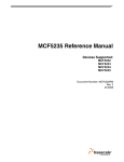
from another location. Figure 1 shows the functional block diagram of the MPC180’s
internal architecture [3].
5
FIGURE 1: Architecture of the MPC180 security co-processor.
The MPC180 interfaces to Motorola’s MPC8xx system bus or the MPC8260’s local
bus. For the purposes of this thesis, the MPC180 was interfaced to the ZPC860’s
system bus through the External Bus Interface (EBI), which performs the following
functions:
• Translates the processor core bus timing into a simple read/write interface for
the execution units
• Decodes the memory address in order to select the appropriate execution unit
The EBI contains two First In First Out (FIFOs) registers, one input and one
output, of size 4096 bits each, which are used to maximize throughput and make
it easier on the host processor’s data management responsibilities. The MPC180
manages data transfer between the FIFOs and the execution units (EU) with no
intervention necessary on the host processor’s part.
The MPC180 operates in one of two modes,
• Open address mode, where the host processor can write directly to the MPC180
address map
6
• FIFO mode, where the MPC180 accepts data transfers upto 4 kilobits to and
from the FIFOs.
There are five execution units on the MPC180:
• PKEU (Public Key Execution Unit), which handles the RSA and ECC computations
• DEU (DES Execution Unit), which handles DES and 3DES computations in
both CBC and ECB modes
• MDEU (Message Digest Execution Unit), which handles the SHA-1 and MD-4/5
computations
• AFEU (Arc Four Execution Unit), which handles the RC4 computations: and
• RNG (Random Number Generator), which generates 32-bit random numbers
These EUs are connected to the FIFOs and the controller via multiplexers. The
EBI, mentioned above, is responsible for selecting the necessary execution unit.
Once the appropriate EU has been selected, it receives the input data from the input
FIFO, processes the data, and returns the output to the output FIFO. This output
data is then written back to a specific address in the host PC’s memory map.
A description of the individual execution units is given below.
• Public Key Hardware Accelerator (PKHA) Module
The PKEU supports elliptic curve cryptography and Rivest, Shamir and
Adleman [5] algorithms.
Elliptic curve is supported in both F (2ˆm)
(polynomial-basis) and F (p) modes.
7
The mpc180Pkha module performs advanced mathematical functions to support RSA and ECC public key cryptographic algorithms. The PKHA module
comprises of three sub-modules. The names of the sub-modules are,
– mpc180PkhaUtil
– mpc180PkhaEcc
– mpc180PkhaRsa
The first of the sub-modules, the mpc180PkhaUtil, executes the following functions:
– Load and read large number registers
– Load and read the modulus size
– Clear the register memory, and perform supporting calculations
The second sub-module, the mpc180PkhaEcc, is used to perform elliptic curve
cryptography. Elliptic curve cryptography is supported in both F (2ˆn) and
F (p). The ECC module allows for two levels of operations. The first is high
level, and executes elliptic curve point multiplication using either projective or
affine co-ordinates. The second level allows for the execution of elliptic curve
additions and point doubles. These applications that run these operations are
required to work with projective co-ordinates with all the inputs and outputs
being in the Montgomery residue system.
The third sub-module, the mpc180PkhaRsa is used to perform modular arithmetic, like the RSA algorithm, DSA algorithm and Diffie-Hellman. Again, the
computations are classified into two levels. The first level (high-level) performs
modular exponentiation (XˆY mod N ), and the second level of computation involves modular addition, subtraction, and multiplication. It may be noted that
the minimum number of digits that the RSA and ECC routines can work with
are 128 and 32 respectively.
8
• DES Hardware Accelerator Module
The DEU is used to perform bulk data encryption and decryption in accordance
with the Data Encryption Standard algorithm. The DEU also computes Triple
DES. The MPC180E supports two key (K1 = K3) or three key 3DES. The DEU
operates by permuting 64-bit data blocks with a shared 56-bit session key and
an initialization vector. The MPC180E supports two modes of Initialization
Vector operation, namely CBC or Cipher Block Chaining mode, and ECB or
Electronic Code Book mode.
• Arc Four Hardware Accelerator (AFHA) Module
The AFHA module performs symmetric encryption and decryption compatible
with RSA’s RC4 stream cipher, where a byte of plaintext is encrypted with a
key to produce a byte of ciphertext. The AFHA module supports key ranges
from 40 bits to 128 bits. The mpc180Afha module uses two routines to perform
encryption/decryption:
– mpc180AfhaSetKey(): This is used to set the key used for the encryption/decryption
– mpc180AfhaProcess(): This routine is used to perform the RC4 encryption/decryption
The mpc180Afha module is very versatile; it is able to easily perform encryption
context switching. This means that the module is capable of halting a current
execution, and allowing the encryption of another message with a new key.
This feature is very useful for applications where a subsequent encryption has
a higher priority and needs to be processed immediately.
9
• Message Digest Hardware Accelerator (MDHA) Module
The mpc180Mdha message digest hardware accelerator module is capable of
performing hash algorithms like the SHA-1 and MD5. It is also capable of
generating an HMAC, which can be built upon an existing message digest calculation. This unit takes 16 32-bit words as input, runs them through the
specific algorithm, and produces a hashed message of 160 bits for SHA-1 or
128 bits for the MD4/MD5 algorithm. This EU is also capable of generating a
HMAC (Hashed Message Authentication Code) built upon the aforementioned
hash functions.
The basic routine used in these calculations is mpc180Hash(). The arguments
of this function are algorithm, input buffer, length of message, output buffer.
The ’algorithm’ parameter specifies which algorithm this function must use to
generate the hash, and possible values are SHA-1 and MD5. The output buffer
must be able to hold 16 bytes for MD5 and 20 bytes for SHA-1.
• The Random Number Generator (RNG) is designed to produce 32-bit random
numbers. The random numbers are tested for compliance with the Federal
Information Processing Standards (FIPS-140) guidelines for randomness and
non-determinism. The RNG is a valuable resource to the MPC180 because of
the fact that it is highly desirable to have a physically private random number
generator, in order to keep secret keys confidential. These keys can even be
hidden from higher level application code.
10
2.
The development environment and tools (VxWorks
and Tornado)
2.1. VxWorks
2.1.1. Introduction to VxWorks
Real-time operating systems are developed to perform a specialized set of tasks,
and have a strict set of requirements for their operating systems [6]. VxWorks is
one of today’s most widely implemented real-time operating systems. VxWorks can
make scheduling guarantees that normal operating systems cannot. VxWorks and
Tornado, a set of tools used for application development, are an integral part of this
thesis. Real-time operation is a very important part of this thesis, and this is why
VxWorks, one of the popular real time operating systems (RTOS), and its associated
Integrated Development Environment (IDE), Tornado, have been used.
The reason why a real-time operating system is used is because traditional operating
systems like Windows and UNIX are ill suited to handle any real-time applications.
On the other hand, operating systems like VxWorks, built especially for handling
real-time processes, are poor performers when it comes to non real-time application
development. VxWorks can operate in tandem with either UNIX or Windows so
that each type of operating system (RTOS and non-RTOS) can do what it does
best. This means that VxWorks would handle the time-critical aspects while the host
operating system would handle the program development and non real-time aspect
of the application. VxWorks is very flexible in that it lets a user customize it to
include the features that the application requires. For example, VxWorks allows the
user to configure it such that features like networking can be added to speed up the
development cycle, and the same can be excluded in the post-production phase. Thus
we see that a real-time operating system has significant advantages over traditional
11
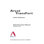
FIGURE 2: Real-time operating systems.
operating systems when it comes to working with sensitive timing requirements. The
basic requirements and capabilities of VxWorks are summarized below:
• Real-time operating systems should always respond to an event in a guaranteed
amount of time, which is in the order of microseconds or nanoseconds. This is
the essence of real-time.
• Real-time operating systems are capable of working with a minimal set of resources, like memory.
• A real-time operating system is rugged and will be resilient to situations that
would otherwise cause a non-real-time operating system to crash.
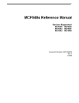
Figure 2 shows how a real-time operating system fits into the scheme of things,
with the development tools running on a host computer, and VxWorks running on
the development board.
The real-time operating system will run on the hardware target, while the development tools run on the host computer. The network functions as the interconnection
between the host and the target. It provides facilities like file transfers between the
host and the target, and has the ability to boot the board over the network. The
12
FIGURE 3: The real-time operating system kernel.
development tools communicate with the real-time operating system and gather information that can be analyzed.
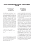
Figure 3 shows the functional structure of a real-time operating system. It comprises
of a multitasking kernel, which performs functions like real-time scheduling, intertask
communication and mutual exclusion. This kernel is linked to the file systems, device
drivers, I/O systems, and the network stack. More information about the various
facilities offered by VxWorks are described below. The subsequent sections will deal
with how VxWorks is used in real-time development.
2.1.2. VxWorks RTOS Facilities:
Real-time systems, as mentioned above, are designed to work in conjunction with
standard operating systems. The following material will provide a brief overview of
the salient facilities and tools provided by VxWorks [7].
13
Facilities:
• Input/Output System: VxWorks comprises a speedy, stable and flexible I/O
system. It includes several drivers that encapsulate key input/output mechanisms, like keyboard driver, RAM Disk driver, display driver, etc.
• High Performance Real-time kernel facilities: VxWorks’ kernel, called ’Wind’
is a multi-tasking kernel, and its key features are real-time scheduling, mutual exclusion (semaphores), and intertask communication. These features are
what distinguish the real-time operating system from the non-real-time operating system. The kernel is very fast and engages in preemptive priority based
scheduling of its tasks. This kernel belongs to what we would call a micro-kernel
architecture, for it is small and highly configurable.
• Fast file systems: VxWorks employs custom tailored file systems that are designed for real-time operation. The file system formats used are compatible
with DOS, RT-11, SCSI, CD-ROM, and “raw-disk” file system. Overall, these
fast file systems are critical to the operations of a RTOS, where timing is of the
essence.
• C++ support: VxWorks ships with a variant of GNU’s GCC C/C++ compiler.
There are other compilers available, like the Diab compiler, which is Wind
River’s own compiler.
• Target Resident Tools: A complete set of tools used for development are present
on the host machine, thus conserving target memory and resources, but there is
also a target resident shell, a symbol table, and a module loader/unloader that
can be configured into the target OS as required.
• Evaluation Tools and Utility libraries: Performance evaluation tools, that include utilities to display processor utilization percentages by a particular task,
and an execution timer are present. VxWorks includes a comprehensive set
14
of utilities, like timers, interrupt handling, memory allocation, and ANSI C
libraries.
• Network Facilities: VxWorks network facilities are compatible with standard
internet protocols. Thus, setting up communications between the host and the
target using regular equipment like routers is an extremely simple process.
• Board Support Packages: A board support package is the board specific part
of VxWorks. It contains initialization code for the hardware as well as device
drivers for included components on the board like serial, parallel and ethernet
ports, SCSI and IDE controllers, etc. VxWorks supports a large number of
boards, and thus provides an easy development process.
• Virtual Memory: VxWorks includes virtual memory management for boards
that require this feature.
• Shared Memory Objects: In the case of a multi-processing environment, Vxworks has features that enable it to share resources like memory and semaphores
between different processors.
• The VxWorks Simulator: The VxWorks simulator, VxSim, simulates a VxWorks
target in order to test the software. Tornado’s tools are designed to work closely
with VxSim in order to analyze and test the software effectively.
• Utility libraries: The following are the utility libraries provided with VxWorks.
1. Interrupt handling
2. Watchdog timers
3. Message logging
4. Memory allocation
5. String formatting and scanning
6. ANSI C libraries
15
2.1.3. Why VxWorks?
There are other real-time operating systems available from various companies like
QNX, LynxOS, Windows-CE, Integrity, and ThreadX. But it so happens that while
certain companies’ products, like Green Hills’ RTOS products, have been gaining a
lot of popularity, VxWorks probably is still the most widely used real-time operating
system (RTOS) in the embedded industry. VxWorks has built a good reputation for
itself owing to its flexibility, compatibility and scalability. Furthermore, WindRiver
Systems provides excellent technical support. Due to these advantages, the MPC180’s
board support package was written for use with VxWorks. A detailed section on the
procedures involved in actually running VxWorks on a board is presented in Chapter
3.
2.2. Tornado
Tornado is a development environment designed for use with VxWorks. One can
call it a suite of software and tools that are designed to interface with VxWorks and
provide an efficient platform for cross development.
2.2.1. Introduction to Tornado
Tornado from WindRiver Systems is a development environment for VxWorks.
While VxWorks runs on the development board, Tornado and it’s tools run on the
host computer, communicating with VxWorks, and facilitating exchange and analysis
of data. Tornado comprises of three main components. They are
1. VxWorks
2. Tools for application development
16
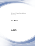
FIGURE 4: The host side of the Tornado environment
3. IDE (Integrated Development Environment)
The Tornado Host-Target interface serves as the connection between the host and
target environments. This is explained in detail later in this section.
The Tornado IDE is a comprehensive suite of software and tools used for real time
application development. The salient features of the IDE are as follows [8]:
• Integrated source code editor
• Integrated C/C++ compilers1
1
Most commonly GNU’s gcc compiler[9]
17
• CrossWind, a GUI based debugger
• WindSh, a C based command shell
• Browser, which is a visual monitoring system
• VxSim, a simulator program used to simulate the behavior of the target
• Project management facility
• WindView, a timing and analysis tool (software and logic analyzer)
An in depth explanation of these tools is given in section 2.2.2. Figures 4 and 5
(adapted from [8]) show the Tornado Development Environment’s structure.
Figure 4 shows the host side of the environment, while figure 5 shows the target
side of the environment.
Tornado’s File Structure:
Tornado/
Root Directory
docs/
Online documentation
host/
Location of the host resident tools
SETUP/
Tornado setup program
share/
Protocol definitions shared by host
and target software
target/
config/
all/
System configuration information
bsp name/
files related to a particular board
h/
Header files
lib
Processor independent libraries
and modules
src/
C source code files
18
config/ Source for VxWorks supplied modules
.wind/
demo/
WindRiver supplied demos
drv/
Device drivers
usr/
User changeable code
Files used to customize Tornado tools
Tornado’s file structure on the host computer is shown above, in order to give the
reader a general idea of how Tornado’s files are organized.
The Tornado Host-Target interface is the connection between Tornado’s tools described above and the VxWorks environment that is running on the board. This
interface comprises of three main components, namely, the Target Agent, the Target
Server and the Tornado Registry. Each of these are explained in detail below.
• Target Agent: All Tornado tools are represented by the target agent on the target. The target agent is a compact implementation of the core services necessary
to respond to requests from the Tornado tools. The agent responds to requests
transmitted by the target server, and replies with the results. These requests
include memory transactions, notification services for breakpoints and other
target events, virtual I/O support, and task control. The agent synthesizes two
modes of target control: task mode (addressing the target at application level),
and system mode (system-wide control, including Interrupt Service Routine debugging). The agent can execute in either mode, and switches between them
on demand. The agent is independent of the run-time operating system, interfacing with run-time services indirectly so that it can take advantage of kernel
features when they are present, but without requiring them. The agents driver
interface is also independent of the run-time, avoiding the VxWorks I/O system. Drivers for the agent are raw drivers that can operate in either a polling or
an interrupt-driven mode. A polling driver is required to support system-level
19
breakpoints. Run-time independence means that the target agent can execute
before the kernel is running. This feature is valuable for the early stages of
porting VxWorks to a new target platform. A key function of the agent is to
service the requests of the host-resident object-module loader. If the agent is
linked into the run-time and stored in ROM, the target server automatically
initializes the symbol table from the host-resident image of the target run-time
system as it starts. From this point on, all downloads are incremental in nature,
greatly reducing download time.
The agent itself is scalable; you can choose what features to include or exclude.
This permits the creation of final-production configurations that still allow field
testing, even when very little memory can be dedicated to activities beyond the
applications purpose.
• Target Server: The target server is a component of Tornado that runs on the
host computer, and its function is to connect Tornado’s tools to the target
agent. The target agent is a very condensed collection of services which run
on the target while providing information to Tornado’s tools. There is one
target server that runs on the host computer for every target that the host
is attached to. The tools that run on the host request information from the
target via the target server. The target server communicates with the target
agent and requests from it information that was solicited by the tools. The
target server also manages the connection between the host and the target.
A useful feature of the target server is that it caches target information like
memory addresses, so that in case a tool requests a memory read from the
target, there is no need for the target server to even perform a request for
target memory access. When the target server runs, its name is linked with
the name of the host machine and the name of the target. For example, if
the name of the host machine is “izmir” and that of the target is zpc860, the
20
FIGURE 5: The target side of the Tornado environment
FIGURE 6: Tornado’s Target Server.
21
target server would be named “zpc860@izmir”. Figure 6 shows a screenshot of
a target server in action. The target server keeps a record of the symbol table
for the target executable on the host computer. This symbol table is built by
the target server from a file known as the “core files and symbols”, which can be
selected from the drop-down menu called “Target Server Configuration”. From
several users experiences, as reported in [10], synchronization problems were
rectified by specifying the “vxWorks” file in the “core file and symbols” option,
instead of using the “vxWorks rom” file. It is also suggested here that the
option “synchronize host/target symbol table” is selected in the target server
configuration.2
The target server could also operate on a different computer from which the
Tornado tools reside. The tools need to have network access to the remote
target server by some means in order to allow them to communicate with the
target. The target server needs to be configured with the following parameters:
– Target Server Name: This is what the target server will be called. Upon
choosing the option “Add description to menu”, this name will be available
for selection in the “Tools → Target Server” menu.
– Target Server Properties: The following are listed under this option:
1. Authorizations: Option used to restrict users access to the target
server. This option allows one to specify the location of an ‘authorization file’, which contains the names of authorized users. This file
can be found in “$WIND BASE/.wind/userlock”.
2. Back End: Allows the user to specify which back end is to be used to
connect to the target. The back end which needs to be used in the case
of hardware targets is “wdbrpc”, as specified in [8]. For a complete
2
One can refer to [10] for arguably one the most comprehensive “frequently asked questions” list
compiled on VxWorks/Tornado.
22
list of options, one can refer to Tornado’s “Help menu → Manuals
Contents → Tornado Reference → Tornado Tools” for “tgtsvr.exe”.
3. Core Files and Symbols: This option allows the user to specify the
location of the “core file”. The core file is used by the target server
to compute the symbol table for the target executable. This option
also allows you to synchronize the host and target symbol tables. This
will resolve any synchronization problems that may arise when the
target server tries to connect to the target. An example of a “Core
files and symbols” error is “The target system is not initialized yet.
Can’t proceed” [10].
4. Memory Cache Size: This option lets the user specify the cache size.
This can either be set to the default value (1 MB), or a user defined
value.
5. Target Server File System: This option allows the user to enable the
use of the Target Server File System.
6. Console and Redirection: This option allows the output to be redirected to the console.
7. Logging: This allows the creation of a log file.
8. Miscellaneous: This option allows the use of “portmapper”, in order
to ensure compatibility with Tornado 1.0.
– Target Name/IP Address: Specifies the target name or IP Address of the
target. The target server uses this value to connect to the target over the
network.
The target server can also be executed from the command line using “tgtsvr.exe”.
The command used in this thesis was:
“Command
prompt>tgtsvr.exe 192.168.2.15 -n 860 -V -B wdbrpc -R c: -RW”. The options
are briefly explained below.
23
FIGURE 7: Tornado’s Registry.
1. -n server name: specifies an alternate name for the target server. In this
thesis, the server name was “mpc860”.
2. -V: This activates the Verbose mode where the target server displays
information and error messages on the designated output.
3. -B backend name: Specifies the name of the back end used to communicate with the target agent. In this case the back end used was “wdbrpc”.
4. -R root: Specifies the root directory of the host file system.
5. -RW: Grants read/write privileges to the target processes over certain
host files.
24
• Tornado Registry: The registry is a service that maintains a database of target
servers, boards and RPC port numbers in the cross development system. The
registry facilitates the Tornado tools to connect to the target server. The registry keeps track of each individual target server by its name, which is in the
form of a unique identifier (e.g., “wtxregd@izmir”). Just like the target server,
the registry need not run on the host computer, but it should have network
access to the host in order for it to function properly. There can be more than
one instance of a registry that is running on the host at any given time, but it
is recommended that only one instance of the registry be run at a time to allow
for unhindered access to the target by the tools [8]. Figure 7 shows a Tornado
Registry in operation.
2.2.2. Tornado Tools
The Tornado Integrated Development Environment (IDE) is a comprehensive suite
of software and tools used for real time application development. The salient features
of the IDE are as follows [8]:
• Integrated source code editor: Tornado ships with an integrated source code
editor that performs standard functions like C/C++ syntax color highlighting.
The editor tracks execution of the code and is integrated with the debugger and
the project management facility.
• Integrated C/C++ compilers: Tornado includes a standard C/C++ compiler. 3
• CrossWind : CrossWind is a Graphic User Interface (GUI) based debugger based
on the GNU source level debugger. CrossWind can be used to perform tasks
like debugging on the target, attach to existing tasks, view application code,
and use debugging features at both the application and system levels.
3
Most commonly GNU’s gcc compiler[8, 9]
25
FIGURE 8: Tornado’s built-in simulator.
• WindSh: WindSh is a C based command shell that runs on the host. The shell
also supports C++ and includes a Tcl (Tool command language) interpreter.
The shell is very much like any UNIX shell, in that it can be used to navigate,
call program routines and functions, examine and modify memory. The shell
maintains a history of commands used and this can be accessed by pressing the
“Esc” key and the “J” or “K” keys. The shell can also be used to redirect input
and output.
• Browser : The Browser is a visual monitoring system used to monitor the state
of a target. Some of its displays include:
– Active task summaries
– CPU usage
– Memory usage and allocation
– Summary of modules linked to the run time system
– Semaphores, watchdog timers and message queues
26
FIGURE 9: Tornado’s project management facility.
• VxSim: VxSim is a simulator program used to simulate the behavior of the
target. It is essentially VxWorks ported to the host system, in order to simulate
a target’s behavior. A screenshot of the simulator is shown in figure 8.
• Project management facility: Tornado comes with a complete project management facility, which one can use to customize the project structure and content.
The project facility gives the user a graphical method of working with VxWorks
and the build environment. There are three tabs in the project facility, as shown
in figure 9.
1. Files: This window allows the user to add/delete files, access the code of
a program that is included in the project, calculate dependencies in the
code, build the VxWorks images and projects, and download the object
files on to the target.
2. VxWorks: This tab shows the user all the components that have been
included in the project, like operating system components, C/C++ components, and network components. In this tab, users can include and ex-
27
clude components, and can resolve any potential conflicts with the project
facility’s help. Users can also build VxWorks from this tab.
3. Builds: This tab shows the user the specifications of the build the project
is using. Double clicking on the build shown will bring up a dialog box that
shows specifications about the ToolChain, BSP (Board Support Package),
C/C++ compiler, rules, macros, assembler, linker, link order and rules.
Everything but the ToolChain and the BSP settings, can be modified in
this dialog box.
• WindView : WindView is a Tornado tool that provides the function of a run-time
analysis tool. WindView monitors the target system and logs critical information like timing, events (user defined or otherwise) and task state transitions.
User defined events, set with the “wvEvent()” function can be referenced in the
corresponding WindView output in order to accurately determine timing. This
method has been used in this thesis to time certain functions during run time.
A screenshot of a WindView output is shown in figure 10.
The subsequent chapter deals with cross development on the VxWorks/Tornado
system.
28
FIGURE 10: Tornado’s WindView facility.
29
3.
Cross-Development with Tornado and the ZPC860
3.1. What exactly does cross-development mean
Cross-Development, in the context of real-time application development involves
two connected systems, which are completely different platforms, but co-operate to
facilitate real-time application development. Real-time application development requires features from both traditional real-time operating systems (such as accuracy,
real-time operation, etc.) as well as features from non real-time operating systems
such as UNIX and Windows (such as processing power, memory capacity, etc.).
It makes sense to utilize the features of both the types of operating systems in
order to successfully develop real-time applications. Thus, the RTOS would handle
important real-time tasks, while the regular operating system would handle tasks such
as program development.
For instance, consider the systems involved in this thesis. The ’host’ system was
a personal computer (pc) running Windows(TM) 2000, and the ’target’ board was
a PowerPC. These boards were connected via a serial interface as well as through
the network. During application development, the Tornado tools like WindShell and
WindView would run on the host, while VxWorks system tasks would run on the
target.
This setup provides the development of the application with many benefits. Some
of these advantages are detailed below:
• Powerful resources (memory, processing power) of the host system can be utilized
• Scaling and customization of the application are easily possible
• Testing and debugging are taken care of by Tornado’s tools running on the host
Tornado ensures that there is minimal intrusion upon the target during application
development by segregating the development facilities on the host. Tornado also keeps
30
the run-time facilities as independent as possible from the development environment,
thus ensuring as little a difference as possible between the target system during actual
development and the target system after development.
The following section discusses the cross-development experience in relation to this
thesis from a user’s perspective. It seeks to explain the steps involved in going through
the actual cross-development cycle. There are many details that need to be attended
to during this process (see Section 2.5 of [8] for a comprehensive treatise on this topic).
3.2. Basic operation of the system : A user perspective
This section describes the steps involved in cross-development with the VxWorks/Tornado system. As explained above, cross-development involves two systems
that work together in a co-operative fashion. In this project, the host system was
a personal computer running Windows 2000, and the target board was the ZPC860
board (containing the MPC180 processor). The two systems were connected to each
other via a serial cable as well as over the network via an ethernet cable.
The board comes with a set of programs, called the Board Support Package (BSP).
The BSP is essentially the hardware-specific part of VxWorks code. The BSP performs board-specific functions like hardware initialization, memory mapping and interrupt handling [11]. The BSP acts like an interface between the VxWorks kernel
and the host based tools. The final procedure used for cross development is detailed
in the following section.
3.3. Procedure
1. Turn on the FTP server (supplied with Tornado) and give access to the user
with a username and password. This username and password will be used later
31
FIGURE 11: Hyperterminal startup screen.
by the board to log into the host computer and download the “vxWorks” image
that it needs to boot from the host.
2. The board is connected to the host computer via two interfaces:
• A serial port connection, and
• An ethernet connection, using a router or any standard networking device.
Upon powering up the target, the user must start Hyperterminal (a version
of Wind River’s hyperterminal is provided with Tornado), and connect to the
target using either COM1 or COM2. The terminal window is shown in figure 11.
3. The user is given an 8-second time interval to interrupt the board from loading
the VxWorks image from the location specified in the configuration. Since the
board comes with a pre-set configuration, it must be changed to reflect current
32
parameters. To boot up, the board uses pre-defined settings. These settings
can be displayed in the hyperterminal window by typing “p” at the “[VxWorks
boot]:” prompt. One can change these settings by typing in “c” at the prompt.
The common parameters are:
• file: This setting is very important because the board searches for the
VxWorks file on the host system at the location specified by this parameter.
If the file is not present there, the board will display an error and fail to
boot (for example: “C:’T́ornado’t́arget’ćonfig’ḿpc860’v́xWorks”).
• host name: This is to help identify the host machine on the network (for
example: “Izmir”).
• inet on ethernet: This is the IP address of the board, and it must be set
properly with a valid value before the board tries to boot.
• host inet: This is the IP address of the host machine. The board tries to
connect to this IP address over the network before loading the VxWorks
file specified in the “file” parameter.
• gateway inet: This is the IP address of the gateway computer, and need be
used only if the target and the host are not on the same subnet. If the host
and target are not on the same subnet, it is recommended that the user
first set the subnet mask of the board in the “inet on ethernet” parameter
as “xxx.xxx.xxx.xxx:0xfffffe00”, which represents the IP address, followed
by the sample subnet of “255.255.254.0”.
4. Once the desired parameters have been set, the “@” command is used to boot
the board with the current configuration. At this time, the board searches for
the VxWorks image on the host machine as specified in the “file” parameter.
Provided all the network settings are correct, the board then downloads the
VxWorks image onto its memory and loads up the VxWorks real-time operating
system. The system displays a message that says something like “WDB Ready”.
33
FIGURE 12: VxWorks ready screen.
This message is indicative of the fact that the board is completely booted and
ready. A screen shot of the board in ready state is shown in figure 12.
3.4. Embedded system programming with VxWorks and Tornado
Embedded systems require extremely efficient programming, in order to adhere to
the timing and performance constraints imposed upon them. C and its derivatives
(C++/EC++) have always been extremely popular when it came to developing
embedded applications.
The reason for this is that C gives developers a great
degree of control over the hardware being used [12]. The fact that C is a platform
independent architecture also helps.
The MPC180’s software was written using C/C++, owing to the fact that the
Tornado/VxWorks system uses C/C++. The following section deals with how a
34
VxWorks program is written, compiled, built and downloaded onto the target for
execution.
The demonstrations provided by WindRiver as part of Tornado are
extremely useful in learning and understanding cross development.
Developing code for VxWorks:
Firstly, all C++ code must include the VxWorks header file “vxWorks.h”, in order
for VxWorks dependent code to be able to function. The code is written in standard
C/C++ format, and can take advantage of the functions that are supported by the
hardware. To do this, one must install the necessary device drivers for that particular
hardware and include the necessary header files. Once the code has been written and
added to the main project using the Project Facility in Tornado, the code is compiled
by the GNU’s GCC compiler. This project is then built by Tornado, that generates
the corresponding “project name.out” files, which are to be downloaded to the target.
After these files have been downloaded to the target, the Tornado Shell is used to call
functions and routines that are present in the code. To summarize:
• All necessary device drivers and Board Support Packages for the target must
be installed initially.
• All VxWorks based C/C++ code must make sure to include the “vxWorks.h”
header file.
• After starting Tornado, the user is presented with the option to create a project
in a new/existing workspace, as shown in figure 13.
• After clicking on the “New” tab, the user will be presented with the option
of either creating a “Bootable VxWorks image” or “Downloadable application
modules for VxWorks”. for our purposes, we must select “Downloadable application modules for VxWorks” and click “OK”.
• This brings up the application creation wizard. Here the user is asked to name
the project, specify the location where the project is to be stored, describe the
35
project, and specify which workspace this project should be added to. This is
shown in figure 14.
• The next screen (figure 15) will ask the user to specify a Toolchain that should
be used to build the application.
4
In our case, we choose “PPC860gnu”. As
the name suggests, the “PPC860” refers to the target architecture, while the
“gnu” part refers to the compiler used.
• The next screen simply asks the user to confirm the choices he/she has made.
Upon clicking “OK”, a workspace opens up, where the user can add files and
compile the project, etc. A project workspace window is shown in figure 9.
• The C/C++ source files are added to the project with the Project Management
Facility using the context menu, and selecting “Add Files”.
• Once VxWorks has been configured properly on the system, the target server
needs to be started by going to “Tools→Target server name”.
5
Please note
that the target server can be configured using the “configure” option in the
above menu.
• Launch the Tornado Shell by clicking on the “→i” button in the Tornado toolbar.
• The following steps are used to build the application code, in order for it to be
downloaded onto the target for execution:
1. Choose the “Builds” tab in the workspace window.
2. Select “Toolchain name”, which in this case is PPC860gnu.
3. Right click it and select “Build Project name.out. This will build all the
files in the project and check for dependencies in the code. If there are any
4
A toolchain is a set of cross-development tools that are used to build applications for a specific
target processor [11].
5
Please refer to [8] for information on how to configure VxWorks in the Project Manager.
36
errors present in the code, the errors must be rectified using the integrated
source code editor.
4. Once the build executes flawlessly, the application needs to be downloaded
to the target by choosing “Download Project name.out”
5. The shell can be used to call the name of the application (usually the name
of the function inside the code) by typing the function name at the prompt.
The target responds to the function call by producing the output on the
shell window.
The above steps demonstrate how to build a simple application for use with the
VxWorks/Tornado system. The next chapter deals with the testing and running of
code on the MPC180 in order to perform fast encryption in hardware.
37
FIGURE 13: Tornado startup screen.
38
FIGURE 14: Tornado Application Creation Wizard.
39
FIGURE 15: Tornado Application Creation Wizard Step 2.
40
4.
Results and Timing Analysis
This chapter discusses the results obtained during the course of this thesis.
Presented below are the analyses and timing of the following execution units of the
MPC180 security co-processor. They are:
• Arc Four Hardware Accelerator (AFHA) Module
• Public Key Hardware Accelerator (PKHA) Module
• Random Number Generator (RNG) Module
• Message Digest Hardware Accelerator (MDHA) Module
Timing is obtained from the real-time analysis tools supplied by WindRiver’s Tornado. The tool is called ’Windview’ (described in Section 2.2.2) and its role is to
collect and analyze run-time data. Windview can be configured in a variety of ways,
and I have chosen to use task-state transition as the parameter. This allows us to
pin-point when exactly the mpc180’s various routines execute. For routines that take
microscopic amounts of time, Tornado provides a timing library that contains routines
for timing the execution of programs, individual functions, and groups of functions
with an acceptable percentage of error. Both the above methods were used to obtain
timing.
4.1. ARC Four Hardware Accelerator (AFHA) Module
The AFHA module performs encryption and decryption compatible with RSA’s
RC4 stream cipher, where a byte of plaintext is encrypted with a key to produce a
byte of ciphertext. The AFHA module supports key ranges from 40 bits to 128 bits.
The mpc180Afha module uses two routines to perform encryption/decryption:
• mpc180AfhaSetKey():
tion/decryption
This is used to set the key used for the encryp-
41
RC4
Key length (bytes)
Data length (bytes)
Time(microseconds)
Encryption
5
54
736.255
13
1520
1033.952
5
54
664.02
13
1520
1092.427
Decryption
TABLE 1: WindView timing for RC4.
• mpc180AfhaProcess():
This routine is used to perform the RC4 encryp-
tion/decryption
The mpc180Afha module is very versatile, in that it is able to easily perform encryption context switching. This means that the module is capable of halting a current
execution, and allowing the encryption of another message with a new key. This
feature is very useful for applications where a subsequent encryption has a higher
priority and needs to be processed immediately. However, the time overhead involved
in context-switching is very large due to the large amounts of data that must be
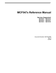
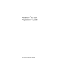
transferred to and from the mpc180 in order to process the context switch. Figure 16 shows an output from Windview (Tornado’s run-time analysis software). The
run-time scenario is depicted clearly, and shows the introduction of specific “Event
points”. These event points are instrumental in accurately measuring the execution
time of the AFHA unit. Note that the task labeled “t10” represents the execution of
the RC4 algorithm by the MPC180.
Using the event logging control library, wvEvent() is used to capture the exact
timing of the encryption and decryption sequences. The figure shows how the userdefined events show up during run-time analysis. The encryption cycle is composed
of two parts, namely, setting the key, and actually processing the data (encryption
or decryption). That is why the times are represented as a sum of two parts. The
timing obtained from the MPC180 running the RC4 algorithm is shown in table 1.
42
FIGURE 16: WindView timing graph for RC4.
Encrypting multiple sets of data with the AFHA:
It may be noted that the sequence of commands used to encrypt the data is:
1. mpc180AfhaSetKey()
2. mpc180AfhaProcess()
Thus, if it is desired to use the same key to continuously encrypt successive blocks
of data using the same key, mpc180AfhaSetKey() need be used only once, and
mpc180AfhaProcess() can be called as many times as is required.
The AFHA also supports context switching where current encryption is halted
and another stream is encrypted with a different key. The original encryption is then
resumed. The context switching depends on the “context” keyword in the arguments.
This allows for switching between two different encryptions using different values for
this variable.
43
4.2. Public Key Hardware Accelerator (PKHA) Module
The mpc180Pkha module performs advanced mathematical functions to support
RSA and ECC public key cryptographic algorithms. The PKHA module comprises
of three sub-modules. The names of the sub-modules are,
1. mpc180PkhaUtil
2. mpc180PkhaEcc
3. mpc180PkhaRsa
The first of the sub-modules, the mpc180PkhaUtil executes the following functions:
1. Load and read large number registers
2. Load and read the modulus size
3. Clear the register memory, and perform supporting calculations
The second sub-module, the mpc180PkhaEcc is used to perform elliptic curve cryptography. Elliptic Curve cryptography is supported in both F (2ˆn) and F(p). The
ECC module allows for two levels of operations. The first is high level, and executes
elliptic curve point multiplication using either projective or affine co-ordinates. The
second level allows for the execution of elliptic curve additions and point doubles.
These applications that run these operations are required to work with projective coordinates with all the inputs and outputs being in the Montgomery residue system.
The third sub-module, the mpc180PkhaRsa is used to perform modular arithmetic,
like the RSA algorithm, DSA algorithm and Diffie-Hellman. Again, the computations
are classified into two levels. The first level (high-level) performs modular exponentiation (XˆY mod N ). The second level of computation involves modular addition,
subtraction and multiplication. It may be noted that the minimum number of digits
that the RSA and ECC routines can work with are 128 and 32 respectively.
44
# of Repetitions
Time/Repetition (milliseconds)
% Error
1
160.5
1%
RSA
1
159.5
1%
Exponentiation
1
161.5
1%
1024 bit
1
156.5
1%
1
159.5
1%
TABLE 2: WindView timing for RSA exponentiation.
4.2.1. RSA Module
The basic functions of modular arithmetic are covered in this section. Modular
exponentiation, addition, subtraction and Montgomery multiplication are performed
for 1024 bit numbers.
RSA modular exponentiation:
• RSA Exponentiation ((XˆY mod N ))
• Routine used: mpc180RsaExpA()
• From the results in table 2, the average time = 159.5 milliseconds
It may be noted that RSA exponentiation is a slow process when compared to other
modular operations. RSA exponentiations involve repeated squaring and multiplication, and in our case we are using a 1024 bit exponent. This exponentiation would
alone require 1024 squaring operations and approximately 512 multiplications. Thus
the large timing required to perform RSA exponentiation.
RSA modular addition:
• 1024 bit RSA modular addition (B=A+B mod N)
45
# of Repetitions
Time/Repetition (microseconds)
% Error
RSA
625
4.8
1%
Modular
625
5.1
1%
addition
625
5.1
1%
1024 bit
625
4.8
1%
625
4.8
1%
TABLE 3: WindView timing for RSA modular addition.
• Routine used: mpc180RsaModularAdd()
• From the results in table 3, the average time = 4.92 microseconds
46
# of Repetitions
Time/Repetition (microseconds)
% Error
RSA
625
4.8
1%
Modular
625
5.1
1%
subtraction
500
4.9
1%
1024 bit
625
5.1
1%
625
5.1
1%
TABLE 4: WindView timing for RSA modular subtraction.
RSA modular subtraction:
• 1024 bit RSA subtraction
• Routine used: mpc180RsaModularSubtract()
• From table 4, the average time taken to execute was 5 microseconds
RSA modular multiplication:
• 1024 bit Montgomery multiplication:
• Routine used: mpc180RsaModularMultiply()
• From table 5, the average time taken to execute was 103.7 +/- 33 (1%) microsecs
Cross referencing the timing obtained above with the formula for running time of
the MPC180 during multiplication:
tmult1 = (1/F ) ∗ [(M S)2 + 10 ∗ (M S) + 27]
For our purposes,
F = Frequency of operation = 50MHz
MS = No. of 16-bit blocks in the modulus = 64
47
# of Repetitions
Time/Repetition (microseconds)
% Error
RSA
400
104.5
1%
Modular
500
101.5
1%
multiplication
500
104.5
1%
1024 bit
500
104.5
1%
500
103.5
1%
TABLE 5: WindView timing for RSA modular multiplication.
We then have:
tmult1 = (1/F ) ∗ [(M S)2 + 10 ∗ (M S) + 27]
= (1/(50 ∗ 106 )) ∗ [(64)2 + 10 ∗ (64) + 27]
= 96 microseconds
The windview timing from table 5 shows a timing of 103.7 microseconds, which is
reasonably close to the expected theoretical value.
Please refer to table 14 for an explanation of the variables used in the formulae for
the performance of the MPC180.
4.2.2. ECC Module
The Elliptic Curve Cryptography module performs elliptic curve point multiplication, elliptic curve point addition, elliptic curve point doubling, ECC modular addition. ECC modular subtraction, ECC modular multiplication and the Montgomery
modular multiplication in F(p). The above capabilities are tested and the results are
shown below.
48
ECC point addition in F(p):
• Elliptic curve point addition (R = P X Q; where P = {X1, Y1, Z1}, Q = {X2,
Y2, Z2} and Z = {X3, Y3,Z3}) in F(p).
• Routine used: mpc180EccAddPtoQ()
• From table 6, the average time taken to execute = 2189.6 +/- 26 (1%) microsecs
The above function has been tested by the function “timex”, from the WindView
timing library in order to get an average time.
Data :
X1 = {0x6472bc69, 0xd14ce7eb, 0x574d0000};
Y1 = {0xdd10558d, 0x61ad63b7, 0xd00f0000};
Z1 = {0x00000000, 0x00000000, 0x00010000};
X2 = {0x707c9fdf, 0xdfd914f1, 0xe2af0000};
Y2 = {0xa064d790, 0xf575c335, 0x722b0000};
Z2 = {0x00000000, 0x00000000, 0x00010000};
A = {0x00000000, 0x00000000, 0x00000000};
B = {0xe24bda1c, 0x878e451c, 0x3b2a0000};
modulus ={0xe29bdac8, 0x7c83251c, 0xb24d0000};
ECC point addition in F (2ˆn):
• Running the above test in F (2ˆm)
• From table 7, the average time to execute = 1869.8 +/- 26 (1%) microsecs
ECC point doubling:
• Elliptic curve point doubling
49
# of Repetitions
Time/Repetition (microseconds)
% Error
ECC
625
1891
1%
addition
625
2158
1%
F(p)
500
2264
1%
625
2424
1%
625
2211
1%
TABLE 6: WindView timing for ECC addition in F(p).
# of Repetitions
Time/Repetition (microseconds)
% Error
ECC
500
1998
1%
addition
625
1891
1%
F(2n)
500
1731
1%
625
1811
1%
625
1918
1%
TABLE 7: WindView timing for ECC addition in F(2n).
• Routine used: mpc180EccDoubleQ()
Data Used:
B = {0xec8a7a0b, 0x05a00a4c, 0x6b880000};
X1 = {0x20f9d2a6, 0x9fb3d9cb, 0x7ee70000};
Y1 = {0x35c900a5, 0x678c976d, 0x789f0000};
Z1 = {0x00000000, 0x00000000, 0x00010000};
A = {0x00000000, 0x00000000, 0x00000000};
MODULUS = {0xec8a7a0b, 0x05a00a4c, 0x6b8b0000};
50
# of Repetitions
Time/Repetition (microseconds)
% Error
ECC
625
1518
1%
point doubling
625
1651
1%
F(p)
500
1898
1%
625
1971
1%
625
1838
1%
TABLE 8: WindView timing for ECC point doubling in F(p).
Similar to the tests above, elliptic point doubling was carried out and the timing
was obtained using the “timex” routine:
ECC point doubling in F(p):
• Point doubling in F(p)
• From table 8, the average time to execute = 1381 +/- 26 (1%) microsecs
ECC point doubling in F (2ˆn):
• Point Doubling in F (2ˆm):
• From table 9, the average time to execute = 1382.2 +/- 26 (1%) microsecs
For elliptic curve point multiplication, the routine used is mpc180EccMultPtoQ().
4.3. Random Number Generator (RNG) Module
The mpc180Rng module performs random number generation, and provides applications with 32-bit numbers. The mpc180Rng has two interfaces, wherein one
interface generates a single 32-bit random number (mpc180Rand), the other generates a block of random numbers of a specified length (mpc180RandLongs). The
timing includes testing for randomness.
51
# of Repetitions
Time/Repetition (microseconds)
% Error
ECC
625
2211
1%
point doubling
625
1624
1%
F(2n)
625
1678
1%
625
1784
1%
625
1864
1%
TABLE 9: WindView timing for ECC point doubling in F (2ˆn).
# of Repetitions
Time/Repetition (microseconds)
% Error
175
5236
1%
32-bit
175
5331
1%
RNG
175
5236
1%
175
4283
1%
175
5045
1%
TABLE 10: WindView timing for 32-bit RNG generation.
32-bit random number generation:
• Routine used to generate one 32-bit rng is mpc180rand
• From table 10, the time required to generate one 32-bit random number is
approximately 50.26 microseconds
100 block 32-bit random number generation:
• Routine used to generate 100 32-bit rng blocks is mpc180RandLongs
• From table 11, the time required to generate one 32-bit random number is
approximately 5606 microseconds
52
# of Repetitions
Time/Repetition (microseconds)
% Error
100
175
5235
1%
32-bit
175
5246
1%
RNG’s
175
5617
1%
175
5469
1%
175
6283
1%
TABLE 11: WindView timing for 100 blocks of 32-bit RNG generation.
Sample 32-bit random numbers generated are shown below:
0x31f4c0: value = -117361797 = 0xf901337b
0x31f4c0: value = -1402180736 = 0xac6c6b80
0x31f4c0: value = 850937036 = 0x32b844cc
0x31f4c0: value = 1952494407 = 0x7460b347
WindShell displays the output in the above format, giving us a random number
value in both decimal form(−117361797), as well as hexadecimal form (0xf901337b).
4.4. Message Digest Hardware Accelerator (MDHA) Module
The mpc180Mdha message digest hardware accelerator module is capable of performing hash algorithms like the SHA-1 and MD5. It is also capable of generating an
HMAC, which can be built upon an existing message digest calculation.
The basic routine used in these calculations is “mpc180Hash()”. The arguments
of this function are algorithm, input buffer, length of message, output buffer. The
algorithm parameter specifies which algorithm this function must use to generate the
hash, and possible values are SHA-1 and MD5. The output buffer must be able to
hold 16 bytes for MD5 and 20 bytes for SHA-1.
53
# of Repetitions
Time/Repetition (microseconds)
% Error
400
3331
1%
400
2998
1%
400
3748
1%
400
2831
1%
400
2581
1%
SHA-1
TABLE 12: WindView timing for SHA-1.
SHA-1 hashing:
• Routine used to perform SHA-1 hashing is mpc180Hash(MDHA SHA1)
• Average time to execute SHA-1 for a data length of 241 bytes is 3097.8 +/- 41
(1%) microsecs
MD5 hashing:
• Routine used to perform MD5 hashing is mpc180Hash(MDHA MD5)
• Average time to execute MD5 for a data length of 131 bytes is 2781 +/- 41 (1%)
microsecs
54
MD5
# of Repetitions
Time/Repetition (microseconds)
% Error
500
2531
1%
400
3414
1%
400
2706
1%
400
2456
1%
400
2789
1%
TABLE 13: WindView timing for MD5.
The timing formulae for the PKHA embedded routines provided in the user’s manual are shown in table 14 [3]. The following definitions apply to the symbols in the
table:
F = operating frequency
MS = number of 16-bit blocks in the modulus
Ne = number of bits in the exponent or multiplier (k)
avg = average run time (assumes half of the bits in the exponent are 1’s)
wcs = worst case run time
bcs = best case run time
55
Operation
Symbol
Run-Time Formula
multPtoQ
tmulf p (avg)
N e ∗ tdblf p + 0.5 ∗ N e ∗ taddf p + 8 ∗ (tmult1 ) + 6 ∗ (M S)move
FpAddPtoQ
taddf p
16 ∗ (tmult1 ) + 4 ∗ (tadd ) + 5 ∗ (tsub ) + 19 ∗ (M S)move
FpDoubleQ
tdblf p
10 ∗ (tmult1 ) + 11 ∗ (tadd ) + 2 ∗ (tsub ) + 10 ∗ (M S)move
multPtoQ
tmulf 2m (avg)
N e ∗ tdblf 2m + 0.5 ∗ N e ∗ taddf 2m + 8 ∗ (tmult1 ) + 6 ∗ (M S)move
F2maddPtoQ
taddf 2m
20 ∗ (tmult1 ) + 7 ∗ (tadd ) + 15 ∗ (M S)move
F2mdoubleQ
tdblf 2m
10 ∗ (tmult1 ) + 4 ∗ (tadd ) + 9 ∗ (M S)move
expA
texp (avg)
1.5 ∗ N e ∗ [tmult1 ] + tmult1 (wcs)
modularmultiply
tmult1 (wcs)/tmult1 (bcs)
(1/F ) ∗ [(M S)2 + 10 ∗ (M S) + 27]/(1/F ) ∗ [(M S)2 + 9 ∗ (M S) + 22]
modularmultiply2
tmult2 (wcs)/tmult2 (bcs)
2 ∗ tmult1 (wcs)/2 ∗ tmult1 (bcs)
modularadd
tadd (wcs)/tadd (bcs)
(1/F ) ∗ [4 ∗ (M S) + 11]/(1/F ) ∗ [3 ∗ (M S) + 6]
modularsub
tsub (wcs)/tsub (bcs)
(1/F ) ∗ [3 ∗ (M S) + 11]/(1/F ) ∗ [2 ∗ (M S) + 6]
r2
tr2
tbd
clearmemory
tclr
ram
(1/F ) ∗ 4 ∗ (M S + 5)
TABLE 14: Run Time Formulae.
56
5.
Discussion
5.1. Analysis
This chapter discusses the results gathered during the course of this thesis. The
MPC180 was tested for timing and performance by running code for today’s currently
used cryptographic algorithms. The following sections will present the conclusions and
discuss future directions of research in embedded cryptography.
As mentioned before, Tornado was used to write code and time various routines
supported by the MPC180. The BSP (Board Support Package) supplied with the
MPC180 was written for use with Tornado version 2.02 in mind. At the lab however,
the computers were equipped with Tornado 2.2. This initially presented us with many
problems and compatibility issues, such as malfunctioning target servers and project
creation errors. So, I had to go back to using version 2.02, which took care of many
of the problems. After a few modifications to the configuration, I managed to get
the board to boot. To ensure proper migration when and where possible, WindRiver
Systems provides a “Migration Guide” that is a useful reference to have.
The results obtained in the previous chapter are indicative of the performance of
the MPC180 security processor, when tested on a Pentium processor, running at 1.7
Ghz. Upon comparison with current software benchmarks [13], the performance of
the MPC180 appears to be slower. But it must be taken into account that today’s
standard benchmarks for cryptographic libraries in C++, called Crypto++ 5.1 [13],
were tested after various optimizations for speed and Pentium 4 code generation, and
were tested on a Pentium 4 2.1 GHz machine running Windows XP.
6
The timing
of the Crypto++5.1 [13] libraries for 1024 bit RSA encryption is 0.18 milliseconds,
while the MPC180 takes around 160 milliseconds for a 1024 bit RSA exponentiation. There are other hardware solutions for cryptography being developed. As an
6
These libraries were compiled with Microsoft VC++.NET.
57
example, SCI Worx’s high performance RSA co-processor performs a 1024-bit RSA
exponentiation in 33 milliseconds [14]. SIDSA’s RSA co-processor performs 1024-bit
RSA exponentiation in 60 milliseconds [15]. The underlying point to be noted here,
is that the MPC180 does not claim to be faster than software implementations. It is
a dedicated solution to encrypting network traffic, and its purpose is to shoulder the
complete responsibility of performing cryptography while the host processor performs
its other duties while not being bogged down by the load of intensive cryptographic
computations. A hardware implementation also provides a critical advantage from
the security viewpoint. The hardware implementation is tamper proof and ensures
that sensitive information like secret keys are not compromised. Software implementations, on the other hand, are susceptible to reverse engineering and other common
attacks.
5.2. Conclusions
This work presented the benchmarking of Motorola’s MPC180 security co-processor.
This processor is intended for use with Motorola’s POWERQUICC family of communication processors, and it was tested by running code for various cryptographic
algorithms and operations like RSA [5, 16], stream ciphers (RC4), message digests,
random number generation and operations over Elliptic curves [17]. This security
co-processor has shown that it performs intensive computations with good timing,
while offloading this burden from the host processor. The MPC180 is thus a good
solution to provide dedicated network security.
58
5.3. Future work
Future directions of work with the MPC180 security co-processor could aim towards application development, turning it into a “cryptographic box” so to speak.
7
This system would function as a very secure server peripheral providing dedicated
cryptographic support for all network traffic.
7
Similar to nCipher’s nShield products [18].
59
BIBLIOGRAPHY
1. Michael Barr, Programming Embedded Systems in C and C++, O’Reilly, first
edition, January 1999.
2. Jorge Guajardo Thomas Wollinger and Christof Paar, “Cryptography in embedded systems: An overview,” 2003.
3. Motorola Semiconductors Inc., “MPC180LMB Security processor user’s manual
rev 1.3,” 2002.
4. Micetek International Inc., “mpc860 processor card user’s manual,” October
2000.
5. L. Adleman, R. L. Rivest, and A. Shamir, “A method for obtaining digital
signature and public-key cryptosystems,” Comm. of the ACM, vol. 21, no. 2,
pp. 120–126, February 1978.
6. S.R. Ball, Embedded Microprocessor Systems: Real World Design, Newnes, third
edition, November 2002.
7. WindRiver Systems, ”VxWorks 5.4 Programmers Guide”, First edition, March
1999.
8. WindRiver Systems, ”Tornado 2.2 Users Guide, Windows Edition”, August
2002.
9. John Gordon, “The vxworks cook book,” 2003.
10. J.A. Borkhuis, “VxWorks / Tornado II FAQ,” 2003.
11. WindRiver Systems, “Tornado 2.0 Getting Started Guide,” .
12. Brian W. Kernighan and Dennis Ritchie, The C Programming Language, Prentice Hall PTR, second edition, March 1988.
13. “Crypto++ 5.1 benchmarks,” http://www.eskimo.com/eweidai/benchmarks.
14. “High performance rsa co-processor, www.sci-worx.com,” .
15. “Sidsa rsa2048a rsa co-processor, www.sidsa.com,” .
16. Ç. K. Koç, High Speed RSA Implementation, RSA Laboratories, second edition,
November 1994.
17. N. Koblitz, “Elliptic curve cryptosystems,” Mathematics of computation, vol.
48, no. 177, pp. 203–209, January 1987.
60
18. “nShield: A hardware security module from nCipher,”
http://www.ncipher.com/nshield/index.html.