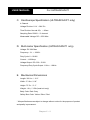
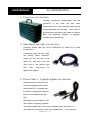
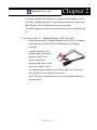
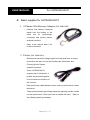
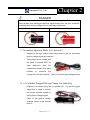
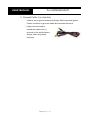
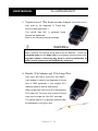
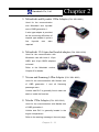
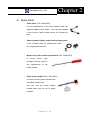
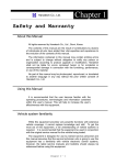
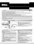
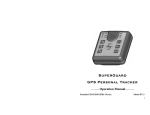
1
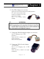
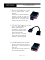
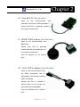
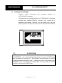
Hanatech Co., Ltd. Chapter 2 Specification and Parts I. Specification ----------------------------------A. Hardware CPU: 16bit, 33MHz RAM: 1 Mbyte (SRAM) Program Cartridge Memory: 512Mbytes Flash Memory Display: 320×240 Monochrome Graphic LCD with Back Light Key Pad: 24 membrane keys, embossing type Port: RS232 , USB Printer: General PC printer Power: DC 12V, 1,200mA B. Environmental Specification Indoor use only Operating temperature: Max 50℃ / 122℉ Maximum relative humidity: 80% (up to 31℃/88℉) and 50% (40℃/104℉ or higher) Installation overvoltage categories: CATⅡ Maximum measurable voltage: DC 30V Max Pollution degree 2 Max. Altitude: Up to 2000m Chapter 2 - 1 USER MANUAL For ULTRASCAN P1 C. Oscilloscope Specification (ULTRASCAN P1 only) 4 Channel Voltage Division: 0.1V ~ 20V Div Time Division: Normal 25㎲ ~ 20sec Sampling Rate: 500K㎐ / 2 channel Measurable Voltage: DC 150V Max D. Multi-meter Specification (ULTRASCAN P1 only) Voltage: DC 30V Max Frequency: 1㎐ ~ 100K㎐ Duty Cycle: 0 ~ 99.9% Current: ±128 Amp Voltage Output: DC 0.00 ~ 5.00V Frequency/Duty Cycle Output: 1.0Hz ~ 1.0KHz E. Mechanical Dimensions Length: 302.1㎜ / 12.1" Width: 171.9㎜ / 6.8" Height: 75.7㎜ / 3.1" Weight: 1.6㎏ / 3.5lb (head unit only) Body Color: Dark Grey Safety Boot Color: Yellow / Blue / Red * All specifications are subject to change without notice for the purpose of product and quality improvement. Chapter 2 - 2 Chapter 2 Hanatech Co., Ltd. II. Part List ----------------------------------------A. Head unit and basic supplies 1. Head Unit (P/N. 1000-0005) - Made of strong ABS resin, each unit has passed internal impact test before shipment. - As the inner surface is coated with antielectromagnetic interference material, it neither interfere the other electronic devices nor get interfered by the other equipments. 2. Safety Boot (P/N. 2002-0030) - Flexible plastic cover that protects the head unit from physical, chemical and electrical damage - Yellow boots are used for ULTRASCAN P1, and blue and red boots are also available upon distributor’s demand. Chapter 2 - 3 USER MANUAL For ULTRASCAN P1 3. Carry Case (P/N. 3003-0003) Provides convenient transportation and the protection of the head unit and other components from outer physical impact during the transportation and storage. Carry case is provided when purchasing the head unit and at least one diagnostic adaptor kit together. Includes keys and dial lock 4. Main Data Link Cable (P/N. 3001-0001) - Connects vehicle side DLC and ULTRASCAN P1 head unit for data transmission. - Connecting parts on both ends are exactly same, therefore, simply put any one end to the head unit, and then hook the other end to the vehicle side DLC after connecting an appropriate adaptor 5. Power Cable 1 – Cigarette Lighter (P/N. 3000-0004) - Supplies power to the head unit from the cigarette lighter socket. Used when DLC is located near the driver or passenger seat and power is not supplied through DLC. - LED lights on both ends turn ON when power is properly supplied. - The metal plunger part in the end of cigarette lighter connector is removable by unscrewing for the fuse replacement. Chapter 2 - 4 It may become Hanatech Co., Ltd. Chapter 2 loose over repeated use, therefore, it is highly recommended to check if it is tightly screwed frequently. A set of plunger parts are included in the basic supplies. Refer to spare parts section hereinafter. - The rated voltage and current for this power cable are 12V and less than 2A. 6. Power cable 2 – Vehicle Battery (P/N. 3000-0005) - Supplies power from the vehicle battery when the DLC is located in the engine bay or when using the oscilloscope or multi-meter functions - Connect each of the two alligator clips to the battery terminal of the correct polarity with caution. - Must be used together with the Power Cable 1. Insert the cigarette lighter adaptor of the Power Cable 1 into the socket, and connect the other end to the head unit. - Red LED light turns ON when power is properly supplied from the vehicle battery. Chapter 2 - 5 USER MANUAL For ULTRASCAN P1 B. Basic supplies for ULTRASCAN P1 1. 4 Channel Oscilloscope Adapter (P/N. 3000-0007) - Collects and delivers electrical signal from the probes to the head unit for oscilloscope, multimeter and ignition pattern analysis functions. - Refer to the manual book 2 for further information 2. Probes (P/N. 3000-0001) - Obtains and transmits voltage signal from electrical wire or sensor terminal to the main unit for the Oscilloscope, Multimeter and Primary Ignition Pattern Analysis functions. - Since ULTRASCAN P1 supports up to 4 channels, 4 probes are provided together for the maximum utilization of the function. - Each probe has rubber bands of same color on both ends for easier distinction. - These probes directly get voltage signal by applying a probe needle into the electric wire, which you have to handle with care. the following warning message. Chapter 2 - 6 Refer to Chapter 2 Hanatech Co., Ltd. DANGER Note that the probe has a needle while the Secondary Ignition Probe does not. These probes with needle get electrical signal directly from the wire, therefore, extending them to high voltage lines is extremely dangerous. Probe with needle Probe without needle 3. Secondary Ignition Probe (P/N. 3000-0002) - Applied to the high tension spark plug wires to get the secondary ignition voltage signal by induction. - The probe has no needle and the body is colored RED for clear distinction from the oscilloscope probes that have needles to measure the voltage from the wire directly. Refer to the warning message above. 4. #1 Cylinder Trigger Pick-up Clamp (P/N. 3000-0003) - Clipped on the spark plug wire to cylinder No. 1 to get the trigger signal that is used to identify the correct cylinder number of each ignition voltage signal. - Refer to the ignition pattern analysis section in the manual book 2. Chapter 2 - 7 USER MANUAL For ULTRASCAN P1 5. Ground Cable (P/N. 3000-0006) - Used for circuit ground while using Scope, Multi-meter and Ignition Pattern functions to get more stable and accurate test result. - Highly recommended to extend this cable to the (-) terminal of the vehicle battery always when using these functions. Chapter 2 - 8 Chapter 2 Hanatech Co., Ltd. C. Diagnostic Adapters Diagnostic adapters may be sold separately, therefore check if all the adapters you ordered are included in the package upon delivery. There are two types of adapters: capsulated and wired types. Most of ULTRASCAN P1 adapters are capsulated for better durability and storage, however, sometimes it is difficult or almost impossible to connect the capsulated adapter to vehicle side DLC when it is located deep inside beneath the dashboard. We use wire type adapters for the cars such as Hyundai and Kia that we were reported to have such connecting difficulties. Capsule type Wire type 1. OBD2 Standard Adapter (P/N. 3001-0010) Used for all OBD generation 2 and EOBD compatible vehicles. Vehicle side DLC is generally located near the driver’s seat and most frequently found beneath the dash panel. 2. Toyota / Lexus 17Pin Rectangular Adapter (P/N. 30010011) Used for the diagnosis of Toyota and Lexus of OBD generation 1. Vehicle side DLC of this type is generally located in the engine compartment. Chapter 2 - 9 USER MANUAL For ULTRASCAN P1 3. Toyota/Lexus 17Pin Semi-circular Adapter (P/N. 3001-0012) Also used for the diagnosis of Toyota and Lexus of OBD generation 1. The vehicle side DLC is generally found beneath the dashboard. Refer to the following warning message. WARNING The appearances of this adapter and MAZDA 17Pin adapter are exactly same, however, the internal wiring and circuit are different. Check the engraved name and the body color of the adapter carefully before use. Improper adapter connection may result in serious malfunction of either control system and ULTRASCAN P1 head unit. 4. Honda 3 Pin Adapter and 2 Pin Jump Wire (P/N. 3-pin: 3001-0014, 2-pin wire: 3001-0023) 3-pin adapter is used for the diagnosis of Honda cars of OBD generation 1 that support DTC read and erase as well as data stream. Older Honda cars have 2-pin DLC that supports DTC read only. The jump wire is used for these older cars to bridge the 2-pin DLC terminals. The vehicle side DLC is generally located under the dashboard or the glove box. Chapter 2 - 10 Hanatech Co., Ltd. Chapter 2 5. Mitsubishi and Hyundai 12Pin Adapter (P/N. 3001-0001) Used for the communication with Mitsubishi and Hyundai cars of OBD generation 1. A wire type adapter is provided as the connecting difficulties of capsule type adapter in quite a few Hyundai cars were reported. 6. Mitsubishi 12+16pin dual headed adapter (P/N: 3001-0030) Used for the communication with Mitsubishi cars with both of 12-pin OBD1 and 16-pin OBD2 adapters on-board. Refer to the Mitsubishi section, Chapter 6 for details. 7. Nissan and Samsung 14Pin Adapter (P/N. 3001-0006) Used for the communication with Nissan cars of OBD generation 1 and all Samsung passenger cars. Vehicle side DLC is generally found under the dash or inside the fuse box. 8. Mazda 17Pin Adapter (P/N. 3001-0013) Used for the communication with Mazda cars of OBD generation 1. Vehicle side DLC is generally located in the engine compartment. Refer to the warning message in the next page: Chapter 2 - 11 USER MANUAL For ULTRASCAN P1 WARNING The appearances of this adapter and Toyota 17Pin SEMI-CIRCULAR adapter are exactly same, however, the internal wiring and circuit are different. Check the engraved name and the body color of the adapter carefully before use. Improper adapter connection may result in serious malfunction of either control system and ULTRASCAN P1 head unit 9. Subaru 9Pin Adapter (P/N. 3001-0022) Used for the communication with Subaru cars of OBD generation 1. The vehicle side DLC is generally located beneath the dashboard. 10. GM Daewoo 12Pin Adapter (P/N. 3001-1002) Used for the communication with Daewoo cars of OBD generation 1. The vehicle side DLC is generally located beneath the glove box, door side. 11. Kia 6Pin Adapter (P/N. 3001-0003) Used for the communication with old Kia cars of OBD generation 1. Only the Diagnostic Trouble Code reading function is available for the cars with this type of adapter as only the slow pulse signal is transmitted through the vehicle side DLC. The split wire of the adapter is to be connected to the ground terminal of the vehicle side DLC. Chapter 2 - 12 Chapter 2 Hanatech Co., Ltd. 12. Kia 20Pin Adapter (P/N. 3001-0004) Used for the communication with Kia cars of OBD generation 1. DTC read & erase and data stream functions are available for the cars with this type of adapter. Refer to the following warning message. WARNING The appearances of Kia 20Pin adapter and Ssangyong 20Pin Rectangular adapter are exactly same, however, the internal wiring and circuit are different. Check the engraved name and the body color of the adapter carefully before use. Improper adapter connection may result in serious malfunction of either control system and ULTRASCAN P1 head unit 13. Ssangyong 20Pin Rectangular Adapter (P/N. 3001-0005) Used for Ssangyong cars of OBD generation 1. Vehicle side DLC is located in the engine compartment. Refer to the warning above. 14. Ssangyong 14Pin Circular Adapter (P/N. 3001-0007) Used for old Ssangyong cars of OBD generation 1. Vehicle side DLC is located in the engine compartment. Chapter 2 - 13 USER MANUAL For ULTRASCAN P1 15. Holden 6 Pin Adapter (P/N. 3001-0023) Used for Australian Holden of OBD generation 1. Japanese cars such as Toyota and Nissan assembled in Australia with Holden built engines may have this type of adapter, too. Vehicle side DLC is generally located beneath the glove box to the center facia. 16. GM Opel 10Pin Adapter (P/N. 3001-0019) Used for the communication with Opel cars of OBD generation 1. Also applied to Australian Holden, South American Opel and European Vauxhall software packages. Vehicle side DLC is generally located in the fuse box beneath the dashboard or near the parking brake. 17. Ford 20 Pin Adapter (P/N. 3001-0020) Used for the communication with Ford cars of OBD generation 1, including Australian and British Fords. Vehicle side DLC is generally located in the fuse box beneath the dashboard. Chapter 2 - 14 Chapter 2 Hanatech Co., Ltd. 18. Ford EEC-IV (P/N. 3001-0017) Used for the communication with Australian Ford cars of OBD generation 1, Vehicle side DLC is generally located in the engine compartment. 19. BMW 20Pin Adapter (P/N. 3001-0016) Used for the communication with BMW cars. Vehicle side DLC is generally located beneath the dashboard or in the engine compartment. (Can be supplied as an optional part) 20. VAG 2X2Pin Adapter (P/N. 3001-0029) Used for the communication with the OBD1 generation cars of Volkswagen / Audi Group including SEAT and Skoda, Vehicle side DLC is located in various place on the vehicle but generally around dashboard. (Can be supplied as an optional part) Chapter 2 - 15 USER MANUAL For ULTRASCAN P1 21. Mercedes Benz 38Pin Adapter (P/N. 3001-0015) Used for the communication with OBD1 generation Mercedes Benz cars Vehicle-side adapter is found in the engine compartment. Applied with the models e.g) C202, CLK208, E210, E124, S140, SL129, SLK170, G463, G461. (Can be supplied as an optional part) 22. Mercedes Benz 4Pin Adapter (P/N. 3001-0009) Used for the communication with early 1990’s or earlier model year Mercedes Benz cars e.g) C201, E124, S126, SL107, G463 (Red: Battery +, Gray: K Line,, Yellow : Ignition check, Black: Ground) (Can be supplied as an optional part) 23. Upgrade cable (P/N. 3000-0010) To be connected to main data link cable for updating your ULTRASCAN P1 software by downloading updated codes from your PC. Refer to the related chapter in this manual. Chapter 2 - 16 Chapter 2 Hanatech Co., Ltd. 24. Internal ULTRAPLEXER (P/N. 3001-0032) Chrysler 12+16Pin cable 15Pin D Sub (to Main Cable => Scanner) to 12+16Pin adaptor (to Sebring/Stratus vehicle side adaptor) 25. Fiat 3Pin (P/N. 3001-0031) Used for the communication with OBD1 generation cars of Fiat the Group. Vehicles side DLC is located in various place on the vehicle but generally around dashboard. (Can be supplied as an optional part) 26. DC POWER CABLE (P/N. 3001- Chapter 2 - 17 ) USER MANUAL For ULTRASCAN P1 D. Software Cartridge - Contains vehicle information and operating software for ULTRASCAN P1 scanners. - The appearance and measurements for ULTRASCAN P1 cartridges complies with standard PCMCIA, however, inner circuits are of Hanatech’s own design. Therefore, you can neither use it with the other equipment nor copy its contents to the other standard PCMCIA. WARNING MAKE SURE TO TURN POWER OFF BEFORE REMOVING OR INSERTING A CARTRIDGE. It is extremely dangerous to insert or remove a PCMCIA card while the head unit is turned on. Both PCMCIA card and head unit can be critically damaged and broken down. Always turn power off by pressing the [POWER] key or removing power supply cable from the head unit before inserting or removing a PCMCIA card.. Chapter 2 - 18 Chapter 2 Hanatech Co., Ltd. E. Spare Parts - Extra fuses (P/N. 3008-0003) For the replacement of the fuse located inside the cigarette lighter power cable. You can also replace it with a fuse of which rated current is 2 Ampere or less. - Spare cigarette lighter power cable plunger parts A set of spare parts for replacement when the original parts are lost. - Wrench for probe needle replacement (P/N. 3008-0002) A screw driver type hexagon wrench used for the replacement of the probe needle. - Extra probe needles (P/N. 3008-0001) A couple of short spare needles and extended needle units. You can use any metal sawing needle when you run out of spare needles. Chapter 2 - 19 USER MANUAL For ULTRASCAN P1 F. Optional Supplies 1. Host-Pro PC Interface software CD. - Consisted of a software installation CD (P/N. 3005-0002), 5 meter USB cable (P/N. 3000-0014). - Enables realtime PC interface of ULTRASCAN P1 scanners. Refer to the PC interface section of this manual and the separate HOSTPRO user manual for further information. * The latest version of Host Pro PC Interface software CD will be included with the each kit but CD may not be included with the kit without any notice. . Chapter 2 - 20