1
1. AN OVERVIEW OF THE LD220 MODBUS SYSTEM
The LD220 is a series of dual channel inductive loop detectors. The use of microprocessor
and surface mount technology enables a large number of functions to be incorporated into a
small package. The LD220 is compatible with most dual channel detectors on the market and
is easy to set-up and install. All configuration is done through the communications port.
The LD220 is supplied with a RS485 communications port. The LD220R is supplied with a
RS232 communications port.
Typical applications in the parking and access control environments are safety loops, arming
loops and entry or exit loops and direction logic with counting.
The LD220 consists of an inductive loop detector with an integral RS485 communications
port. The unit has been developed to enable remote monitoring and control of the loop
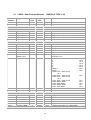
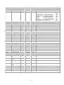
detector over a RS485 network. The communications allows access to internal setup
parameters such as sensitivity, timers, as well as counters. The LD220 can be multi-dropped
on the RS485 network with other detectors and logic units, or linked to a PC running software
for configuration and monitoring of the parking system. Non volatile memory is used to store
counters and all configuration parameters.
Standard features of the logic on the unit are :
· RS485 Communications Port.
The RS485 communications port enables up to 127 detectors to be networked on a single
twisted pair cable. The LD220 communicates using the Modbus protocol in Binary mode. All
configuration data is held in modbus registers and can be setup by a PC or PLC on the
network.
· Selectable Pulse Time.
This feature sets the length of time that the pulse relay will be energized.
· Pulse Relay Selection.
The Pulse relay may be configured to energize on detection of a vehicle or when the vehicle
leaves the loop.
· Sensitivity Boost.
This feature sets the undetect level to maximum sensitivity and is used to prevent loss of
detection of high-bed vehicles.
· Switch selectable Sensitivity.
The detect sensitivity is the minimum change in inductance required to produce a detect
output. (%ΔL/L) .
· Switch selectable Frequency.
The frequency of the loop is determined by the inductance of the loop and the frequency
switch setting. If the frequency switch is on, the frequency is reduced. It may be necessary to
change the frequency to prevent cross-talk between adjacent loops.
· Filter Option.
3