1
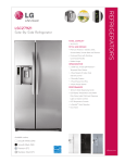
REFRIGERATOR
SERVICE MANUAL
CAUTION
PLEASE READ THE SAFETY PRECAUTIONS OF THIS MANUAL CAREFULLY
BEFORE REPAIRING OR OPERATING THE REFRIGERATOR
MODELS:
LSC27921SW
LSC27921ST
LSC27921TT
LSC27921SB
WARNINGS AND SAFETY PRECAUTIONS .......................................................................... 3
1. SPECIFICATIONS ............................................................................................................... 4
2. PARTS IDENTIFICATION .................................................................................................... 5
3. HOW TO INSTALL THE REFRIGERATOR ......................................................................... 6
4.HOW TO DISASSEMBLY AND ASSEMBLE ....................................................................... 10
5. MICOM FUNCTION ............................................................................................................. 15
6. EXPLANATION FOR MICOM CIRCUIT .............................................................................. 24
7. ICEMAKER AND DISPENSER WORKING PRICIPLES AND REPAIR .............................. 40
8. CIRCUIT ...............................................................................................................................46
9. TROUBLE DIAGNOSIS .......................................................................................................47
10. EXPLODED VIEW ............................................................................................................. 85
-2-
WARNINGS AND PRECAUTIONS FOR SAFETY
Please observe the following safety precautions to use the
refrigerator safely and correctly and to prevent accident or
injury when servicing.
1. Be careful of an electric shock. Disconnect power cord from
wall outlet and wait for more than three minutes before
replacing PCB parts. Shut off the power whenever replacing
and rapairing electric components.
2. When connecting power cord, wait for more than five
minutes after power cord was disconnected from the wall
outlet.
3. Check if the power plug or card is pinched between the
refrigerator and the wall. If the cord is damaged, it could cause
fire or electric shock.
8. Do not fray, damage, run over, kink, bend, pull out, or twist
the power cord.
9. Please check for evidence of moisture intrusion in the
electrical components. Replace the parts or mask with
insulation tape if moisture intrusion was confirmed.
10. Do not touch the icemaker with hands or tools to confirm
the operation of geared motor.
11. Do not suggest that customers repair their refrigerator
themselves. This work requires special tools and knowledge.
Non-professionals could cause fire, injury, or damage to the
product.
4. If the wall outlet is ocerloaded, it may cause a fire. Use a
dedicated circuit for the refrigerator.
12. Do not store flammable materials such as ether,
benzene, alcohol, chemicals, gas, or medicine in the
refrigerator.
5. Be sure the outlet is grounded. This is particulary important
in wet or damp areas.
13. Do not put anything on top of the refrigerator, especially
something containing water, like a vase.
6. Use standard electrical components.
14. Do not put glass bottles full of water into the freezer. The
contents will freeze and break the glass period.
7. Make sure hooks are correctly engaged.
Remove dust and foreign materials from the housing and
connecting parts.
15. When you scrap or discard the refrigerator, remove the
doors and dispose of it where children are not likely to play in
or around it.
-3-
Color
Black
Titanium
Case Material
Embo (normal)
PCM Stainless VCM
35 x 35 x 70 in.
Door Material
Net Weight
266.6 lbs.
Handle Type
LSC27921SB
LSC27921TT
LSC27921ST
LSC27921SW
SPECIFICATIONS
Dimensions
VCM
Vista
27 cuft
Display Graphic
Refrigerant
R134a
Basket, Quantity
4 Full
Ice Tray & Bank
Auto Ice maker+Space Plus
Climate class
Temperate (N)
Rated Rating
115V / 60Hz
Cooling System
Fan Cooling
MICOM control
Buckey, Dairy
Yes
Tray, Drawer
Yes
Dispenser Lamp
LED (2EA)
Yes (4) 40W/Blue
Heater Defrost
Shelf
1(FIX)+2(S/OUT)
Cyclo, Pentane
Tray meat
Yes
EGX90HLC Starting Type: TSD-115V
Egg Bank
No
Evaporator
Fin Tube Type
Condenser
Wire Condenser
FREEZER
Lamp
Insulation
Lubricanting Oil
ICE PLUS
Full Automatic
Defrosting System
Compressor
REFRIGERATOR
Capacity
Temperature Control
GENERAL FEATURES
MODELS
Stainless
LSC27921SB
Super White
LSC27921TT
LSC27921ST
SPECIFICATIONS
LSC27921SW
MODELS
1. SPECIFICATIONS
Ester ISO/10 280ml (9.47 fl.oz)
Drier
Basket, Quantity
Plastic (3)
Lamp
Yes (1) 40W/Blue
Shelf
3EA(WIRE)
MOLECULAR SIEVE XH-7
Capillary Tube
ID Ø0.85
First Defrost
4 - 6 Hours
Defrost Cycle
13 - 70 Hours
Desfrosting Device
Heater, Sheath
Anti-freezing Heater
Water Tank Heater
724 mm (281/2
779 mm (305/8 in.)
830 mm (325/8 in.)
891 mm (355/16 in.)
1261 mm (495/8 in.)
in.)
16
1771 mm
(6911 /
1746.5 mm (683/4 in.)
1741.5 mm (681/2 in.)
1771 mm (6911 /16 in.)
912 mm (35 29/32 in.)
908 mm (35 11/16 in.)
Front View
Top View
-4-
2. PARTS IDENTIFICATION
G
A
H
B
I
J
C
K
D
H
L
A
M
E
A
L
F
Use this page to become more familiar with the parts and features. Page references are included for your
convenience.
Note: This guide covers several different models.The refrigerator you have purchased may have some or
all of the items listed below. The locations of the features shown below may not match your model.
A
Freezer Door Rack
J
Refrigerator Shelf
B
Ice Bin
K
Snack Pan
For storage of ice cubes made by the icemaker.
Do not store anything except ice in the ice bin.
C
Freezer Lamp
D
Freezer Shelf
E
Drawer
F
Base Grille
G
Dairy Corner
For storage of meat or fresh food.
L
Refrigerator Door Rack
M
Vegetable Drawer
PCB Cover
Display Frame
For storage of dairy products
such as butter and cheese.
H
Refrigerator Lamp
I
Water Filter
Ice & Water
Dispenser Button
-5-
Water Tubes
3. HOW TO INSTALL THE REFRIGERATOR
1. DOOR ALIGNMENT
Adjust the level when the refrigerator door is lower than
the freezer door during the installation of the refrigerator.
Before adjust the doors, remove the Base Grille.
Tools you need
• Wrench 5/16 in (8 mm)
• Wrench 3/4 in (19 mm)
If the freezer compartment door is lower than
the refrigerator compartment door, make them
level by inserting flat blade screwdriver into the
groove of the left leveling leg and rotating it
clockwise.
Height
difference
Height
difference
Keeper nut
Wrench
Left leveling
leg
Height
difference
Height
difference
Adjustment
hinge pin
Up
Down
Using a ¾” (19 mm) wrench, turn the keeper nut clockwise
to lossen the keeper nut.
If the freezer compartment door is higher than the
refrigerator compartment door, make them level by
inserting flat blade screwdriver into the groove of
the right leveling leg and rotating it clockwise.
Using a 5/16” (8 mm) wrench, turn the adjustment hinge pin
clockwise or counterclockwise to level the refrigerator and
freezer door.
After setting the level door, turn the keeper nut
counterclockwise to tighten.
Height
difference
Do not over tightening the door adjustment screw. The
hinge pin can be pulled out. (Adjustable range of height is a
maximum of ½” (1.27 cm)).
AFTER LEVELING THE DOOR HEIGHT
Height
difference
Left leveling leg
Make sure the front leveling legs are completely
touching the floor.
-6-
2. WATER FILTER
Before removing or installing water filter:
1. Take out the top shelf and move it to the lowest level.
2. Remove the lamp cover by pressing the tab under
the cover and pulling cover to the front.
3. IMPORTANT: Turn off household water supply.
Installing the water filter
Remove red cap from the filter and insert the two
tabs on the filter tip into the two slots in the
refrigerator filter receptacle. You should feel the filter
entering completely. Turn the filter to the right a quarter
turn clockwise to lock it into place. The locked symbol
will be lined up with the indicator arrow.
Removing the water filter:
1. For first-time installation, remove filter substitute cap
(A) by turning it counterclockwise a quarter turn and
pulling it down.
2. For subsequent installation, remove old filter by
slowly turning it to the left a quarter turn and pulling it
down.
After installing water filter
a) Replace the cover lamp and shelf to the initial
position.
b) Dispense 2.5 gallons (9.46 L) of water (dispense for
approximately 5 minutes) to purge the system. Open
the refrigerator door and check the shelf area for
leaks.
c) After installing filter, turn on household water supply.
A
-7-
3. HOW TO CONTROL THE AMOUNT OF WATER SUPPLIED TO ICE MAKER
3-1. Confirm the amount of water supplied to the icemaker.
1) Pull out the ice bin shelf in the upper part of the freezer compartment.
Caution: •Do not put hands or tools into the chute to confirm
the operation of geared motor.
It may damage the refrigerator or hurt your hands.
2) Turn on the electricity after connecting water pipe.
1) Press the test switch under the icemaker for two seconds as shown below.
2) The bell rings (ding ~ dong), the ice tray rotates, and water comes out the icemaker water tube.
3) The water is supplied into the tray two or three times. The amount is small each time.
Put a container under the ice tray and press test switch.
4) When the ice tray rotates, the water in it will spill. Collect the spilled water and discard it.
5) When ice tray has finished rotation, water comes out the water tube. Check the amount that goes into the ice tray. (Refer
to the drawing below. The optimum amount is 110cc. (Almost 4 oz.)).
* It is acceptable is the adjusted water level is less than the optimum level.
-8-
3-2 Control the amount of water supplied to the icemaker.
Caution: • Unplug the power cord from the wall outlet and wait at least three minutes before removing the main PWB cover.
310 Volts are present in the control panel.
Water Supplying Time Control Option
SWITCH
S/W 1
S/W 1
S/W 1
WATER
SUPPLYING
TIME
ON
OFF
OFF
3.5 SEC
OFF
ON
OFF
4.0 SEC
OFF
OFF
OFF
4.5 SEC
ON
ON
OFF
5.0 SEC
OFF
OFF
ON
5.5 SEC
ON
OFF
ON
6.0 SEC
OFF
ON
ON
6.5 SEC
ON
ON
ON
7.0 SEC
NOTE
FACTORY SETTING
1) The water supplying time is set at five seconds when the refrigerator is deivered.
2) The amount of water supplied depends on the setting time and water pressure (city water pressure).
3) If the ice cubes are too small, increase the water supplying time. This happens when too little water is supplied into the ice
tray.
4) If the ice cubes stick together, decrease the water supplying time. This happens when too much water is supplied into the ice
tray.
Caution: When adjusting the amount of water supplied, adjust step by step. Otherwise the water may spill over.
3. When the adjustment of the control switch for the amount of water supplied is complete, check the level of water in the ice.
-9-
4. HOW TO DISASSEMBLY AND ASSEMBLE
1. REMOVING AND REPLACING
REFRIGERATOR DOORS
(2)
(1)
Before remove the doors, remove the Base Grille.
To remove the right (refrigerator) door:
(1)
(5)
(6)
(2)
(7)
(6)
Rivet
(7)
Type 1
(3)
(5)
(3)
(4)
Type 2
(4)
(5)
1. Open the door. Remove the top hinge cover screw (1).
(3)
Rivet
Type 1
(4)
(5)
Type 2
2. Use a flat blade screwdriver to pry back the hooks
(not shown) on the cabinet underside of the cover (2).
Lift up the cover.
3. Disconnect all the wire harnesses (3).
4. Remove the grounding screw (4).
1. Open the door. Remove the top hinge cover screw (1).
2. Use a flat blade screwdriver to pry back the hooks
(not shown) on the cabinet underside of the cover (2).
Lift up the cover.
3. Rotate the hinge lever (3) clockwise. Lift the top hinge
(4) free of the hinge lever latch (5).
5. Rotate hinge lever (5) counterclockwise. Lift the top
hinge (6) free of the hinge lever latch (7).
NOTE: Regardless the type of hinge lever (5);
type1: without rivet or type 2: with rivet the
removal process is the same.
CAUTION: When lifting the hinge free of the latch,
be careful that the door does not fall forward.
NOTE: Regardless the type of hinge lever (3);
type1: without rivet or type 2: with rivet the
removal process is the same.
4. Lift the door from the lower hinge pin.
5. Place the door, inside facing up, on a nonscratching
surface.
6. Lift the door from the lower hinge pin being careful to
pull the water lines through the lower hinge pin.
7. Place the door, inside facing up, on a nonscratching
surface.
CAUTION: When lifting the hinge free of the latch,
be careful that the door does not fall forward.
Removing the left (freezer) door with water line
connection.
• Pull up the water feed tube while pressing area
(Figure 1) as shown in the figure below.
• NOTE:If a tube end is deformed or abraded, trim the
part away. Disconnecting the tube under the door
causes about 0.5 liters water to flow out. Put a large
container at end of tube to prevent water from draining
onto the floor.
Figure 1
- 10 -
Reinstalling the rigth (Refrigerator) door
2. HANDLE REMOVAL
• Loosen the set screws with a 3/32” (2.38 mm) Allen
wrench and remove the handle.
(1)
(2)
(3)
NOTE: If the handle mounting fasteners need to be
tightened or moved, use a 1/4” (6.35 mm) Allen wrench.
(3)
(4)
Rivet
(5)
(4)
Mounting
fasteners
(5)
Type 2
Type 1
1. Place the door onto the lower hinge pin.
2. Fit top hinge (4) over hinge lever latch (5) into
place. Rotate lever (3) counterclockwise to secure
hinge.
NOTE: Regardless the type of hinge lever (3);
type1: without rivet or type 2: with rivet the
removal process is the same.
Set screw
3. Hook tab on switch side of corner under edge of wire
opening in cabinet top. Position cover (2) into place.
Insert and tighten cover screw (1).
Reinstalling the left (Freezer) door
(2)
(1)
Allen Wrench
(3)
(4)
(7)
(5)
(6)
(5)
(6)
(7)
Type 1
Rivet
Type 2
1. Feed the water tubes through the lower hinge pin and
place the door onto the lower hinge pin.
2. Fit top hinge (6) over hinge lever latch (7) and into
place. Rotate lever (5) clockwise to secure hinge
NOTE: Regardless the type of hinge lever (5);
type1: without rivet or type 2: with rivet the
removal process is the same.
3. Install the grounding screw (4) and connect all the
wire harnesses (3).
4. Hook tab on door switch side of cover (2) under edge
of wire opening in cabinet top. Position cover into
place. Insert and tighten cover screw (1).
5. Reconnect the water tubes by inserting the tubes into
the connectors.
- 11 -
3. FAN SHROUD GRILLE
1. Loose one screw with a screwdriver blade.
2. Disassembly of an upper grille fan: Hold upper part of an
upper grille fan (U) and pull forward carefully.
3. Disassembly of a lower grille fan: Hold upper part of a
lower grille fan and pull forward carefully.
4. Disassembly of an upper freezer shroud: Hold lower part,
oull forward and disconnect housing A and B.
5. Check foam sticking conditions around a shroud, upper
freezer and lower freezer during assembling. If damaged
torn, or badly stuck, assemble with a new one afer sealing
well.
4. ICEMAKER ASSEMBLY
1. Dispenser Model
1) How to disassemble:
(1) Remove ice bin from the freezer compartment.
(2) Loose the screw on the upper part of icemaker bracket.
(3) Disconnect icemaker bracket so that it can slide forward.
(4) Disconnect icemaker housing and sensor housing.
(5) Disconnect icemaker horizontally by pressing bracket hook
part. (Don’t disassemble further. The set value may be
changed).
2) The assembly is the reverse order of the above disassembly.
- 12 -
5. WATER VALVE DISASSEMBLY
• Disassembly
1. Pull out tube while pressing collets and disassemble it.
• Assembly
1.Insert tube until you can see only one line.
2. After inserting, pull out tube to check if it is properly
inserted.
Collet
Tube
Insert Line
- 13 -
6. DISPENSER
3) Grasp the lower part of the dispenser firmly, pull it out.
1)Disconnect funnel and button assembly by pulling down
and forward.
2
1
4) Hold the inner side of Cover Dispenser with both hands
at the handle side to pull it out forward.
2) Pull out the Drain
Dispenser Related Parts
2
1 Holder Lever
2. Cap Assembly, Duct
3. Solenoid, Reversing, valve
4. Cover assembly, display
5. Button assembly
6. Button, Lever
7. Button, decor
8. Switch micro
9. PCB assembly, display
10. PCB assembly, Timer/Key
11. Button assembly
12. Funnel
13. Cover, dispenser
14. Decor, cover display
15. Tray, drain
16. Decor, drain
17. PCB assembly, display
18. Decor, control
1
3
4
5
6
9
7
10
12
8
11
13
18
15
16
17
- 14 -
14 *
5. MICOM FUNCTION
1. MONITOR PANEL
ICE TYPE
CRUSH
CUBE
ICE PLUS
HOLD
3 SECS
MONTH
Ice option dispenser selection
button
ICE TYPE
Temperature adjustment
button for freezer
compartment
FREEZER
REFRIGERATOR
Ice Plus function selection
button
ICE PLUS
LIGHT/FILTER
Alarm button and Lock
button
Temperature adjustment
button for refrigerator
compartment
ALARM/LOCK
- 15 -
3SECS
Lamp On/Off button / Filter
status display RESET button
1-1. Display Function
1) When the appliance is plugged in, it is set to 37°F for refrigerator and 0°F for freezer. You can adjust the Refrigerator and
the Freezer control temperature by pressing the ADJUST button.
2) When the power initially applied or restored after a power failure, it is set to Control temperature previously.
ICE TYPE
CRUSH
CUBE
ICE PLUS
HOLD
3 SECS
MONTH
ICE TYPE
Toggle between °C / °F
FREEZER
REFRIGERATOR
Display OFF Mode
Demonstration Mode
ICE PLUS
LIGHT/FILTER
ALARM/LOCK
3SECS
1-2. Display OFF Mode
It places display in standby mode until door is opened.
Press “Freezer” and ICE PLUS buttons simultaneously to turn all leds become ON and then OFF with the recognition sound
of “Ding~” after 5 seconds. (Be sure not to press only one button to work.)
Once the mode activates, the display is always OFF. Until door is opened or display button is pressed. When 30 seconds
has elapsed after closing door or pressing button, the display turns OFF. To desactivate this mode is same as the activation
methods. The mode inactivates when resetting the power.
1-3. How to Toggle the Display between °F & °C
The initial setting is °F and the display temperature mode can be changed from °F to °C or °C to °F by pressing and
holding the FREEZER and the REFRIGERATOR keys at the same time for over 5 seconds.
1-4. Demonstration Mode (OFF Mode)
1) Any Door must be opened to enter in this mode.
2) To activate this mode press and hold ICE PLUS and REFRIGERATOR button over 5 seconds.
3) The display will show the word “OFF”
4) In this mode all loads are turn off(Compressor, Heater, Fans, etc)
5) Lamps and Dispenser Functions works normally (even in demonstration mode the refrigerator Lamp automatic off
function works normally)
6) To exit Demonstration mode open any Door then press and hold ICE PLUS and REFRIGERATOR button over 5
seconds (Display return to normal mode).
- 16 -
1-5. Lock function (dispenser and display button lock)
1) When the refrigerator is first turned on, the buttons are not locked. The display panel shows the padlock unlocked icon.
2) To lock the display, the dispenser, and the control panel, press, and hold the ALARM/LOCK button for 3 seconds. The
locked pad lock icon is displayed.
3) The ALARM/LOCK button is the only control feature that remains active in the locked state. The buzzer sound, other
control buttons, and the dispenser are deactivated.
4) To release from the locked state, press and hold the ALARM/LOCK button again for 3 seconds.
Ex) “LOCK”
Function ON
Ex) “LOCK”
Function OFF
1-6. Filter condition display function
1) There is a replacement indicator for the filter cartridge on the dispenser.
2) Water filter needs replacement once six months.
3) Initial month indication is 6 month.
Water filter icon turn on to tell you need to replace the filter soon.
4) When filter indicator becomes 0 MONTH “HOLD 3SECS” text will be lighting.
5) After 6 MONTH has passed, “ 0 “ month is shown on display to indicate the filter has to be exchanged.
6) When 6 MONTH has passed or when filter month indication wants to be Reset press 3 seconds the filter button and
the graphic light will come off and month display will be 6 (six).
In initial Power On
/ Filter RESET
Replace indicator
light on
1-7. ICE PLUS selection
Please select this function for quick freezing.
> Function is repeat ICE PLUS icon whenever pressing ICE PLUS button
> ICE PLUS function automatically turns off after a fixed time passes.
1-8. Dispenser Light
Please select this function for DISPENSER LIGHT MODE.
1) Normal status (LIGHT icon is OFF): When dispenser is operated, DISPENSER LIGHT is ON.
2) ON status (LIGHT icon is ON): DISPENSER LIGHT is on continuously.
Dispenser light ON/ OFF
LED
- 17 -
1-9. ICE PLUS
1) The purpose of this function is to intensify the cooling speed of freezer and to increase the amount of ice.
2) Whenever selection switch is pressed, selection/ release, the icon will turn ON or OFF.
3) If there is a power outage and the refrigerator is powered on again, ICE PLUS will be canceled.
4) To activate this function, press the Ice Plus key and the icon will turn ON. This function will remain activated for 24 hrs.
The first three hours the compressor and Freezer Fan will be ON. The next 21 hours the freezer will be controlled at the lowest
temperature. After 24 hours or if the Ice Plus key is pressed again, the freezer will return to its previous temperature.
5) During the first 3 hours:
(1) Compressor and freezer fan (HIGH RPM) run continuously.
(2) If a defrost cycle begins during the first 90 minutes of Ice Plus, the Ice Plus cycle will complete its cycle after defrosting
has ended. If the defrost cycle begins when Ice Plus has run for more than 90 minutes, Ice Plus will run for two hours after the
defrost is completed.
(3) If Ice Plus is pressed during defrost, Ice Plus icon is on but this function will start seven minutes after defrost is completed
and it shall operate for three hours
(4) If Ice Plus is selected within seven minutes after compressor has stopped, the compressor (compressor delays seven
minutes) shall start after the balance of the delay time
(5) The fan motor in the freezer compartment runs at high speed during Ice Plus.
6) For the rest of the 21 hours, the freezer will be controlled at the lowest temperature.
1-10. Control of variable type of freezing fan
1. To increase cooling speed and load response speed, MICOM variably controls freezing room fan motor at the high speed
of RPM and standard RPM.
2. MICOM only operates in the input of initial power, ICE PLUS, Load response and Test mode 1 for the high speed of RPM
and operates in the standard RPM in other general operation.
3. If opening doors of freezing / cold storage room while fan motor in the freezing room operates, the freezing
room fan motor normally operates (If being operated in the high speed of RPM, it converts operation to the standard
RPM). However, if opening doors or Refrigerator Room, the freezing room fan motor stops.
4. As for monitoring of BLDC fan motor error in the freezing room, MICOM immediately stops the fan motor by determining
that the BLDC fan motor is locked or poor if there would be position signal for more than 115 seconds at the BLDC motor.
Then it displays failure (refer to failure diagnosis function table) at the display part of refrigerator, the BLDC motor doesn’t
operate more. If you want to operate the BLDC motor, turn off and on power resource.
1-11. Control of cooling fan motor
1. The cooling fan motor performs ON/OFF control by linking with the COMP.
2. It controls at the single RPM without varying RPM.
3. Failure sensing method is same as in fan motor of freezing fan motor (refer to failure diagnosis function table for failure
display).
1-12. Door opening alarm
1. Buzzer generates alarm sound if doors are not closed even when more than a minute consecutively has passed with
doors of freezing / cold storage room or Refrigerator Room are open.
2. Buzzer rings three times in the interval of 0.5 second after the first one-minute has passed after doors are opened and
then repeats three times of On/Off alarm in the cycle of every 30 seconds.
3. If all the doors of freezing / cold storage room or Refrigerator Room are closed during door open alarm, alarm is immediately
released.
Doors of freezing / Closing Opening Closing
cold storage room
or Refrigerator Room
Opening
Closing
3 Times 3 Times 3 Times 3 Times
BUZZER
Within
a minute
A minute
- 18 -
30
30
30
seconds seconds seconds
1-13. Ringing of compulsory operation, compulsory frost removal buzzer
1. If pressing the test button in the main PCB, “Phi ~” sound rings.
2. In selecting compulsory operation, alarm sound is repeated and completed in the cycle of On for 0.2 second and Off for
1.8 second three times.
3. In selecting compulsory frost removal, alarm sound is repeated and completed in the cycle of On for 0.2 second , Off for
0.2 second, On for 0.2 second and Off for 1.4 second three times.
1-14. Defrosting (Removing frost)
1. Defrosting starts each time the accumulated COMPRESSOR runnig time is between 7 and 50 hours. This time is
determinated by how often and how long the dorrs are opened.
2. For initial power on or for restoring power, defrosting starts when the compressor running tume reaches 4 hours.
3. Defrosting stops if the sensor tempreature reaches 41°F (5°C) or more. If the sensor doesn´t reach 41°F (5°C) in 1 hours, the
defrost mode is malfunctioning. (Refer to the defect diagnosis function, 8-1-15).
4. Defrosting won´t function if its sensor is defective (wires are cut or short circuited).
1-15. Refrigerator room lamp automatically off
• Refrigerator room lamp turn on and off by refrigerator door switch.
• If refrigerator room lamp continuously turns on more than 7 minutes, the refrigerator room lamp turns off automatically by
1-16. Sequential operation of built-in product
Built-in products such as compressor, frost removal heater, freezing room fan, Cooling Fan and step motor damper are
sequentially operated as follows for preventing noise and part damage occurred due to simultaneous operation of a lot of
parts in applying initial power and completing test.
Function
Def sensor
Above 45°C
Load Operation Sequence
POWER
ON
0.3
sec.
ON
INITIAL POWER ON
PIPE HTR
ON
POWER
0.3
sec.
10
sec.
DEF HTR
ON
ON
DEF HTR
OFF
0.3
sec.
0.3
sec.
If error occurs
during
operation,
initial
operation is
not done.
STEPPING
MOTOR
ON
DISP
HTR ON
5
sec.
DISP
HTR OFF
0.3
sec.
Def sensor
Lower than 45°C
(In service)
COMP
ON
TEST MODE1
TEST MODE
F-FAN
&
C-FAN
ON
0.3
sec.
COMP
Remark
TEST SW
(PRESS
Once)
0.3
sec.
0.3
sec. STEPPING
F-FAN
&
C-FAN
ON
OTHER
LOADS
OFF
MOTOR
ON
0.3
sec.
COMP
0.3
sec.
ON
F-FAN
&
C-FAN
ON
0.3 STEPPING
sec. MOTOR
OPEN
: In case of the defrost sensor
Temperature: +5°C↓
TEST MODE 2
TEST SW
(PRESS
2 Times)
It• si a load
movement
sequence in
case of the F/R
room closed.
COMP
OFF
0.3
sec.
F-FAN
&
C-FAN
OFF
- 19 -
0.3
sec.
DEF
HEATER
ON
0.3
sec.
STEPPING
MOTOR
CLOSE
If pressing sw
once more in the
test mode 2 or
tempreature of
defrost sensor is
more than 5°C it
returns to the
test mode for
initial operation
(comp operates
after 7minutes).
CUT OR SHORT CIRCUIT WIRE
CUT OR SHORT CIRCUIT WIRE
1
CUT OR SHORT CIRCUIT WIRE
CUT OR SHORT CIRCUIT WIRE
V
80 MIN
CUT OR SHORT CIRCUIT WIRE
CUT OR SHORT CIRCUIT WIRE
11
ABNORMAL
ICE-MAKER SENSOR
CUT OR SHORT CIRCUIT WIRE
12
ABNORMAL
ICE-MAKER UNIT
FAULTY ICE-MAKER UNIT
MOTOR OR HALL IC, LEAD
WIRE SHORT CIRCUIT, FAULTY
MOTOR DRIVING CIRCUIT
NOTE 1) R2-SENSOR, WATER-TANK SENSOR, AMBIENT SENSOR, ICE-MAKER SENSOR AND ICE-MAKER UNIT ARE NOT INDICATED ON THE FAILURE MODE INDICATION PART BUT
ARE INDICATED IN DISPLAY CHECK MODE (TO ACCESS TO DISPLAY CHECK MODE: PRESS FREEZER AND ICE PLUS BUTTONS AT THE SAME TIME FOR 1 SECOND)
ICE TYPE
CRUSH
CUBE
E
F
&
r
rt
F
F
E
E
ICE-MAKER SENSOR
ICE-MAKER UNIT
ICE PLUS
HOLD
3 SECS
MONTH
- 20 -
Error1
Error2
Error3
Error4
Error5
Error6
Error7
Error8
Error9
Error10
Error11
Error12
- 21 -
1-17. Test Function
1. The purpose of test function is to check function of the PWB and product and to search for the failure part at the failure
status.
2. Test button is placed on the main PCB of refrigerator (test switch), and the test mode will be finished after maximum 2
hours irrespective of test mode and then is reset to the normal status.
3. Function adjustment button is not perceived during performance of test mode.
4. In finishing test mode, always pull the power cord out and then plug-in it again for the normal state.
5. If nonconforming contents such as sensor failure are found during performance of test mode, release the test mode and
display the failure code.
6. Even if pressing the test button during failure code display, test mode will not be performed.
MODE
OPERATION
CONTENTS
REMARKS
1. COMP ON
2. Drive FAN high-speed RPM
Under the TEST 1, if the
Press test button once 3. Defrost and H/bar, TP Heater OFF
test circuit is shorted
TEST 1
(freezing force mode) 4. R-stepping motor damper
continuosly, stay to keep
the Test 1
All the BAFFLE opened
5. All the Display ON
1. COMP OFF, Cooling FAN OFF
2. Defrost Heater ON
Defrosting Sensor= -5°C
Press test button once 3. H/bar. TP HEATER OFF
Defrosting Heater ON
at the test mode 1
Defrostin Sensor= +5°C:
4. R-stepping motor damper
TEST 2
(compulsory frost
Return to the original
All the BAFFLE closed
removal mode)
status (COMP is operated
5. Only F/R room NOTCH ON ("22" "22")
BETTER 1 (Only F/R "normal" LED)
Only after 7 minutes).
F/R Notch normal LED
Press test switch
NORMAL STATUS button once at the test Return to the initial status (Comp is operated after 7 minutes)
mode 2 status
1-18. Function of dispenser and water dispenser built-in
1)While the refrigerator Door is opened, Dispenser function can’t be used.
2) There are 2 dispenser pads: first pad is for get water and second is for get ice.
3) In order to get ice after select ICE/CRUSH option then press the dispenser ICE pad.
Ice Pad
4) When pressing Ice Pad, duct door is opened by electric solenoid (Duct door solenoid), the duct door will remain
opened 5s after release dispenser pad.
5) When pressing WATER PAD the WATER solenoid is opened allowing water dispensing the water Pad switch is
connected to main PCB directly, main PCB get this signal as input to control pilot valve and water valve. When water
pad is released the pilot valve and water valve is closed and water dispensing will stop.
Water Pad
- 22 -
6) While using dispenser ice or water function and the door is opened the operation will be stopped.
7) If the water or ice Pad exceeds 3 minutes the Geared motor, cube or water solenoid will turn OFF automatically but the
duct door will remain opened 5 second after this interruption. (this is a protection to avoid solenoid overheating and coil break)
8) DISPENSER CRUSH/CUBE option selected by user is stored in EEPROM immediately after pressing the button.
9) While pressing a water pad the water will be dispensed and when water pad is release the water dispensing will stop.
10) DISPENSER PAD FUNCTION
- If Ice pad, water pad are activated at same time also water and ice will be
dispensed.
- If Ice pad, active water switch are activated at same time also water and ice will be
dispensed.
- If water pad, active water switch are activated at same time water pad has a
priority
-> if water pad has been activated, the active switch is ignored
-> If water pad has not been activated, active switch can be used.
11) WATER ACTIVATER LED INDICATOR
- LED Active switch become On when pressing Active switch and become Off
if active switch is not pressed.
- Through LED indicator user can recognized the status of water active function
- 23 -
6.EXPLANATION FOR MICOM CIRCUIT
1. EXPLANATION FOR PCB CIRCUIT
1-1. Power circuit
The power circuit includes a Switched Mode Power Supply (SMPS). It consists of a rectifier (BD1 and CE1) converting AC
to DC, a switch (IC2) switching the DC voltage, a transformer, and a feedback circuit (IC3 and IC4).
Caution : Since high voltage (160 Vdc) is maintained at the power terminal, wait at least 3 minutes after unplugging the
appliance to check the voltages to allow the current to dissipate.
Voltage of every part is as follows:
Part
VA1
Voltage
110~127 Vac
CE1
160 Vdc
TRANS
1
D1
FR107
FB1
L2
1.3A,40mH
D2
R5*
FR10768,1/8W
R1(PRC)
330K, 1W
R4*
6.8K
1/8W
FUSE2
250V/5A
10
CM3
473
/630V
R3(PRC)
56K,2W
R2(PRC)
CE1
560K
68uF
1/2W
/400V
2
12
CE4
1000uF
/35V
4
2
D4
RL3
5
4
1
D3
RL3
CE4
15.5 Vdc
1
+16V
CE2
22uF
/50V
4
L1
7A,2mH
CE3
12 Vdc
CE5
5 Vdc
+12V
BD1
D3SBA60
CM2
220nF
275VAC
CE2
14 Vdc
3
CC30*
104
CC31*
104
CE3
R9*
1000uF
1K
/25V
1/8W
R8*
1.8K
1/8W
1
2
RF2*
9.1KF
1/8W
IC3
R89*
CC3*
10K,1/8W 104
IC4
KIA431
RF3*
2.4KF
1/8W
IC5
7805
2
CC4*
104
5V
64 VDD
3
55 Varef
CC5*
104
CE5
220uF
/16V
CC6*
104
IC1
MICOM
32 Vss
54 Vass
8
26 TEST
IC2
VA1
SVC621-200V
(SVC331-100V)
R6
5
680
STR
G6351
CM1
330nF
275VAC
CC1*
471
Rocp
0.68,1W
3
CC2
221/400V
FUSE1
250V/15A
TAB1(N)
2
CON1
1
JF1JF2
TAB2(L)
POWER
The part highlighted in green, are the
components of the Switched Mode
Power Supply
- 24 -
1-2. Oscillation circuit
The oscillation circuit generates a basic clock signal for synchronization and time calculation related to the transmission of
data and calculations made by the MICOM (IC1). The oscillator (OSC1) must always be replaced with an exact rated part,
because if this spec is changes, the time calculations of the MICOM will be affected and it might not work at all.
IC1
MICOM
1-3. Reset circuit
The RESET circuit allows various parts of the MICOM, such as RAM, defrosting, etc., to be restarted from the initial state
when power is interrupted or restored. A LOW signal applied to the reset terminal for 10 ms causes the MICOM to reset
itself. During normal operation, the voltage at the reset terminal is 5 Vdc. If the reset fails, the MICOM will not operate.
1
KIA7042
2
CC8*
104
R85*
3 100
R15
4.7K
+
IC9
29
CC9*
104
CE17
1uF/50V
IC1
MICOM
RESET
1-4. Load/dispenser operation, door opening circuit
1. Load Driving Circuit
Type of Load
Defrost
Heater
Refrigerator Dispenser
LAMP
Heater
Geared
Motor
Solenoide
Cube
Water
Pilot
Solenoide
Dispenser
CON4 PIN 7 CON4 PIN 5 CON4 PIN 3 CON4 PIN 1
CON5 PIN
& CON5 PIN & CON5 PIN & CON5 PIN
& CON5
5&7
5
5
5
PIN5
ON 110~127VAC 110~127VAC 110~127VAC 110~127VAC 110~127VAC 110~127VAC 110~127VAC 110~127VAC 110~127VAC
OFF
0 VAC
0 VAC
0 VAC
0 VAC
0 VAC
0 VAC
0 VAC
0 VAC
0 VAC
Measuring Part
Status
Compressor
CON2 PIN
3&5
CON 3 PIN
3&7
CON2 PIN
1&7
CON3 PIN
5&9
- 25 -
PIN5
PIN7
PIN1
PIN3
PIN5
PIN7
PIN3
PIN5
PIN7
PIN9
PIN11
PIN1
PIN3
PIN5
- 26 -
CON5
CON4
CON3
CON2
CON2
7
RUNNING CAPACITOR
5
COMP
OLP
RY1OMIH-SS-112LM
3
H/BAR
DOOR S/W
IC6*
KID65003AF
D5
IN4004
P.T.C ASSY
R-LAMP(CONT'_ BOX)
E F C D
D6
IN4004
1
R-DOOR
S/W
15
2
14
3
4 P73
(AIN13)
13
4
5 P74
(AIN14)
12
5
6 P75
(AIN15)
11
6
7 P76
(AIN16)
P72
(AIN12)
3
RY2OZ-SS-112L1
(ALE15B12)
OPTION
L1
7A,2mH
R-LAMP(LOWER)
CON3
CM1
330nF
275VAC
RY15G5NB-1A-E
VA1
SVC621-200V
(SVC331-100V)
11
ICE
RY4 G5NB-1A-E
FUSE1
250V/15A
9
DISP' HEATER
JF1JF2
RY5(ALE15B12)
7
TAB1(N)
CON1
1
2
D7
IN4004
FUSE-MELTING DEF-HEATER
TAB2(L)
5
RY6ALZ12B12
D8
IN4004
3
POWER
10
7
JP1
8
P77
(AIN17)
8
RY7(ALE15B12)
1
D9
IN4004
9
16
IC7*
KID65003AF
1
9 P00
CON4
A B
F-DOOR
SWITCH
RY8(ALE15B12)
9
AUGER MOTOR
M
D10
IN4004
7
15
2
10
14
3
11
13
4
12
12
5
13
11
6
14
10
7
15
P01
F-LAMP
RY9G5NB-1A-E
5
SOLENOID
CUBE
WATER
1
PILOT
P03
RY13G5NB-1A-E
CR1
CON5
SOLENOID
DISPENSER
P02
RY10 G5NB-1A-E
3
P04
RY14G5NB-1A-E
7
0.1uF+120
/250VAC
P05
5
8
- 27 -
P06
IC1 MICOM
STARTING CAPACITOR
9
Door opening sensing circuit
CONNECTOR 7
CONNECTOR 9
F- DOOR S/W
R- DOOR S/W
2*RD
BO, PK
PIN 5&6
PIN 3&4
Measuring part
IC1 (MICOM) PIN 39, 40
Door of Freezer / Refrigerator
Closing
5 V ( A - B , C - D . Switch at both ends are at Off status)
Opening
0 V ( A - B , C - D . Switch at both ends are at On status)
• Since door switches (A) and (B) are interconnected, if either fails, the other will not respond properly.
• If either switch fails, the light will not come on.
- 28 -
1-5. Temperature sensing circuit
A
IC1 MICOM
CON6
P67
(AIN7)
P71
(AIN11)
CC12*
223
CC13*
223
P66 62
(AIN6)
P65
(AIN5)
61
CE7
10uF
/50V
2K
CC15*
223
2K
RD1*
26.1KF
R32
RR1
26.1KF
R53
CC22*
223
CC23*
223
2K
RR2
26.1KF
R54
CC33*
223
CE12
10uF
/50V
CE13
10uF
/50V
2K
CE16
10uF
/50V
2K
RT-SENSOR
9
WT-SENSOR
10
A
B
C
F-SENSOR
1
2
3
D-SENSOR
4
CON9
5
6
D
C
D
E
R2-SENSOR F
R1-SENSOR
7
8
E
F
CON8
RIM1
16.2KF
R62
P64 60
(AIN4)
CE8
10uF
/50V
CE9
10uF
/50V
2K
7
8
CON7
RF1*
16.2KF
R31
CC14*
223
P62 58
(AIN2)
P63 59
(AIN3)
CE6
10uF
RW1* /50V
26.1KF
2K
R30
2
B
RT1*
10KF
R29
63
1
2
ICE MAKER SENSOR
G
G
ITEM
SENSOR
LOCATION
COLOR
A
RT
CON6 PIN7,8
2*WH
B
WT
CON6 PIN9,10
2*GY
C
F
CON7 PIN1,2
2*WH
D
D
CON7 PIN3,4
2*BO
E
R1
CON9 PIN5,6
2*WH
F
R2
CON9 PIN7,8
2*GY
G
I/M
CON8 PIN1,2
2*GY
1-6. Switch entry circuit
The following circuits are sensing signal form the test switch, damper motor reed switch for testing and diagnosing the
refrigerator.
IC1
R106*
P35 38
MICOM
CC10*
104
- 29 -
2K
R25*
4.7K
SW1
1-7. Option designation circuit (model separation function)
The citrcuit configuration is Op1 open and Op2 in short, these circuits are preset at the factory and can not be altered.
Separation
OP1
OP2
Connection Status
Short
Open
Short
Open
Application Standard
M/Room
Non-M/Room
Dispenser
Dispenser Less
1-8. Stepping motor operation circuit
CONNECTOR 9
STEPPING MOTOR
PIN 9, 10, 11, 12
RD, YL, BK, BL
- 30 -
The motor is driven by magnetism formed in the areas of the coils and the stator. Rotation begins when a HIGH signal is
applied to MICOM Pin 33 of IC10 (TA7774P). This causes an output of HIGH and LOW signals on MICOM pins 34 and 35.
Explanation) The stepping motor is driven by sending signals of 3.33 mSEC via MICOM pins 33, 34, and 35, as shown in
the chart below. These signals are output via terminals 10, 11, 14, and 15 via input terminals 3, 6, and 8 of
IC10 (TA7774P), the motor drive chip. The output signals allow the coils wound on each phase of the stator to
form a magnetic field, which causes rotation. Input to the terminals INA and INB of IC10 as shown in the chart
below drives the motor.
CCW (Reverse rotation)
(Positive rotation) CW
INA
INB
A
B
A
B
- 31 -
1-9. Fan motor driving circuit (freezer, mechanical area)
1. The circuit cuts all power to the fan drive IC, resulting in a standby mode.
2. This circuit changes the speed of the fan motor by varying the DC voltage between 7.5 Vdc and 16 Vdc.
3. This circuit stops the fan motor by cutting off power to the fan when it senses a lock-up condition.
4. The ground is connector 7, pin 2.
Motor OFF
Motor ON
Between a c , d c
5V
2~3V
Between b c
2V or less
12~14V
R41*
330
Q6
KTB1151
D14
FR107
b
7
R39
3.9K
P54
L3
1mH
R42
1.5K
1/2W
R38
4.7K
53
C-FAN PWM
Between e c
2V or less
8~16V
D15
FR107
Q7
KTC3198
R40*
10K
CE10
220uF
/25V
CC17*
223
3 4
8
1 C-FAN
R44*
4.7K
P51
50
C-FAN LOCK
2
R43
a
9
2K
CC18*
102
R48*
330
R45
4.7K
P53
F-FAN PWM
52
Q8
KTB1151
L4
1mH
R49
1.5K
R46
3.9K
R47*
10K
c
D16
FR107
d
12
1/2W
Q9
KTC3198
D17
FR107
CE11
220uF
/25V
CC19*
223
3 4
11
R50
2K
P50 49
2
F-FAN LOCK
CC20*
102
b
a
c
- 32 -
1 F-FAN
R51*
4.7K
d
c
10
e
Temperature compensation table at the refrigerator is as follows:
Modification
resistance
470
Current
resistance
2k
3.3 k
5.6 k
8.2 k
10 k
12 k
18 k
33 k
56 k
No
180 k
470
0.5 °C
1 °C
1.5 °C
2 °C 2.5 °C
3 °C
3.5 °C
4 °C
4.5 °C
[0.9 °F] [1.8 °F] [2.7 °F] [3.6 °F] [4.5 °F] [5.4 °F] [6.3 °F] [7.2 °F] [8.1 °F]
change
Up
Up
Up
Up
Up
Up
Up
Up
Up
2k
0.5 °C
No
0.5 °C
1 °C
1.5 °C 2 °C
2.5 °C
3 °C
3.5 °C
4 °C
4.5 °C
[0.9 °F]
[0.9 °F] [1.8 °F] [2.7 °F] [3.6 °F] [4.5 °F] [5.4 °F] [6.3 °F] [7.2 °F] [8.1 °F]
Down change
Up
Up
Up
Up
Up
Up
Up
Up
Up
3.3 k
1 °C
0.5 °C
No
0.5 °C
1 °C 1.5 °C
2 °C
2.5 °C
3 °C
3.5 °C
4 °C
[1.8 °F] [0.9 °F]
[0.9 °F] [1.8 °F] [2.7 °F] [3.6 °F] [4.5 °F] [5.4 °F] [6.3 °F] [7.2 °F]
Down
Down change
Up
Up
Up
Up
Up
Up
Up
Up
5.6 k
1.5 °C
1 °C
0.5 °C
[2.7 °F] [1.8 °F] [0.9 °F]
Down
Down
Down
8.2 k
2 °C
1.5 °C
1 °C
0.5 °C
No
0.5 °C
1 °C
1.5 °C
2 °C
2.5 °C
3 °C
[3.6 °F] [2.7 °F] [1.8 °F] [0.9 °F]
[0.9 °F] [1.8 °F] [2.7 °F] [3.6 °F] [4.5 °F] [5.4 °F]
Down
Down
Down
Drop
change
Up
Up
Up
Up
Up
Up
10 k
2.5 °C
2 °C
1.5 °C
1° C
0.5 °C
No
0.5 °C
1 °C
1.5 °C
2 °C
2.5 °C
[4.5 °F] [3.6 °F] [2.7 °F] [1.8 °F] [0.9 °F]
[0.9 °F] [1.8 °F] [2.7 °F] [3.6 °F] [4.5 °F]
Down
Down
Down
Down
Down change
Up
Up
Up
Up
Up
12 k
3 °C
2.5 °C
2 °C
1.5 °C
1 °C 0.5 °C
[5.4 °F] [4.5 °F] [3.6 °F] [2.7 °F] [1.8 °F] [0.9 °F]
Down
Down
Down
Down
Down
Down
18 k
3.5 °C
3 °C
2.5 °C
2 °C
1.5 °C 1 °C
0.5 °C
No
0.5 °C
1 °C
1.5 °C
[6.3 °F] [5.4 °F] [4.5 °F] [3.6 °F] [2.7 °F] [1.8 °F] [0.9 °F]
[0.9 °F] [1.8 °F] [2.7 °F]
Down
Down
Down
Down
Down
Down
Down change
Up
Up
Up
33 k
4 °C
3.5 °C
3 °C
2.5 °C
2 °C 1.5 °C
1 °C
0.5 °C
[7.2 °F] [6.3 °F] [5.4 °F] [4.5 °F] [3.6 °F] [2.7 °F] [1.8 °F] [0.9 °F]
Down
Down
Down
Down
Down
Down
Down
Down
56 k
4.5 °C
4 °C
3.5 °C
3 °C
2.5 °C 2 °C
1.5 °C
1 °C
0.5 °C
[8.1 °F] [7.2 °F] [6.3 °F] [5.4 °F] [4.5 °F] [3.6 °F] [2.7 °F] [1.8 °F] [0.9 °F]
Down
Down
Down
Down
Down
Down
Down
Down
Down
Refrigerator
(RCR1)
180 k
5 °C
[9 °¡F]
Down
5 °C
[9 °F]
Up
No
0.5 °C 1 °C
1.5 °C
2 °C
2.5 °C
3 °C
3.5 °C
[0.9 °F] [1.8 °F] [2.7 °F] [3.6 °F] [4.5 °F] [5.4 °F] [6.3 °F]
change
Up
Up
Up
Up
Up
Up
Up
No
0.5 °C
1 °C
1.5 °C
2 °C
[0.9 °F] [1.8 °F] [2.7 °F] [3.6 °F]
change
Up
Up
Up
Up
No
0.5 °C
1 °C
[0.9 °F] [1.8 °F]
change
Up
Up
No
0.5 °C
[0.9 °F]
change
Up
4.5 °C
4 °C
3.5 °C
3 °C 2.5 °C
2 °C
1.5 °C
1 °C
0.5 °C
[8.1 °F] [7.2 °F] [6.3 °F] [5.4 °F] [4.5 °F] [3.6 °F] [2.7 °F] [1.8 °F] [0.9 °F]
Down
Down
Down
Down
Down
Down
Down
Down
Down
No
change
Temperature compensation at the freezer is performed the same as at the refrigerator. The value for the freezer is twice
that of the refrigerator.
This circuit enters the necessary level of temperature compensation for adjusting the appliance. The method is the same
for every model in this appliance family.
- 33 -
2. Compensation circuit for temperature at freezer
Temperature compensation in CUT
Compensation
for weak-cold
JCR3
JCR4
JCR1
+1 °C [+1.8 °F]
JCR2
+1 °C [+1.8 °F]
JCR3
-1 °C [-1.8 °F]
JCR4
-1 °C [-1.8 °F]
Compensation
for over-cold
JCR1
JCR2
+2 °C [+3.6 °F]
-2 °C [-3.6 °F]
Temperature compensation value
at refrigerator
Remarks
0 °C (In shipment from factory)
CUT
-1 °C [-1.8 °F]
CUT
-1 °C [-1.8 °F]
CUT
+1 °C [+1.8 °F]
CUT
CUT
CUT
-2 °C [-3.6 °F]
CUT
CUT
CUT
CUT
+2 °C [+3.6 °F]
0 °C [0 °F]
CUT
CUT
CUT
CUT
CUT
CUT
CUT
+1 °C [+1.8 °F]
0 °C [0 °F]
0 °C [0 °F]
CUT
0 °C [0 °F]
CUT
CUT
-1 °C [-1.8 °F]
CUT
CUT
CUT
+1 °C [+1.8 °F]
CUT
CUT
CUT
0 °C [0 °F]
• This circuit allows adjustment of the set temperature for compensation by changing jumpers at locations JCR1~JCR4.
- 34 -
1-10. Communication circuit and connection L/Wire between main PCB and display PCB
The following communication circuit is used for exchanging information between the main MICOM of the Main PCB and the
dedicated MICOM of the LED Display PCB.
A bi-directional lead wire assembly between the two boards is required for the display to function properly.
Poor communication occurs if a continuous information exchange fail to continue for more than 2 minutes between main
MICOM of main PCB and LED dedicated MICOM for LED control of display PCB.
Main PCB
L/Wire FD/H(4-wires)
Display PCB
DC 12V
Main MICOM
LCD(LED) dedicated MICOM
GND
Transmission (error status)
Reception (notch status)
- 35 -
1) Sensor resistance characteristics table
Measuring Temperature (°C)
Cold storage sensor 1&2
Freezing Sensor
Frost removal sensor, Outside sensor
-20 °C
22.3 k
77 k
-15 °C
16.9 k
60 k
-15 °C
13.0 k
47.3 k
-5 °C
10.1 k
38.4 k
0 °C
7.8 k
+5 °C
6.2 k
24.1 k
+10 °C
4.9 k
19.5 k
+15 °C
3.9 k
15.9 k
+20 °C
3.1 k
13 kΩ
+25 °C
2.5 k
11 k
+30 °C
2.0 k
8.9 k
+40 °C
1.4 k
6.2 k
+50 °C
0.8 k
4.3 k
30 kΩ
• Resistance value allowance of sensor is ±5%.
• When measuring the resistance value of the sensor, allow the temperature of that sensor to stabilize for at least 3 minutes
before measuring. This delay is necessary because of the sense speed relationship.
• Use a digital tester to measure the resistance. An analog tester has to great a margin of error.
• Resistance of the cold storage sensor 1 and 2 shall be measured with a digital tester
• Resistance of the freezing sensor shall be measured with a digital tester after separating CON7 of the PWB ASSEMBLY
and the MAIN part.
- 36 -
- 37 -
CON101
12V
IC201
5V
KID65783AF
TD62783AF
9
(12V)
3
6
5,18,19
2
+
(GND)
IC102
1
KIA78L05F
CE101
47uF
/25V
CC101
104
CE102
100uF
/16V
+
CC102
104
Vdd
Varef
AVDD
P47
2
19
42
3
18
4
17
5
16
P46
41
P45
CC103
104
40
1
5
43
P44
39
P43
P42 38
Vss
6
15
7
14
11
R101
2K
R102
ZD1011K
5.6V
Q101
KRC106S
(TRANSFER)
IC202
50
CC104
104
P16
4
LD201
KID65003AF
ULN2003AF
9
R201
4.7K
P37 64
R103
4.7K
240,1W
51
R202
4.7K
P36 63
P17
2
3
R203
4.7K
P35 62
2
R105
(ICING SENSOR)
20
2K
+
1
3
P34 61
P60
4
R205
4.7K
P33 60
R206
4.7K
P32 59
(1b)
(2b)
(3b)
(4b)
(5b)
LD203
LD210
LD217
LD224
LD231
(1c)
(2c)
LD204
13
5
12
6
11
LD236
(Fä T()
LD237
(Fä -()
(3c)
(4c)
(5c)
LD218
LD225
LD232
(3d)
(4d)
(5d)
LD238
LD211
(2d)
(Rä T()
LD239
(Rä -()
LD205
(1e)
LD212
(2e)
LD219
(3e)
LD226
(4e)
LD233
(5e)
LD240
(-)
LD206
(1f)
LD213
(2f)
LD220
(3f)
LD227
(4f)
LD234
(5f)
LD207
(1f)
LD214
(2f)
LD221
(3f)
LD228
(4f)
LD235
LD242
(5f)
(Month fig.)
R214
240,1W
OPTIONAL
(5a)
LD230
R213
240,1W
CC107
223
CE104
10uF
/50V
LD229
(4a)
LD223
(1d)
R204
4.7K
LD222
(3a)
LD216
R212
14
240,1W
R104
16.2KF
LD215
(2a)
LD209
R211
15
240,1W
(RECEIVE)
LD208
(1a)
LD202
R210
16
1
LD241
(3SEC fig.)
R215
240,1W
8
R207
4.7K
P31 58
9
1
IC203
KID65003AF
ULN2003AF
16
IC104
1
CC108
104
R108
4.7K
R107
3
KIA7042AF
8
100
2
P30
RESET
R208
4.7K
57
L243,244
L245,246
(CRUSH lbl.) (CUBE lbl.)
180,1W
L257-259
(I/P fig.)
+
CC109
104
CE105
1uF
/50V
IC101
2
P54
R209
4.7K
56
R218 180,1W
14
3
8
"01" ‘Å Ü
R219 120,1W
Xin
(Empty Flash P/NO
LD207
(1f)
Xout
LD242,243
(CRUSH lbl.)
104
6
5
NO
IC105
CC110
CS
BR93LC46RF-W
NO
GND
SK
DI
DO
1
47
2
46
3
45
4
44
R301
4.7K
P67
P64
Q103
KRC106S
P63
P15
P62
R302
4.7K
R303
4.7K
R304
4.7K
R305
4.7K
LD255
LD256
LD252,253
(LOCK fig.)
LD257
R306
4.7K
27
SW301
26
SW302
25
SW303
24
SW304
23
SW305
SW306
22
CC301
102
CE106
47uF
/25V
LD235
(5f)
L2D50,251
(BUZZ fig.)
P11
P10
R111
220
+
LD228
(4f)
LD248,249
(LIGHT fig)
P12
P65
R110
1K
LD221
(3f)
LD246,247
(I/P fig.)
LD254
Q102
KRA106S
49
LD214
(2f)
LD244,245
(CUBE lbl.)
P13
P66
BUZZER
BM-20B
(4KHz)
L253,254
(CUBE fig.)
L266-268
(LOCK fig.)
= EAN30784301)
3
Vcc
L263-265
(BUZZ fig.)
TMP86FS49F
R109
1M
7
L249,250
L251,252
(CRUSH fig.)
L260-262
(LIGHT fig)
L255,256
OSC101
CSTCE8M00G55 8.00M
8
L247,248
(I/P lbl.)
R217
15
2
"01" ‘Å Ü
R216
240,1W
CC302
102
CC303
102
CC304
102
CC305
102
CC306
102
Q104
KRC106S
48
P14
CON104
CON102
(12V)
1
(5V)
2
1
TEST
R405 R406 R407 R408
4.7K 4.7K 4.7K 4.7K
(GND) 3
(SOLENOID CUBE) 5
(WATER VALVE) 6
13
14
R403 2K
15
R404 2K
(SOLENOID DISPENSER) 7
R426
4.7K
R401 2K
R402 2K
(AUGER MOTOR) 4
16
R409
2K
(WATER PAD) 8
R410
21
2K
CC401
104
R412
4.7K
R411
(HEATER) 9
17
P03
P04
R427
4.7K
12
P02(TX)
P05
P01(RX)
R428
100
R429
100
11
P06
R430
4.7K
CC406
102
2
(Vdd)
3
(Tx)
4
(Rx)
5
(GND)
P61
- 33 P07
2K
(GND) 10
R431
4.7K
OP1
52
OP2
53
R432
4.7K
OPTION PIN $
P50
R413
2K
(ICE MAKER POWER S/W) 11
R414
35
2K
P77
CC402
104
P51
R415
15K
(GND) 12
R416
2K
(DISPENSER LAMP) 13
Q106
KRC106S
PIN
‘Å
OP1
(Tact/Touch)
OP2
R417
4.7K
7
Q105
KTA1298S
P52
P22
OPTIONAL
CON103
4
54
R433
4.7K
OP3
(3D/DIOS)
OP3
(F/C)
01
02
03
04
05
06
-
-
-
-
-
-
-
-
-
-
-
-
-
-
28-33,36-37,55
GND
(GND)
1
(ICE PAD)
2
(12V)
3
(GND)
4
(ACTIVE LED)
5
R501-509
R418
2K
(GND)
(DUCT HEATER)
2K
Q108
KRC106S
CC403
104
R420
4.7K
9
P20
CC404
104
10
P00
6
7
34
P76
R421
2K
(ACTIVE S/W)
10K X 9
R419
R425
4.7K
2K
R423
15K
R424
2K
8
6
P21
R422
CC405
104
Q109
KRC106S
PCB ASSEMBLY, DISPLAY
Q107
KTA1298S
OPTIONAL
- 38 -
CON6
+12V
TRANS
1
R2(PRC)
CE1
560K
68uF
1/2W
/400V
CM2
220nF
275VAC
R1(PRC)
330K, 1W
R4*
6.8K
1/8W
FUSE2
250V/5A
2
D2
R5*
FR10768,1/8W
5
12
CE2
22uF
/50V
1
D4
RL3
CC30*
104
1
2
3
64 VDD
3
CC31*
104
CE3
R9*
1000uF
1K
/25V
1/8W
R8*
1.8K
1/8W
1
2
RF2*
9.1KF
1/8W
IC3
R89*
CC4*
104
CE5
220uF
/16V
CC5*
104
CC6*
104
P42
CC3*
RF3*
2.4KF
1/8W
IC4
KIA431
IC2
VA1
SVC621-200V
(SVC331-100V)
P71
(AIN11)
R87* 10K
CC2
28
R92* 10K 51
221/400V
FUSE1
250V/15A
P67
(AIN7)
Rocp
0.68,1W
3
100
Q1
C106M
32 Vss
54 Vass
680
CC1*
471
R94
1K
R28*
4.7K
CC12*
223
RW1*
26.1KF
R30
R71*
330
22
P15
Q2
C106M
R76*
10K
P52
TAB2(L)
P41
COMP
15
2
P72
(AIN12)
3
14
3
4 P73
(AIN13)
P37
61
13
R38
4.7K
5 P74
(AIN14)
4
12
6
D8
IN4004
10
7
5
RY6ALZ12B12
JP1
IC7*
KID65003AF
1
9
D9
IN4004
16
9 P00
RY8(ALE15B12)
9
D10
IN4004
7
15
2
10
P01
F-LAMP
RY9G5NB-1A-E
5
SOLENOID
CUBE
14
3
1
13
4
12
12
5
13
P03
RY13G5NB-1A-E
CR1
CON5
SOLENOID
DISPENSER
P02
RY10G5NB-1A-E
WATER
PILOT
11
3
P04
R48*
330
0.1uF+120
/250VAC
11
14
6
APPLY SOLENOID DISPENSER
Q8
KTB1151
10
15
7
P06
CE11
220uF
/25V
CC17*
223
2
10
10K
R104*330
R105*
4.7K
48
P47
P36
R103*
OP3
Q12
KTA1278S
2K
Q11*
C106S
2K
RR1
26.1KF
R53
P62 58
(AIN2)
2K
CC22*
223
P63 59
(AIN3)
9,16
CE14
1uF
/50V
R58
10K
R57
10K
R56
10K
IC10
TA7774P
15
8
B
6
A
4,5,7,
3
12,13
2
1
100
D18
D19
IN4007 IN4148
CSTLS4M00G53-A0
31
KIA7042
R85*
3 100
R15
4.7K
+
IC9
1
XOUT
Freezer room/ Refrigerator room Temperature
Compensation #1 (Change Resistor)
Temperature
compensation
Freezer Room
Refrigerator Room Temperature
Compensation #2 (Cut Jump Wire)
Temperature compensation
after cut
Refrigerator
Room
RCF1
RCR1
JCR1
180KJ
+5°C
+2.5°C
JCR2
56KJ
+4°C
+2°C
+3°C
+1.5°C
Resistor Value
33KJ
18KJ
+2°C
+1°C
12KJ
+1°C
+0.5°C
10KJ
0°C
0°C
8.2KJ
-1°C
-0.5°C
5.6KJ
-2°C
-1°C
-1.5°C
3.3KJ
-3°C
2KJ
-4°C
-2°C
470J
-5°C
-2.5°C
JCR3
Warmer
JCR4
CUT +1°C
CUT +1°C
+2
CUT -1°C
CUT -1°C
-2
Model Type Selection
0
OP1
I/MAKER TYPE
Colder
OP2
OP3
DAMPER HTR
4 HEATING
TWISTING
4 DISPENSER LESS
DISPENSER
4 CONTROL
ALWAYS ON
R18*
10K
JCR1
R19*
10K
JCR2
RCR1
10K
11
P20
R23*
10K
R24
4.7K
OP1
JCR4
R72
4.7K
OP2
2K
R101
4.7K
R98
27
CC39*
104
P10
ACTIVE S/W
L305
R301
220,1/2W
ACTIVE LED
LEVER S/W1
5
WATER S/W
6
LEVER S/W2
7
ICE S/W
8
P12
R64
2K
R63
2K
Forward 5
21
4
CC28*
223
1
P46
P44
R82* R81*
10K 10K
R80*
10K
BA6222
2
9
1
1
100uF
/25V
9
R79
68,1/2W
3
HALL
IC
M
CM5
223/100V
ICE MAKER
MOTOR
10
CC29*
223
2
P45
10
Reverse 6
3
8
+ CE15
IC11
47
7
2K
R78*
4.7K
CC27*
223
ICE MAKER
TEST S/W
2
R68
2K
7 8
P13
ICE MAKER
STOP S/W
6
CC36*
104
37 P34
ICE MAKER SENSOR
3
5
2K
R67
R77*
4.7K
1
2
4
R66
4.7K
R65
19
20
CE16
10uF
/50V
2K
18
36 P33
CON8
RIM1
16.2KF
R62
17
CON11
4
S/W2
L304
2K
CC34*
104
P14
3
CON10
R100
4.7K
R97
25
CC35*
104
1 P70
(AIN10)
JCR3
STEPPING
MOTOR
B
4
CC40*
104
Q10
KRC106M
P64 60
(AIN4)
R21*
10K
R22*
10K
A
1
2
3
R102*
4.7K
24
CC38*
104
P21
P11
R20*
10K
A
B
12
R99*
4.7K
RESET
56 P60
(AIN0)
57 P61
(AIN1)
RCF1
10K
R2-SENSOR
8
10
10
2K
CC33*
223
R17*
10K
R16*
10K
R1-SENSOR
7
APPLY TALL DISPENSER SYSTEM
29
CC9*
104
CE17
1uF/50V
2
CC8*
104
XIN
5
6
11
P07
P17
30
D F & H/BAR DOOR S/W
13
R13*
1M
OSC1
C E R-DOOR S/W
14
R96*
23
CC37*
104
CC32*
104
3
DAMPER HEATER
3
4
9
1,2
ST/OP
P31 34
35
P32
CE12
10uF
/50V
CE13
10uF
/50V
2K
CC23*
223
33
RR2
26.1KF
R54
CON9
1
2
R55
2K
R52
39
CC21*
104
P16
16
3 4
F-FAN
1
R51*
4.7K
R50
8
R95*
C-FAN
2
RY12 G5SB-14
R91*
10K
3 4
1
12
CC20*
103
APPLY H/BAR MODEL
IC12
PS2561-1 4
R90(PRC) 1
56K/2W
B
11
P30
H/BAR-HEATER
6
F-DOOR S/W
D16
FR107
L4
1mH
D17
Q9
KTC3198 FR107
R47*
10K
P05
5
3
A
9
R49
1.5K
1/2W
R46
3.9K
RY14G5NB-1A-E
7
5
CC19*
223
10K
R45
4.7K
P53 52
F-FAN PWM
D-SENSOR
4
R44*
4.7K
P50 49
F-FAN LOCK
CON4
M
P77
(AIN17)
8
RY7(ALE15B12)
AUGER MOTOR
8
3
8
CC18*
103
F-SENSOR
2
7
CE10
220uF
/25V
D15
Q7
FR107
KTC3198
R43
7 P76
(AIN16)
TOSHIBA TMP87C841N(IC1)
(=EMPTY OTP 0ITO874100A)
11
CON7
1
L3
D14
1mH
FR107
R42
1.5K
1/2W
P51 50
C-FAN LOCK
7
A B
Q6
KTB1151
6 P75
(AIN15)
5
IN4004
CE9
10uF
/50V
R34*
2K
2K
R39
3.9K
P54 53
C-FAN PWM
CE8
10uF
/50V
RD1*
26.1KF
R33
R40*
10K
9
RF1*
16.2KF
2K
CC15*
223
40
11
1
DUCT DOOR
MOTOR
M
14
R32
R41*
330
3
R201
220,1/2W
13
2K
CC16*
104
FUSE-MELTING DEF-HEATER
DISPENSER LIGHT
LD201
CC26*
223
CON3
DISP' HEATER
2
1
9
CC25*
223
CC14*
223
R-LAMP(LOWER)
ICE
WT-SENSOR
10
CM4
223/100V
R31
P66 62
(AIN6)
OPTION
APPLY TWISTING ICE MAKER
9
R61
68,1/2W
BA6222
3
CC24*
223
P65
(AIN5)
D6
IN4004
1
R-DOOR
S/W
100uF
/25V
10
IC8
4
RY2OZ-SS-112L1
(ALE15B12)
E F C D
RT-SENSOR
8
APPLY DUCT DOOR MOTOR
D5
IN4004
P.T.C ASSY
R-LAMP(CONT'_ BOX)
3
7
+ CE18
Forward 5
Reverse 6
RY1OMIH-SS-112LM
3
F-DOOR
SWITCH
R60*
4.7K
5
OLP
H/BAR
DOOR S/W
R59*
4.7K
+
STARTING CAPACITOR
41
42
IC6*
9 KID65003AF
7
RUNNING CAPACITOR
POWER
1
6
12
JF1JF2
CON2
2
11
Q3
KTA1273
2K
7 8
CON1
1
2
CE7
10uF
/50V
2K
CC13*
223
4
4
5
R70*
P22
P40
TAB1(N)
CE6
10uF
/50V
2K
2
3
RT1*
10KF
R29
63
R6
5
STR
G6351
R27*
2K
R26
43
P43 44
8
SW1
2K
CC11*
104
26 TEST
CM1
330nF
275VAC
R106*
CC10*
104
PIPE HEATER
2
R25*
4.7K
55 Varef
10K,1/8W 104
4
4
1
5V
IC5
7805
2
P35 38
CE4
1000uF
/35V
4
L1
7A,2mH
D3
RL3
+16V
D1
FR107
FB1
L2
1.3A,40mH
10
CM3
473
/630V
R3(PRC)
56K,2W
PCB ASS'Y,DISPLAY
BD1
D3SBA60
SW2
6
1
46
5
2
45
4
3
APPLY TWISTING ICE MAKER
- 39 -
7. ICEMAKER AND DISPENSER WORKING PRICIPLES AND REPAIR
1. WORKING PRINCIPLES
1-1. Ice Maker Working Principles
•
•
•
•
1-2. Dispenser Working Principles
LSC27921**
→
→
- 40 -
2. FUNCTION OF ICE MAKER
2-1. Initial Control Function
2-2. Water Supply Control Function
SWITCH
S/W 1
S/W 1
S/W 1
WATER
SUPPLYING
TIME
ON
OFF
OFF
3.5 SEC
OFF
ON
OFF
4.0 SEC
OFF
OFF
OFF
4.5 SEC
ON
ON
OFF
5.0 SEC
OFF
OFF
ON
5.5 SEC
ON
OFF
ON
6.0 SEC
OFF
ON
ON
6.5 SEC
ON
ON
ON
7.0 SEC
NOTE
FACTORY SETTING
2-3. Icemaking Control Function
- 41 -
2-4. Ice Ejection Control Function
º
-42 -
2-5. Test Function
2-6. Other functions relating to freezer compartment door opening
- 43 -
3. ICEMAKER TROUBLESHOOTING
It is possible to confirm by pressing freezer and refrigerator temperature control buttons for more than 1
second (icemaker is normal if all LEDs are ON): refer to trouble diagnosis function in MICOM (page 20).
8.
8
•
•
21
•
•
•
1
•
8
•
•
•
- 44 -
4. ICEMAKER CIRCUIT
IC1 MICOM
P10
P11
P12
P13
P14
P46
P45
P44
R64
2K
R63
17
2K
CC34*
104
R66
4.7K
7
2K
CC36*
104
ICE MAKER
TEST S/W
R78*
4.7K
Forward 5
21
10
R80*
10K
BA6222
3
2
9
1
1
9
R79
68,1/2W
IC11
CC28*
223
HALL
IC
100uF
/25V
Reverse 6
4
3
8
+ CE15
7 8
M
CM5
223/100V
ICE MAKER
MOTOR
10
CC29*
223
SW2
6
1
46
5
2
45
4
3
47
ICE MAKER
STOP S/W
2
R68
2K
R67
R82* R81*
10K 10K
3
6
19
CC27*
223
ICE MAKER SENSOR
5
2K
CC35*
104
1
2
4
R65
18
20
CE16
10uF
/50V
2K
CC33*
223
R77*
4.7K
CON8
RIM1
16.2KF
R62
P64 60
(AIN4)
LSC27921**
→
→
- 45 -
→
→
→
→
8. CIRCUIT
- CAPACITOR PART, COMPRESSOR EARTH PART, P.T.C OPTION, FUSE PART & COMP’ ACCESSORIES ON CIRCUIT DIAGRAMS
ARE SUBJECT TO CHANGE IN DIFFERENT LOCALITIES AND ACCORDANCE WITH MODEL TYPE.
- N : NEUTRAL
ICE
CON8
ICE MAKER MOTOR
HALL
IC
ICE MAKER
TEST S/W
S/W
PART
ICE MAKER
STOP S/W
ICE MAKER SENSOR
RD
WH
YL
BL
BK
BN
BO
BO
GY
GY
CON10
ICE LEVER S/W
WATER LEVER S/W
PCB ASSEMBLY
S/W
4
CAPACITOR PART
STARTER
COMP’ ACCESSORIES
PWB ASSEMBLY,
LAMP
CON2
PWB ASSEMBLY,
LAMP
14
13
* COMP ACCESSORIES
BK
*P.T.C OPTION
LD, LQ COMP’
EG COMP’
L
Cr
BL
OLP
CON2
N
PTC
COMBO KIT
(PTC+OLP)
- 46 -
9. TROUBLE DIAGNOSIS
1. TroubleShooting
CLAIMS.
1. Faulty start
CAUSES AND CHECK POINTS.
HOW TO CHECK
* Measuring instrument:
Multi tester
1) No power at outlet.
2) No power on cord.
Bad connection between adapter and outlet. (faulty adapter)
The Inner diameter of adapter.
The distance between holes.
The distance between terminals.
The thickness of terminal.
Bad connection between plug and adapter (faulty plug).
The distance between pins.
Pin outer diameter.
3) Shorted start circuit.
No power on Disconnected copper wire.
power cord.
Power cord is disconnected.
Faulty soldering.
Internal electrical short.
Faulty terminal contact.
Loose contact.
- Large distance between
male terminal.
- Thin female terminal.
Check the voltage.
If the voltage is within ±85%
of the rated voltage, it is OK.
Check the terminal
movement.
Check both terminals of
power cord.
Power conducts:OK.
No power conducts:NG
Terminal disconnected.
Bad sleeve assembly.
Disconnected.
Weak connection.
Short inserted cord length.
Worn out tool blade.
COMBO is off. Capacity of COMBO is small.
Characteristics of COMBO is wrong.
Bad connection.
Power is
Inner Ni-Cr wire blows out.
disconnected.
Bad internal connection.
Faulty terminal caulking (Cu wire is cut).
Bad soldering.
Check rating of OLP
OLP: 4TM437NFBYY
Temp. 120°C
If rating different: change it
If not: OK
No electric power on compressor. - Faulty compressor.
Faulty COMBO Power does not conduct. - Damage.
Characteristics of COMBO is wrong
Bad connection with Too loose.
compressor.
Assembly is not possible.
Bad terminal connection.
4) During defrost.
Start automatic defrost.
Cycle was set at defrost when the refrigerator
was produced.
- 47 -
Check the resistance of both
terminals.
Take the combo off and
install it again.
CLAIMS.
2. No cooling.
CAUSES AND CHECK POINTS.
2) Refrigeration system is clogged.
Moisture
clogged.
Residual moisture
in the evaporator.
Air Blowing.
Not performed.
Too short.
Impossible moisture
confirmation.
Low air pressure.
HOW TO CHECK
• Heat a clogged evaporator to
check it. As soon as the
cracking sound starts, the
evaporator will begin to
freeze.
Leave it in the air. During rest time.
After work.
Caps are missed.
No electric
power on
thermostat.
Residual moisture.
Not dried in the compressor.
Elapsed more than 6 months after drying
Caps are missed.
No pressure when it is open.
Insufficient drier
capacity.
Dry drier - Drier temperature.
Residual moisture
in pipes.
Caps are missed.
Leave it in the air. Check on package
condition.
Good storage after
finishing.
During transportation.
During work.
Air blowing. Not performed.
Performed.
Too short time.
Low air pressure.
Less dry air.
Moisture penetration - Leave it in the air. - Moisture penetration.
into the refrigeration oil.
Short pipe insert.
Weld joint
clogged.
Pipe gaps.
Too large.
Damaged pipes.
Too much solder.
The capillary tube inserted depth. - Too much.
Drier clogging.
Capillary tube melts. - Over heat.
Clogged with foreign materials. Desiccant powder.
Weld oxides.
Drier angle.
Reduced cross section by cutting. - Squeezed.
Foreign material clogging.
Compressor cap is disconnected.
Foreign materials are in the pipe.
- 48 -
• The evaporator does not cool
from the beginning
(no evidence of moisture
attached).
The evaporator is the same
as before even heat is
applied.
CLAIMS.
3. Refrigeration
is weak.
CAUSES AND CHECK POINTS.
1) Refrigerant Partly leaked.
HOW TO CHECK
Weld joint leak.
Parts leak.
2) Poor defrosting capacity.
• Check visually.
Drain path (pipe) clogged. Inject adiabatics into drain Inject through the
hose.
hole.
Seal with drain.
Foreign materials
penetration.
Adiabatics lump input.
Damage by a screw or
clamp.
Other foreign materials input.
Cap drain is not disconnected.
Defrost heater does not
generate heat.
Parts
disconnected.
Plate
heater
Cord
heater
- 49 -
Wire is cut.
• Check terminal
- Heating wire.
Conduction: OK.
- Contact point
No conduction: NG.
between heating
If wire is not cut, refer to
and electric wire.
resistance.
Dent by fin evaporator.
P=Power
Poor terminal contacts.
V=Voltage
R=Resistance
Wire is cut.
- Lead wire.
- Heating wire.
- Contact point
between heating and
electric wire.
Heating wire is corroded
- Water penetration.
Bad terminal connection.
P=
V2
R
R=
V2
P
CLAIMS.
3. Refrigeration
is weak.
CAUSES AND CHECK POINTS.
Residual
frost.
Weak heat from heater.
HOW TO CHECK
Sheath Heater - rated.
Heater plate
No contact to drain.
Loosened stopper cord.
Heater cord-L Not touching the
evaporator pipe.
Location of assembly
(top and middle).
Too short defrosting time.
Defrost Sensor.
- Faulty characteristics.
Seat-D (missing, location. thickness).
Structural fault.
Gasket gap.
Air inflow through the fan motor.
Bad insulation of case door.
No automatic defrosting.
Defrost does not return.
3) Cooling air leak.
Bad gasket adhestion
Door sag.
Gap.
Bad attachment.
Contraction.
Bad adhesion.
Weak binding force at hinge.
4) No cooling air circulation.
Faulty fan motor.
Fan motor.
Door switch.
Self locked.
Wire is cut.
Bad terminal contact.
Faults.
Contact distance.
Button pressure.
Melted contact.
Contact.
Refrigerator and freezer switch reversed.
Button is not pressed. Poor door
attachment.
Door liner
(dimension).
Contraction inner
liner.
Misalignment.
Bad terminal
connection.
Adiabatics liquid
leak.
- 50 -
• Check the fan motor
conduction: OK.
No conduction: NG.
CLAIMS.
3. Refrigeration
is weak.
CAUSES AND CHECK POINTS.
HOW TO CHECK
4) No cooling air circulation.
Faulty fan motor.
Fan is
constrained.
Fan shroud contact. - Clearance.
Damping evaporator contact.
Accumulated residual frost.
Small cooling air
discharge.
Insufficient
motor RPM
Fan overload. - Fan misuse.
Bad low termperature RPM characteristics.
Rated power misuse.
Low voltage.
Faulty fan.
Fan misuse.
Bad shape.
Loose connection. - Not tightly connected.
Insert depth.
Shorud.
Bent.
Ice and foreign materials on rotating parts.
5) Compressor capacity.
Rating misuse.
Small capacity.
Low valtage.
6) Refrigerant
too much or too little.
Malfunction of charging cylinder.
Wrong setting of refrigerant.
Insufficient compressor. - Faulty compressor.
7) Continuous operation
- No contact of temperature controller. - Foreign materials.
• Check visually after
disassembly.
8) Damper opens continuously.
• Check visually after
Foreign materials
Adiabatics liquid dump.
disassembly.
jammed.
The EPS (styrofoam) drip tray has sediment in it.
A screw or other foreign material has fallen into the drip
tray or damper.
Failed sensor. - Position of sensor.
Characteristics
Bad characteristics of its own temperatue.
of damper.
Parts misuse.
Charge of temperature - Impact.
characteristics.
9) Food storing place. - Near the outlet of cooling air.
- 51 -
CLAIMS.
4. Warm
refrigerator
compartment
temperature.
CAUSES AND CHECK POINTS.
1) Colgged cooling path.
Adiabatics liquid leak.
Foreign materials. –– Adiabatics dump liquid.
2) Food storate.
5. No automatic
operation.
(faulty
contacts)
Store hot food.
Store too much at once.
Door open.
Packages block air flow.
1) Faulty temperature sensor in freezer or refrigerator compartment.
Faulty contact.
Faulty temperature characteristics.
2) Refrigeration load is too much.
3) Poor insulation.
4) Bad radiation.
Food.
Too much food.
Hot food.
Frequent opening and closing.
Cool air leak.
Poor door close. – Partly opens.
High ambient temperature.
Space is secluded.
5) Refrigerant leak.
6) Inadequate of refrigerant.
7) Weak compressor discharging power.
Different rating.
Small capacity.
8) Fan does not work.
9) Button is set at strong .
6. Condensation
and ice
formation.
HOW TO CHECK
1) Ice in freeezer compartment.
External air inflow.–– Bushing installed incorrectly.
Door opens
Weak door closing power.
but not closes.
Stopper malfunction.
Door sag.
Food hinders door closing.
Gap around gasket. –– Contraction, distortion, loose, door twisted, corner not
fully inserted.
Food vapor. –– Storing hot food. –– Unsealed food.
2) Condensation in the refrigerator compartment.
Insufficient closing.
Door opens
but not closes.
Door sag.
Food hinders door closing.
Gasket gap.
3) Condensation on liner foam.
Cool air leak
Not fully filled.
and transmitted.
Top table part.
Out plate Ref/Lower part.
Flange gap. –– Not sealed.
Gasket gap.
- 52 -
• Inspect parts measurements
and check visually.
CLAIMS.
6. Condensation
and ice
formation.
CAUSES AND CHECK POINTS.
HOW TO CHECK
4) Condensation on door.
Condensation on the duct door. - Duct door heater is cut.
Condensation on the
Recess Heater is cut.
dispense recess.
Duct door is open. / Foreign material clogging.
Condensation on the
door surface.
Condensation
on the gasket
surface.
Not fully filled.
Surface.
Cormer.
Adiabatics liquid contraction.
Liquid shortage.
Liquid leak.
Bad wing adhesion.
Wing sag(lower part).
Door liner shape mismatch.
Corner.
Too much notch.
Broken.
Home Bar heater is cut.
5) Water on the floor.
Condensation in the refrigerator compartment.
Defrosted water overflows.
Clogged discharging hose.
Discharging hose
Evaporation tray located at wrong place.
location.
Tray drip.
Damaged.
Breaks, holes.
Small Capacity.
Position of drain.
7. Sounds
1) Compressor compartment operating sounds.
Compressor sound
Sound from machine itself.
inserted.
Sound from vibration.
Restrainer.
Bushing
Too hard.
seat.
Distorted.
Aged.
Burnt.
Stopper. Bad Stopper Not fit
assembly.
(inner
diameter
of stopper).
Tilted.
Not
Compressor base not connected.
Bad welding compressor stand(fallen).
Foreign materials in the compressor
compartment.
COMBO sound
Capacitor noise.
Pipe sound.
Chattering sound.
Insulation paper vibration.
Pipe contacts each other. .- Narrow interval.
No vibration damper. Damping Bushing-Q.
Damping Bushing-S.
Capillary tube unattached.
- 53 -
CLAIMS.
7. Sounds
CAUSES AND CHECK POINTS.
1) Compressor compartment operating sounds.
Transformer sound.
Its own fault. - Core gap.
Bad connection. - Correct screw connection.
Drip tray vibration sound. Bad assembly.
Distortion.
Foreign materials inside.
Back cover machine sound.
Condenser drain sound.
Bad connection.
Partly damaged.
Not connected.
Bad pipe caulking.
2) Freezer compartment sounds.
Fan motor sound.
Normal operating sound.
Vibration sound.
Aged rubber seat.
Bad torque for assembling motor
bracket.
Sounds from fan
contact.
Fan guide contact.
Shroud burr contact.
Damping evaporator contact.
Residual frost contact.
Damaged heater cord.
Narrow evaporator interval.
Unbalance fan sounds.
Unbalance.
Surface machining conditions.
Fan distortion.
Misshappen.
Burr.
Ice on the fan. - Air intake (opposite to motor
bushing assembly.)
Motor shaft
contact sounds.
Resonance.
Evaporator noise.
Supporter disorted.
Tilted during motor assembly.
Evaporator pipe contact. - No damping evaporator.
Sound from refrigerant. - Stainless steel pipe shape in
accumulator.
Sound from fin evaporator and pipe during expansion
and contraction.
3) Bowls and bottles make contact on top shelf.
4) Refrigerator roof contact.
5) Refrigerator side contact.
6) Insufficient lubricants on door hinge.
- 54 -
HOW TO CHECK
CLAIMS.
8. Faulty lamp
(freezer and
refrigerator
compartment).
CAUSES AND CHECK POINTS.
1) Lamp problem.
2) Bad lamp assembly.
3) Bad lamp socket.
Disconnection.
Short.
HOW TO CHECK
Filament blows out.
Glass is broken.
Not inserted.
Loosened by vibration.
Bad soldering.
Bad rivet contact.
Water penetration.
Low water
level in tray.
Bad elasticity of contact.
Bad contact(corrosion).
4) Door switch.
Defective.
Refrigerator and freezer switches are reversed.
Travlel distance.
Bad connection.
Bad terminal contact.
Adiabatics liquid leak..
9. Faulty internal
voltage (short).
1) Lead wire is damaged.
Wire damage when assembling Bracket Cover.
Outlet burr in the bottom plate.
Pressed by cord heater. lead wire, evaporator pipe.
2) Exposed terminal.
Compressor Compartment terminal. - Touching other
components.
Freezer compartment terminal. - Touching evaporator pipe.
3) Faulty parts.
Transformer.
Coil contacts cover.
Welded terminal parts contact cover.
Compressor.
Bad coil insulation.
Plate heater.
Melting fuse.
Sealing is broken.
Moisture penetration.
Cord heater.
Pipe damaged.
Moisture penetration.
Bad sealing.
Sheath heater.
- 55 -
• Connect conduction and
non-conduction parts and
check with tester.
Conduction: NG.
Resistance° : OK.
CLAIMS.
10. Structure,
appearance,
and others.
CAUSES AND CHECK POINTS.
1) Door foam.
Sag.
Hinge loose
Bolt is loosened during
transportation.
Not tightly fastened.
Screw worn out .
Adhesion surface.
Weak gasket
adhesion.
Fixed tape.
Not well fixed.
Noise during
operation.
Hinge interference.
Malfunction.
Not closed Interference between door liner and inner liner.
Refrigerator
Stopper worn out.
compartment is
Bad freezer compartment door
opened when freezer
assembly.
compartment is
No stopper.
closed (faulty stopper).
2) Odor.
Temperature of
refrigerator
compartment.
High.
Bigger door foam.
Hinge-Pin tilted-Poor flatness.
No washer.
No grease.
Faulty damper control.
Button is set atweak.
Door is open (interference by
food).
Deodorizer.
No deodorizer.
Poor capacity.
Food Storage.
Seal condition.
Storage of fragrant foods.
Long term storage.
Others.
Odors from cleaners or items which shroud not
be stored in a refrigerator.
- 56-
HOW TO CHECK
2. Faults
2-1. Power
Problems
Causes
Checks
Measures
No power on
- Power cord cut.
- Check the voltage with tester.
-Replace the components.
outlet.
- Faulty connector insertion.
- Check visually.
-Reconnect the connecting parts.
- Faulty connection between plug
- Check visually.
-Reconnect the connecting parts.
- Check the fuse with tester
- Find and remove the cause of
Remarks
and adapter.
Fuse blows out. - Short circuit by wrong connection.
- Low voltage products are
connected to high voltage.
- Short circuit by insects.
- Electricity leakage.
- High voltage.
or visually.
- Check the input volt are with tester
- Replace with rated
problem (ex. short, high voltage,
fuse after confirming
low voltage).
its specification.
(between power cord and products). - Replace with rated fuse.
- Check the resistance of power cord
If fuse blowns out
with tester (if it is 0 , it is shorted).
frequently, confirm
- Short circuit of components
the cause and prevent.
(tracking due to moisture and dust
- 57 -
penetration).
2-2. Compressor
Problems
Compressor
Causes
- Faulty Combo.
does not
Checks
- Check the resistance.
Vlaue: is defective.
operate.
Measures
- If resistance is infinite, replace it
with new one.
- If it is not infinite, it is normal.
- Check other parts.
- Compressor is frozen.
- If compressor assembly parts are
- During forced operation:
normal (capacitor, PTC, OLP),
- Operates: Check other parts.
apply power directly to the
- Not operate: Replace the frozen
compressor to force operation.
Auxiliary winding
compressor with new one, weld,
evacuate, and recharge refrigerant.
Main winding
Power
OLP
It starts as soon as it is
contacted.
• Refer to weld repair procedures.
Remarks
2-3. Temperature
Problems
Causes
Checks
High
Poor cool air circulation due to faulty - Lock –– Check resistance with a
temperature
fan motor.
Measures
Remarks
- Replace fan motor.
tester.
in the freezer
0 : short.
compartment.
: cut.
- Reconnect and reinsert.
- Rotate rotor manually and check
rotation.
- Wire is cut.
- Bad terminal contact: Check
terminal visually.
- Maintain clearance and remove ice
(Repair and/or replace shroud if fan
- Fan constraint. - Fan shroud
contact: Confirm
is constrained by shroud
deformation).
visually.
- Fan icing:
Confirm visually.
- 58 -
Faulty fan motor due to faulty door
switch operation.
- Iced button (faulty) operation:
Press button to check
- Confirm icing causes and repair.
- Replace door switch.
- Faulty button pressure and contact:
Press button to check operation.
- Door cannot press door switch
button: Check visually.
- Door sag: fix door.
- Door liner bent:replace door or
attach sheets.
Bad radiation conditions in
compressor compartment.
- Check the clearance between the
- Keep clearance between
- The fan may be
refrigerator and wall (50 mm in
refrigerator and walls (minimum
broken if cleaning
minimum).
50mm).
performs while the
- Check dust on the grill in
compressor compartment.
- Remove dust and contaminants
from grill for easy heat radiation.
- Check dust on the condenser coils. - Remove the dust with vacuum
cleaner from the coils condenser
while the refrigerator is off.
refrigerator is on.
2-4. Cooling
Problems
High
Causes
Refrigerant leak.
temperature
Checks
Measures
Check sequence
Weld the leaking part, recharge the
1. Check the welded parts of the
refrigerant.
in the freezer
drier inlet and outlet and drier
compartment.
auxiliary in the compressor
Remarks
Drier must be replaced.
compartment (high pressure side).
2. Check the end of compressor
sealing pipe (low pressure side).
3. Check silver soldered parts.
(Cu + Fe / Fe + Fe).
4. Check bending area of wire
condenser pipe in compressor
compartment (cracks can
happen during bending).
5. Check other parts (compressor
- 59 -
compartment and evaporators in
freezer compartment).
Shortage of refrigerant.
Check frost formation on the surface - Find out the leaking area, repair,
of evaporator in the freezer
evacuate, and recharge the
compartment.
refrigerant.
- If the frost forms evenly on the
surface, it is OK.
- If it does not, it is not good.
- No leaking, remove the remaining
refrigerant, and recharge new
refrigerant.
Drier must be replaced.
Problems
High
Causes
Cycle pipe is clogged.
temperature in
Checks
Check sequence.
1. Check temperature of condenser
Measures
- Heat up compressor discharging
manually.
the pipes, and check the clogging.
compartment.
If it is warm, OK.
Remove the causes of clogging,
If it is not, compressor discharging
weld, evacuate, and recharge
joints might be clogged.
the refrigerant.
- If it's warm, OK. If it's not,
pipe is warm.
condenser discharging line weld
If it is warm, OK.
joints might be clogged.
If it is not, condenser outlet weld
Disconnect with torch, remove the
joints might be colgged.
Direr must be replaced.
weld joints with touch, disconnect
the freezer
2. Manually check whether hot line
Remarks
causes, evacuate, and recharge
seal refrigerant.
- 60 -
Leak at loop pipe weld joint
Check sequence.
Replace the compressor, weld,
(discharge) in compressor.
1. Manually check whether
evacuate, and recharge refrigerant.
condenser is warm, It is not warm
and the frost forms partly on the
evaporator in the freezer
compartment.
Faulty cooling fan in the compressor
Check sequence.
- Replace if motor does not operate.
compartment.
1. Check cooling fan operation.
- If fan is disconnected, check fan
2. Check that cooling fan is
disconnected from the motor.
damage and reassemble it.
Refer to fan motor disassembly
and assembly sequence.
Drier must be replaced.
2-5. Defrosting failure
Problems
No defrosting.
Causes
Heater does not generate heat as
Checks
Measures
1. Check the resistance of heater.
the heating wire is cut or the circuit
0 : Short.
is shorted.
Tens to thousands
: Cut.
• Parts replacement: Refer to parts
: OK.
1) Heating wire is damaged when
2. Check the resistance between
inserting into the evaporator.
housing terminal and heater
2) Lead wire of heater is cut.
surface.
3) Heating wire at lead wire contacts
0 : Short.
is cut.
Suction tube and discharge orifice:
1. Impurities.
2. Ice.
Heating wire is short and wire is cut.
explanations.
1. Confirm foreign materials. In case 1) Push out impurities by inserting
through the hole to check.
2. Put hot water into the drain
(check drains outside).
copper wire. (Turn off more than
3 hours and pour in hot water if
frost is severe.)
2) Put in hot water to melt down frost.
3) Check the water outlet.
4) Push the heater plate to suction
- 61 -
duct manually and assemble the
disconnected parts.
Gap between Suction duct and
1. Confirm in the Suction duct.
Heater plate (Ice in the gap).
1) Turn off the power, confirm
impurities and ice in the gap, and
supply hot water until the ice in the
gap melts down.
2) Push the Heater plate to drain
bottom with hand and assemble
the disconnected parts.
Wrong heater rating (or wrong
1. Check heater label.
Faults:replace.
assembly).
2. Confirm the capacity after
- How to replace :
substituting the resistance value
into the formula.
P=
V2 (V: Rated voltage of user country)
R (R: Resistance of tester[Ω])
Compare P and lavel capacity.
Tolerance: ±7%
insulation tape and heat
shrink tube if the cut
lead wire is accessible to
: Short.
of ice, insert the copper line
Seal the lead wire with
repair.
: Cut.
Tens to thousands
Remarks
Refer to main parts.
Problems
No defrosting
Causes
Melting fuse blows.
Checks
Measures
- Check melting fuse with tester. -
Faullty parts: parts replacement.
1) Lead wire is cut.
If 0 : OK.
2) Bad soldering.
If
Ice in the Suction duct.
: wire is cut.
1. Check the inner duct with mirror.
1) Icing by foreign materials in the
- Check wire color when maeasuring
resistance with a tester.
1) Turn power off.
2) Raise the front side (door side),
duct.
support the front side legs, and let
2) Icing by cool air inflow through
the ice melt naturally. (If power is
the gap of heater plate.
on, melt the frost by forced
3) Icing by the gap of heater plate.
defrosting.)
2. Check by inserting soft copper
3) Reassemble the heater plate.
wire into the duct (soft and thin
copper not to impair heating wire).
Bad cool air inflow and discharge,
1. Turn on power, open or close the
1) Check the faulty connector of
- 62 -
and bad defrosting due to faulty
door, check that motor fan
housing and reassemble wrongly
contact and insertion (bad connector
operates (If it operates, motor fan
assembled parts.
insertion into housing of heater,
is OK).
melting, fuse, and motor fan).
2. Disconnect parts in the refrigerator
compartment, check the connection
around the housing visually,
defrost, and confirm heat generation
on the heater. Do not put hands on
the sheath heater.
3. Check the parts which have faults
described in 1 & 2 (mechanical
model: disconnect thermostat
from the assembly).
2) If the parts are damaged,
remove the parts and replace it
with a new one.
Remarks
2-6. Icing
Problems
Causes
Checks
Measures
- Be acquainted with how to use.
Icing in the
1) Bad circulation of cool air.
- Check the food is stored properly
refrigerator
- Clogged intake port in the
(check discharge and intake port
compartment.
refrigerator compartment.
- Damper icing.
- Sealing is not good.
- Pipe icing.
- Too much food is stored and clogs
- Discharging
pipe icing.
the discharge port.
- Bad defrosting.
are clogged).
- Check icing on the surface of
baffle and cool air path (pipe) after
dissembling the container box.
- Check icing at intake ports of
Remarks
- Check the defrost
- Sealing on connecting parts.
related parts if problem
- Check the damper and replace
is caused by faulty
it if it has defects.
defrosting.
- Check defrost. (After forced
defrosting, check ice in the
evaporator and pipes.)
freezer and refrigerator
compartment.
2) Faulty door or refrigerator
compartment.
- Check gasket attached conditions.
- Check door assembly conditions.
- Faulty gasket.
- Correct the gasket attachment
conditions and replace it.
- Door assembly and replacement.
- Replacement should
be done when it
cannot be repaired.
- Faulty assembly.
3) Overcooling in the refrigerator
- 63 -
compartment.
- Faulty damper in the refrigerator
compartment.
- Check refrigerator compartment
- Replace faulty parts.
is overcooled (when button
pressed on weak ).
- Check parts are faulty.
- Faulty MICOM (faulty sensor)
4) Bad defrosting
- Check frost on the evaporator
- Heater wire is cut.
after dissembling shroud and fan
- Defective defrost sensor.
grille.
- Defrosing cycle.
- Check parts related to defrosting.
- Check defrosting. (Check ice on the
evaporator and pipe.)
- Check ice on intake port of freezer
- Moisture does not freeze
on the evaporator but
can be sucked into the
refrigerator, where it
and refrigerator compartment.
condenses and freezes.
This interferes with cold
air circulation and
sublimation of the ice.
5) Customers are not familiar with
this machine.
- Door opens.
- High temperature, high moisture,
and high load.
- Check food interferes with door
closing.
- Check ice on the ceilings.
- Be acquainted with how to use.
Problem
Cause
Ice in the freezer 1) Bad cooling air circulation.
compartment.
- Surface of fan
grille.
- Intake port is clogged in the freezer
compartment.
- Discharging port is Clogged.
- Wall of freezer - Too much food is stored.
compartment.
- Bad defrosting.
- Cool air
Check
- Check food storage conditions
visually.(Check clogging at intake
and discharging port of cooling air.)
- Check food occupation ratio in
Measure
- Be acquainted with how to use.
- Check defrost (Check ice on the
Remarks
- Check the parts related
to defrosting if the
evaporator and pipes after forced
problem is caused by
defrosting).
the faulty defrosting.
volume (Less than 75%).
- Check frost on the evaporator after
dissembling shroud and fan grille.
discharging port.
- Check icing at intake port of
- Basket(rack)
refrigerator compartment.
area.
- Food surface. 2) Bad freezer compartment door
- Icing in the
shute.
- Faulty gasket
- Check gasket attachment
conditions.
- Correct the gasket attachement
conditions and replace it.
- Faulty assembly
- Check door assembly conditions.
- Door assembly and replacement.
3) Over freezing in the freezer
- Refrigerator operates pull down.
-Replace defective parts.
- 64 -
compartment.
- Faulty MICOM.
(Check if it is operated
intermittently)
- The Temperature of freezer
compartment is satisfactory, but
over freezing happens in the
refrigerator compartment even
though the notch is set at weak.
4) Bad defrosting.
- Heater wire is cut.
- Faulty defrost sensor.
- Defrosting cycle
5) User is not familiar with how to
use.
- Door opens.
- High moisture food water is stored.
- Check frost on the evaporator after - Check parts related to defrosting.
dissembling shroud and grille.
- Check ice on the intake port in the
refrigerator compartment.
- Check food holds door open.
- Check ice on the ice tray.
- Check defrosting. Check ice on the
evaporator and pipes after forced
defrosting.
- Be acquainted with how to use.
- Replace when it can not
be repaired.
2-7. Sound
Problems
Hiss sound
Causes
1. Loud sound of compressor
operation.
Checks
1.1 Check the level of the
refrigerator.
1.2 Check the bushing seat
conditions (sagging and aging).
Measures
1) Maintain horizontal level.
2) Replace bushing and seat if they
are sagged and aged.
3) Touch the piping at various place
along its route. Install a damper at
2. Pipes resonate sound which is
connected to the compressor.
2.1 Check the level of pipes
connected to the compressor
and their interference.
2.2 Check bushing inserting
conditions in pipes.
the point where your tuch reduces
the noise.
4) Avoid pipe interference.
5) Replace defective fan and fan
motor.
2.3 Touch pipes with hands or screw 6) Adjust fan to be in the center of
-driver (check the change of
sound).
the fan guide.
7) Leave a clearance between
- 65 -
interfering parts and seal gaps in
3. Fan operation sound in the freezer 3.1 Check fan insertion depth and
compartment.
blade damage.
3.2 Check the interference with
structures.
compressor compartment.
8) Reassemble the parts which make
sound.
9) Leave a clearance if evaporator
3.3 Check fan motor.
pipes and suction pipe touch
3.4 Check fan motor bushing
freezer shroud.
insertion and aging conditions.
4. Fan operation sound in the
the structures.
4.1 Same as fan confirmation in the
refrigerator.
4.2 Check drip tray leg insertion.
4.3 Check the screw fastening
conditions at condenser and
drip tray.
Remarks
Problems
Causes
Vibration sound. 1. Vibration of shelves and foods in
Clack.
the refrigerator.
2. Pipes interference and capillary
tube touching in the compressor.
compartment.
3. Compressor stopper vibration.
4. Moving wheel vibration.
5. Other structure and parts
vibration.
Checks
1-1. Remove and replace the
shelves in the refrigerator
1-2. Check light food and container
on the shelves.
2-1. Touch pipes in the compressor
Measures
1) Reassemble the vibrating parts
and insert foam or cushion where
vibration is severe.
2) Leave a clearance where parts
interfere with each other.
compartment with hands.
3) Reduce vibration with bushing
2-2. Check capillary tube touches
and restrainer if it is severe.
cover back.
3-1. Check compressor stopper
Vibration.
(especially compressor and pipe).
4) Replace compressor stopper if it
vibrates severely.
4-1. Check vibration of front and rear
moving wheels.
5-1. Touch other structures and parts.
- 66 -
Irregular sound. 1. It is caused by heat expansion
Click .
and contraction of evaporator,
1-1 Check time and place of sound
sources.
1) Explain the principles of refrigeration
and that the temperature difference
shelves, and pipes in the
between operation and defrosting
refrigerator.
can make sounds.
2) If evaporator pipe contacts with other
structures, leave a clearance between
them (freezer shroud or inner case).
Remarks
Problems
Causes
Checks
Sound Popping It happens when refrigerant expands - Check the sound of refrigerant at the
(almost the same at the end of capillary tube.
as animals crying
sound).
initial installation.
Measures
- Check the restrainer attached on the
evaporator and capillary tube weld
- Check the sound when the refrigerator
joints and attach another restrainer.
starts operation after forced defrosting.
- If it is continuous and servere, insert
- Check the restrainer attachment
conditions on the evaporator and
capillary tube weld joints.
capillary tube again (depth 15±3mm)
- Fasten the capillary tube to suction
pipes or detach in the compressor
compartment.
- Explain the principles of freezing
cycles.
Water boiling or
flowing sound.
It happens when refrigerant passes
orifice in accumulator internal pipes by
- 67 -
the pressure difference between
condenser and evaporator.
- Check the sound when compressor is
turned on.
- Check the sound when compressor is
turned off.
- Explain the principles of freezing cycles
and refrigerant flowing phenomenon by
internal pressure difference.
- If sound is servere, wrap the
accumulator with foam and restrainer.
Sound of whistle
When door closes, the internal pressure
when door
of the refrigerator decreases sharply
closes.
below atomosphere and sucks air into
the refrigerator, making the whistle
sound.
- Check the sound by opening and
closing the refrigerator or freezer doors.
- Broaden the cap of discharge hose for
defrosting in the compressor
compartment.
- Seal the gap with sealant between out
and inner cases of hinge in door.
Remarks
2-8. Odor
Problems
Food Odor.
Causes
Food (garlic, kimchi, etc)
Checks
- Check the food is not wrapped.
- Check the shelves or inner
wall are stained with food juice.
- Be sure food is securely covered
with plastic wrap.
- Chedk food cleanliness.
Plastic Odor.
Odors of mixed food and plastic
odors.
- Check wet food is wrapped with
plastic bowl and bag.
- It happens in the new refrigerator.
Measures
Remarks
- Dry the deodorizer in a sunny place
with adequate ventilation.
- Store the food in the closed
container instead of vinyl wraps.
- Clean the refrigerator and set
button at strong.
- Clean the refrigerator.
- Persuade customers not to use
plastic bag or wraps with wet food
or odorous foods.
- 68 -
Odor from the
deodorizer.
Odor from the old deodorizer.
- Check the deodorizer odors.
- Dry the deodorizer with dryer and
then in the shiny and windy place.
- Remove and replace the
deodorants.
*Deodorizer : option
2-9. Micom
Problems
Symptom
Causes
Checks
Measures
Bad PCB
All display
Bad connection
Bad connector
Visual check on connector
Reconnect
electric power.
LCD are off.
between Main PCB
connection from main
connection.
connector.
and display circuit.
PCB to display PCB.
Remarks
Defective PCB
PCB transformer
Check resistance of PCB
Replace PCB
Applicable to
transformer.
winding is cut.
transformer input and output
transformer or PCB.
model without
PCB transformer
terminals with a tester.
temperature fuse is
(If resistance is infinity, trans
burnt out.
winding is cut).
DefectivePCB electric
Defective regulator IC
Check voltage at input/output
circuit parts.
(7812, 7805).
terminals.
dispenser.
Replace regulator.
Refer to electric
circuit in circuit
explanation.
- 69 -
PCB electric terminal
Check fuse in PCB electric
fuse is burnt out.
terminal with a tester.
STR Parts are
Check if STR No. 2 and 3 pins
damaged.
are cut when power is off.
Replace PCB fuse.
Replace parts.
Applicable to
model with
dispenser.
Abnormal
Bad connection
Lead Wire connecting
Check Lead Wire terminals
Reconnect Lead
display LCD
between Main PCB
main PCB and display
connecting Main PCB and
Wire and directly
operation
and display circuit.
PCB is cut or connector
display PCB with a tester.
connect defective
Defective LCD.
terminal connection is
contact terminal to
bad.
Lead Wire.
Defective LCD.
Check if all LCD are on when
Replace display
Refer to display
Main PCB Test switch is
PCB.
circuit in circuit
pressed (or when both freezer
key and power freezer key are
pressed at the same time for
more than one second.)
explanation.
Problems
Bad cooling.
Symptom
Causes
Freezer
Compressor does
temperature is
not start.
high.
Checks
Measures
Compressor Lead Wire
Check compressor Lead Wire
Reconnect Lead
Remarks
is cut.
with a tester.
Wire.
Defective compressor
Measure voltage at PCB CON2
Replace relay RY1
Refer to load
driving relay.
(3&9) after pressing main PCB
and RY2 or PCB.
driving circuit in
test switch once. It is OK if
circuit
voltage is normal.
explanation.
Defective freezer
Defective Freezer
Check resistance of freezer
Replace freezer
Refer to
sensor.
sensor parts.
sensor with a tester.
sensor.
resistance
characteristics
table of sensor in
circuit. Refer to
tables to page 29
- 70 -
The wrong sensor
Confirm the color of sensor in
Repair main PCB
has been installed.
circuits (main PCB sensor
sensor housing
explanation.
Order by model number housing).
and part number.
Defective freezer fan
Fan motor lead wire
Check fan motor lead wire
Reconnect lead
motor.
is cut.
with a tester.
wire.
• Defective door switch
Measure the voltage between
• Replace door
(freezer, refrigerator,
PCB power blue line and fan
home bar).
motor after pressing test switch
• Defective fan motor.
of Main PCB. If the voltage is
• Defective fan motor
normal, it is OK.
driving relay.
switch (freezer,
Refer to load
driving circuits in
refrigerator, and
circuit
home bar).
explanation.
• Replace fan motor.
• Replace relay RY5
& RY6 or PCB.
Faulty defrost.
Refer to faulty defrost items in trouble diagnosis
Refer to trouble
functions.
diagnosis
function.
Problem
Bad cooling
Symptom
Cause
Check
Measure
Wrong
Defective Step Motor
Check Step Motor
Check if Step Motor damper
Reconnect lead
Refrigerator
Damper.
damper motor and
motor and reed switch lead
wire.
temperature.
reed switch and lead
wire are cut with a tester.
wire are cut. Check
Refer to Step Motor damper
Replace Step Motor
Step Motor damper
in parts repair guide.
damper or refrigerator
part.
Remarks
control box Assembly.
Check Step Motor
Refer to Step Motor damper
Replace relay or
Refer to single
damper Motor driving
in parts repair guide.
PCB.
motor damper
relay in PCB.
driving circuits
in circuit
explanation.
- 71 -
Foreign materials in Step Check Step Motor damper
Remove foreign
Motor damper baffles.
baffle visually.
materials.
Ice formation on
Check if Step Motor damper
Replace Step Motor
Step Motor damper
Heater wire is cut with a
damper or refrigerator
baffles.
tester.
control Box Assembly.
Defective refrigerator
Defective refrigerator
Check the resistance of
Replace refrigerator
sensor
sensor parts.
refrigerator sensor with a tester. sensor.
Refer to sensor
resistance
characteristic
table in circuit
explanation.
Refrigerator sensor is
Check the sensor color in the
Repair main PCB
substituted for other
circuit. (main PCB sensor
sensor housing.
sensor.
housing.)
Defective refrigerator
Check if refrigerator sensor
Fix again the
sensor assembly
is not fixed at cover sensor but
refrigerator sensor.
condition.
inner case visually.
Problems
Bad defrost.
Symptom
Defrost is not
Causes
Defrost lead wire is cut.
working.
Defective defrost driving relay.
Defective defrost sensor parts.
Checks
Measures
Remarks
Check if defrost lead wire is cut with a
Reconnect Lead
tester.
Wire.
Check the voltage of CON2 (1 and 7)
Replace relay (RY 7
Refer to load
with a tester after pressing main
and RY 3) or PCB.
driving conditions
PCB test switch twice.
check in circuit
If the voltage is normal then it is OK.
explanation.
Check the resistance of defrost sensor
Replace defrost
Refer to sensor
with a tester.
sensor.
resistance
characteristic
table of circuit
explanation.
Defective
buzzer
- 72 -
Buzzer
Defective connecting lead wire from
Check lead wire related to door
continuously
main PCB to door switch.
switch with a tester.
rings or door
Defective door switch parts.
Refer to door switch in parts repair
opening alarm
Repair lead wire.
Replace door switch.
guide.
does not work.
Defective
display button
Buzzer does
Key input wire is cut or bad connector
Check input wire with a tester.
Reconnect lead
Refer to display
not sound
terminal contact in main PCB and
wire and replace or
circuit in circuit
and buttons
display PCB connecting lead wire.
directly connect bad
explanation.
do not
contact terminal to
operate.
lead wire.
Key is continuously depressed due to
Disassemble frame display and confirm
Adjust or replace
structural interference.
visually.
interfering
structures.
Problems
Symptom
Causes
Check trouble diagnosis function.
Measures
Remarks
Repair troubles
Refer to mode
Defective
Buzzer does
display button.
not sound
indication in
and buttons
function
do not operate.
explanations.
Door Buzzer
Trouble mode indication.
Checks
Buzzer
Defective connecting lead wire from
Check lead wire associated with door
continuously
main PCB to door switch.
switch.
rings or door
Defective freezer compartment door
Refer to door switch in parts repair
Replace Freezer
opening alarm
switch parts.
guide.
compartment door
does not work.
Repair lead wire.
with dispenser.
switch.
Ice and water
Defective connecting lead wire from
Check Lead Wire associated with lever
dispenser.
are not
Main PCB to lever switch.
switch with a tester.
dispensed.
Defective lever switch parts
Refer to door switch in parts repair guide. Replace lever switch.
Defective photo coupler IC parts.
Check voltage change at photo coupler
Replace photo
output terminals with lever switch
coupler IC or PCB.
- 73 -
Bad water/ice
Repair lead wire.
pressed. It is OK if voltage change is
between 0V - 5V.
Defective relay associated with ice
Check relay (RY4, RY5, RY12)
Replace defective
dispense (geared motor, cube, and
with a tester.
relay.
Check resistance of parts with a tester.
Replace defective
dispenser solenoid).
Defective parts associated with ice
dispense (geared motor, cube, and
parts.
dispenser solenoid).
Defective relay associated with water
Check relay (RY7) with a tester
dispense.
Defective parts associated with water
dispenser.
Replace defective
relay.
Check resistance of parts with a tester.
Check model
Replace defective
parts.
Process
Contents
Tools
Trouble
diagnosis
Remove refrigerant
Residuals
- Cut charging pipe ends and discharge refrigerant from
- Use R134a oil and refrigerant for compressor and drier
Parts
replacement
and welding
Filter, side cutters
drier and compressor.
Pipe Cutter, Gas welder, N 2 gas
- Confirm N2 sealing and packing conditions before use.
Use good one for welding and assembly.
- Weld under nitrogen gas atmosphere. (N2 gas pressure:
0.1-0.2kg/cm2).
- Repair in a clean and dry place.
- Evacuate for more than forty minutes after connecting
manifold gauge hose and vacuum pump to high (drier)
Vacuum
Vacuum pump R134a
exclusively, Manifold gauge.
and low (compressor refrigerant discharging parts)
pressure sides.
- Evacuation Speed:113 liters/minute.
Refrigerant
charging and
charging
inlet welding
- Weigh and control the allowance of R134a charging
(mass cylinder), refrigerant
electronic scales and charge through compressor inlet
R134a manifold gauge,
(Charge while compressor operates).
electronic scales, pinch-off
- Weld carefully after pinching off the inlet pipe.
plier, gas welding machine
- Check leak at weld joints.
Electronic Leak Detector,
Minute leak : Use electronic leak detector
Check
refrigerant leak
and cooling
capacity
R134a exclusive charging canister
canister in a vacuum conditions to be ±5 g with
Driver (Ruler).
Big leak : Check visually.
Note:Do not use soapy water for check.
- Check cooling capacity
1. Check radiator manually to see if warm.
2. Check hot line pipe manually to see if warm.
3. Check frost formation on the whole surface of the
evaporator.
Compressor
compartment
and tools
arrangement
- Remove flux from the silver weld joints with soft brush
or wet rag. Flux may be the cause of corrosion and
leaks.
- Clean R134a exclusive tools and store them in a clean
tool box or in their place.
Transportation
and
installation
- Installation should be conducted in accordance with the
standard installation procedure. Leave space of more
than 5 cm (2 inches) from the wall for compressor
compartment cooling fan mounted model.
- 74 -
Copper brush, Rag, Tool box
3-3. Precautions During Heavy Repair
Items
Precautions
1. Use of tools.
1) Use special parts and tools for R134a.
2. Recovery of refrigerant.
1) Continue to recover the refrigerant for more than 5 minutes after turning the refrigerator off.
2) Install a piercing type valve on the high pressure line (drier side). Then use the appropriate
recovery equipment to recover the refrigerant from the system. When the refrigerant has
been recovered, install a piercing type valve on the low pressure side. IT IS IMPORTANT
TO OPEN THE SYSTEM IN THIS ORDER TO KEEP THE OIL FROM BEING FORCED OUT.
The use of piercing type valves will allow future servicing and eliminates the possibility of a
defective pinch off.
Evaporator
Hot Line
Compressor
Drier
2
Low pressure side
Condenser
1 High pressure side
3. Replacement of drier.
1) Be sure to replace drier with R134a only when repairing pipes and injecting refrigerant.
4. Nitrogen blowing
1) Use pressurized nitrogen to prevent oxidation inside the piping.
welding.
5. Others.
(Nitrogen pressure : 0.1~0.2 kg/cm2.)
1) Only nitrogen or R134a should be used when cleaning the inside of piping of the sealed
system.
2) Check leakage with an electronic leakage tester.
3) Be sure to use a pipe cutter when cutting pipes.
4) Be careful not the water let intrude into the inside of the cycle.
- 75 -
3-4. Practical Work For Heavy Repair
Items
Precautions
Evaporator
1. Removal of residual
Low pressure side
refrigerant.
Hot Line
Compressor
Drier
Suction
Refrigent
Intake
Release Condenser
High pressure side
KEY POINT
Observe the sequence for
removal of refrigerant.
(If not, compressor oil may
leak.)
1) Continue to recover the refrigerant for more than 5 minutes after turning the refrigerator off.
2) Install a piercing type valve on the high pressure line (drier side). Then use the appropriate
recovery equipment to recover the refrigerant from the system. When the refrigerant has
been recovered, install a piercing type valve on the low pressure side. IT IS IMPORTANT
TO OPEN THE SYSTEM IN THIS ORDER TO KEEP THE OIL FROM BEING FORCED OUT.
The use of piercing type valves will allow future servicing and eliminates the possibility of a
defective pinch off.
2. Nitrogen blowing
Evaporator
welding.
Hot Line
1
2
1
Drier
Refrigent
Intake
2
Condenser
High pressure side
KEY POINT
Welding without nitrogen
blowing produces oxidized
scales inside a pipe, which
affect performance and
reliability of a product.
When replacing a drier:
Weld 1 And 2 parts by blowing nitrogen (0.1~0.2kg/cm2) to high pressure side after
assembling a drier.
When replacing a compressor:
Weld 1 And 2 parts by blowing nitrogen to the low pressure side.
Note) For other parts, nitrogen blowing is not necessary because it does not produce oxidized
scales inside pipe because of its short welding time.
3. Replacement of drier.
0.748 ± 0.04
KEY POINT
Be sure to check the
inserted length of capillary
tube when it is inserted.
(If inserted too far, the
capillary tube will be
blocked by the filter.)
Inserting a capillary tube
Measure distance with a ruler and put a mark(0.748 ± 0.04)on the capillary tube. Insert tube to the
mark and weld it
- 76 -
Items
Precautions
Evaporator
4. Vacuum degassing.
Suction pipe
Hot Line
Compressor
Drier
Condenser
3
2
1
Low
pressure
High
pressure
Blue
Yellow
Red
KEY POINT
- If power is applied
during vacuum
degassing, vacuum
degassing shall be
more effective.
Vaccum
Pump
Pipe Connection
- Run the compressor
Connect the red hose to the high pressure side and the blue hose to the while charging the
system. It is easier
and works better.
low pressure side.
Vacuum Sequence
Open valves 1 and 2 and evacuate for 40 minutes. Close valve 1 .
5. Refrigerant charging.
Charging sequence
1) Check the amount of refrigerant supplied to each model after completing vacuum
degassing.
2) Evacuate charging canister with a vacuum pump.
3) Measure the amount of refrigerant charged.
- Measure the weight of an evacuated charging canister with an electronic scale.
- Charge refrigerant into a charging canister and measure the weight. Calculate the weight
of refrigerant charged into the charging canister by subtracting the weight of an
evacuated charging canister.
Indicate the weight of an
evacuated charging canister
R134a
KEY POINT
- Be sure to charge the
refrigerant at around
25°C [77°F].
- Be sure to keep -5g in
the winer and +5g in
summer.
Calculation of amount of refrigerant charged
the amount of refrigerant charged= weight after charging weight before charging (weight of an evacuated cylinder)
- 77 -
Items
Precautions
Evaporator
Hot Line
Compressor
Drier
Condenser
Charging Canister
4) Refrigerant Charging
Charge refrigerant while operating a compressor as shown above.
5) Pinch the charging pipe with a pinch-off plier after completion of charging.
6) Braze the end of a pinched charging pipe with copper brazer and take a gas leakage test
on the welded parts.
6. Gas-leakage test
* Test for leaks on the welded or suspicious area with an electronic leakage tester.
7. Pipe arrangement
When replacing components, be sure
in each cycle
each pipe is replaced in its original
position before closing the cover of the
Bushing
mechanical area.
3-5. Standard Regulations For Heavy Repair
1) Observe the safety precautions for gas handling.
2) Use JIG (or a wet towel) in order to prevent electric wires from burning during welding. (In order to prevent insulation
break and accident.)
3) The inner case will melt and the insulation will burn.
4) The copper piping will oxidize.
5) Do not allow aluminum and copper pipes to touch. (In order to prevent corrosion.)
6) Observe that the inserted length of a capillary tube into a drier should be 0.748 ± 0.04
0.748 ± 0.04
7) Make sure that the inner diameter is not distorted while cutting a capillary tube.
8) Be sure that the suction pipe and the filling tube should not be substituted each other during welding. (High efficiency
pump.)
- 78 -
Pipe Assembly, Hot Line
(Freezer)
Cooper Brazing
Copper Brazing
Silver Brazing
Capi-tube
Drier assembly
Silver Brazing
Pipe assembly, suction
Pipe Assembly, Joint
Copper
Brazing
Copper Brazing
Pipe assembly,
joint
Copper Brazing
Copper Brazing
- 79 -
Condenser Assembly, wire
Silver Brazing
4-1. Sound
Problems
Hiss sounds
Checks and Measures
Explain general principles of sounds.
• All refrigerators make noises when they run.
The compressor and fan produce sounds.
There is a fan in the freezer compartment which blows cool air to freezer and
refrigerator compartments. Hiss sounds are heard when the air passes through
the narrow holes into the freezer and refrigerator compartments.
Cooling Fan sound in the compressor compartment.
• There is a fan on the back of the refrigerator which cools the compressor
compartment. If there is a small space between the refrigerator and the wall, the
air circulation sounds may be noticeable.
Noise of Compressor.
• This operating sound happens when the compressor compresses the
refrigerant. The compressor rotates at 3600 RPM. The sound of compressor
Bigger refrigerators make more noise than small ones
Click sounds
Explain the principles of temperature change.
• The sounds happens when pipes and internal evaporator in the refrigerator
compartment expand and contract as the temperature changes during the
refrigerator operation. This sound also happens during defrosting, twice a day,
when the ice on the evaporator melts.
Clunk sound
Explain that it comes from the compressor when the refrigerator starts.
• When the refrigerator operates, the piston and motor in the compressor rotate
at 3600 RPM. This sound is caused by the vibration of motor and piston when
they start and finish their operation. This phenomenon can be compared with
that of cars. When an automobile engine starts, it is loud at first but quiets
down quickly. When the engine stops, so does the vibration.
Vibration sound
Check the sound whether it comes from the pipes vibration and friction.
• Insert bushing or leave a space between pipes to avoid the noise.
• Fix the fan blade if it is hitting on the shroud
• Fix the drip tray if it is loosened.
Sound depends on the installation location.
• Sound becomes louder if the refrigerator is installed on a wooden floor or near
a wooden wall. Move it to the another location.
• If the refrigerator is not leveled properly, a small vibration can make a loud
sound. Please adjust the level of the refrigerator.
- 80 -
Problems
Checks and Measures
Sounds of water flowing
Explain the flow of refrigerant.
• When the refrigerator stops, the water flowing sound happens.
This sound happens when the liquid or vapor refrigerant flows from the
evaporator to compressor.
Click sounds
Explain the characteristics of moving parts.
• This noise comes from the MICOM controller's switch on the top of the
refrigerator when it is turned on and off.
Noise of Icemaker operation
(applicable to model with Icemaker).
- Noise produced by ice dropping
and hitting ice bin.
- Noise from motor sounds Hiss .
Explain the procedure and principles of Icemaker operation.
• Automatic Icemaker repeats the cycle of water supplying
Icemaking ice
ejection. When water is supplied, the water supply valve in the machine room
makes sounds like Hiss and water flowing also makes sound. When water
freezes, clicking sounds are heard. When ice is being ejected, sounds like Hiss
produced by a motor to rotate an ice tray and ice dropping and hitting ice bin
sounds are also heard.
Noise when supplying water.
Explain the principles of water supplied to dispenser.
• When the water supply button in the dispenser is pressed, the water supply
valve in the compressor compartment opens and let the water flow to the water
tank in the lower part of the refrigerator compartment. The water is dispensed
by this pressure. When this happens, motor sound and water flowing sound are
heard.
Noise when supplying ice.
Explain the principles of ice supply and procedure of crushed icemaking in a
dispenser.
• When ice cube button is pressed, ice stored in the ice bin is moved by an auger
and dispensed. If crushed ice button is pressed, the ice cube is crushed.
When this happens, ice crushing and hitting ice bin sounds are heard.
- 81 -
4-2. Measures for Symptoms on Temperature
Problems
Checks and Measures
Refrigeration is weak.
Check temperature set in the temperature control knob.
• Refrigerator is generally delivered with the button set at normal use (MID).
But customer can adjust the temperature set depending on their habit and taste.
If you feel the refrigeration is weak, then set the temperature control button at
strong position. If you adjust the button in the freezer compartment as well,
the refrigeration is stronger than adjusting refrigerator only.
The food in the chilled drawer is .
not frozen but defrosted
The chilled drawer does not freeze food.
• Use chilled drawer for storing fresh meat or fish for short periods. For storing for
a long periods or freezing food, use a freezer compartment. It is normal that
frozen foods thaw above the freezing temperature (in the chilled drawer).
Refrigerator water is not cool.
Check the water storage location.
• If water is kept in the door rack, move it to a refrigerator shelf. It will then
become cooler.
Ice cream softens.
Explain the characteristics of ice cream.
• The freezing point of ice cream is below -15°C[5°F]. Therefore ice cream may
melt if it is stored in the door rack.
• Store ice cream in a cold place or set the temperature control button of a freezer
at strong position.
Refrigeration is too strong.
Check the position of temperature control button.
• Check if refrigeration is strong in whole area of the refrigerator or partly near the
outlet of the cooling air. If it is strong in whole area, set the control button at
weak. If it is strong only near the outlet of cool air, keep food (especially damp
foods and easily frozen foods) away from the outlet.
Vegetables are frozen.
Check the vegetables storage.
• If vegetables are stored in the refrigerator shelf or chilled drawer instead of
vegetable drawer, they will be frozen. Set the control button at weakif they are
also frozen in the vegetable drawer.
The food stored at inside of
the shelf freezes even the
control button is set at MID.
Check if food is stored near the outlet of the cooling air.
• The temperature at cooling air outlet is always below the freezing point.
Do not store food near the outlet of the cooling air as it block the air circulation.
Do not block the outlet. If the outlet of the cooling air is blocked, the refrigerator
compartment will not be cooled.
- 82 -
4-3. Odor and Frost
Problems
Odor in the refrigerator compartment.
Checks and Measures
Explain the basic principles of food odor.
• Each food has its own particular odor. Therefore it is impossible to prevent or
avoid food odor completely when food is stored in the completely sealed
refrigerator compartment. The deodorizer can absorb some portions of the odor
but not completely. The intensity of odor depends on refrigerator conditions and
environments.
Check the temperature control button and set at strong.
• Clean inside of the refrigerator with detergent and remove moisture. Dry inside
the refrigerator by opening the door for about 3 or 4 hours and then set the
temperature control button at strong .
Frost in the freezer compartment
Explain the basic principles of frost formation.
• The main causes for frosting:
- Door was left open.
- Air penetration through the gasket
- Too frequent door opening. (parties. etc.)
- Hot foods are stored before they are cooled down. The temperature of freezer
is -19°C[-2.2°F]. if temperature is set at MID. If hot air comes into the
refrigerator, fine frost forms as cold air mixes with hot air. If this happens quite
often, much frost forms inside of the refrigerator. If the door is left open in
Summer, ice may form inside of the refrigerator.
Frost in ice tray.
Explain basic principles of frost formation.
• When ice tray with full of water is put into a freezer compartment, the water
evaporates. If cool air fan operates, the moisture attached to the jaw (protruded
part) of ice mold will freeze and form frost. If warm water was put into the ice
mold, the situation will become worse.
- 83 -
4-4. Others
Problems
Checks and Measures
The refrigerator case is hot.
Explain the principles of radiator.
• The radiator pipes are installed in the refrigerator case and partition plate
between the refrigerator and the freezer compartment in order to prevent
condensation formation. Particularly in summer or after installation of
refrigerator, it may feel hot but it is normal. If there is not enough space to
dissipate heat, it can be hotter due to lack of heat radiation. Please install a
refrigerator in a well-ventilated place and leave the clearance between
refrigerator and wall:
Small holes in a door liner
Explain that the hole is for releasing gas.
• A small hole in the door liner is for releasing gas during insulation materials
lining work. With a releasing hole, forming can be easily done .
Electric bills are too much.
Explain that the hole is to allow the air to escape when vacuum forming plastic
parts and pumping foam insulation into cavities.
NOTE! Holes and releasing gas appear to be very crude and would not be
acceptable in a manual.
There are small holes in the plastic liner of some parts of the refrigerator. These
holes allow plastic parts to be injection molded and vacuum formed by allowing
air bubbles to be expelled. They also allow foam insulation to be pumped into
cavities where air bubbles may build up.
Condensation on the inside
wall of the refrigerator
compartment and the cover of
properly vegetable drawer.
Explain how to store foods
• Condensation forms when refrigerator is installed at damp area, door is
frequently opened, and wet foods are not stored in the air tight container or
wrapped. Be sure to store wet foods in airtight containers or securely covered in
plastic wrap.
When is the power connected?
When should the power be connected ?
• You can connect the power immediately after installation. However, if the
refrigerator was laid flat before or during installation, you must stand it upright
for 6 hours before plugging it in. This allows the refrigerant oils to return to the
sump in the compressor. If you operate the refrigerator before the oil has had a
chance to settle, you could damage the compressor.
Door does not open properly.
Refrigerator compartment door does not open properly.
• When the door is open, warm open air comes into the compartment and is
mixed up with cool air. This mixed air shall be compressed and increase the
internal pressure when door is closed. This causes the door sticked closely to
the refrigerator in a moment. (If the refrigerator is used for a long time, it will
open smoothly.)
When the refrigerator compartment door is opened and closed, the freezer
compartment door moves up and down.
• When the refrigerator compartment door is opened and closed, fresh air comes into
the freezer compartment and moves up and down the freezer compartment door.
Door opens too easily.
• There is a magnet in the gasket so it closes securely without a gap. It can be
held open easily if something is in the way and obstructs the door’s closing
A door does not close properly.
• If the refrigerator is not properly leveled, the doors will not close easily. Adjust
the level using the leveling screws under the front of the refrigerator.
- 84 -
#EV#
10. EXPLODED VIEW
FREEZER DOOR
200A
203A
201A
241F
244A
212J
241G
241G
241G
243A
- 85 -
#EV#
EXPLODED VIEW
REFRIGERATOR DOOR
241A
230A
241C
241B
231A
233A
212G
241H
244A
241H
212J
241H
241D
243B
- 86 -
#EV#
EXPLODED VIEW
FREEZER COMPARTMENT
281A
281C
406A
271B
271A
330B
405G
404A
332A
405A
329A
610E
903E
316B
409A
301A
158C
128E
128F
149A
401A
149A
149A
281G
106A
418A
332B
103C
319B
136A
- 87 -
#EV#
EXPLODED VIEW
REFRIGERATOR COMPARTMENT
140A
281B
281D
406A
271B
271C
128G
141A
611B
140B
128H
120B
120A
903D
611E
170A
610E
140A
409A
604H
158A
128J
128K
161A
281K
281H
151A
106A
154A
409A
611A
158B
151B
- 88 -
#EV#
EXPLODED VIEW
ICE &WATER PARTS
625A
622B
616E
616D
627D
627A
412A
619A
612A
612C
612B
600A
131A
607A
149D
602A
128L
600B
131C
406D
149E
125A 303B
610A
412B
614A
110B
621B
606A
- 89 -
#EV#
EXPLODED VIEW
MECHANICAL COMPARTMENT
SVC KIT COMPRESSOR
307B
309B
410G
310A
412D
419B
307A
328A
501F
314A
103B
411A
309B
501A
310A
103A
501K
412D
304A
316A
410G
307A
419B
314A
317A
328A
323B
318A
105A
S15
312A
319C
329C
405F
315A
404B
S38
419A
405C
305B
305C
319E
319A
105F
305C
305B
S15
- 90 -
#EV#
EXPLODED VIEW
DISPENSER PARTS
161C
113F
405H
282G
S18
280A
276C
276B
280F
501D
500D
278G
402C
500E
279B
279C
281J
281F
501B
*Only STS model
- 91 -
279A*
#EV#
SERVICE KITS
Service Kits were created in order to facilitate to technician the way to replace previous components that due to
changes for structure, material o improves, can not be used individually.
Please refer to next table, and identify it in your exploded view.
Include
Loc No.
Part Number Kit
307B
ACF67062308
Description
Compressor Assembly
Loc No
410G
Part No.
0CZZJB2014G
Description
Reason
Serial
Capacitor
310A
4810JJ3033B
Bracket,Cover
328A
4J03020A
Damper,Pipe
412D
EAD37941001
Harness Assembly
309B
EBG44336202
Thermistor Assembly,PTC
419B
MGE58810301
Pipe,Joint
314A
MJB61877901
Stopper,Compressor
307A
TCA32241801
Compressor,Set Assembly
- 92 -
In order to use it with objective to has the option of
request it for a future compressor change and make
interchangeable. This kit is complety
interchangeable for any compressor model
found for LSC27921 models.
For all production.
MFL62215906
OCTOBER, 2009