1
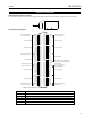
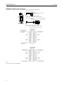
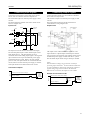
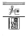
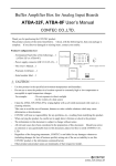
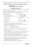
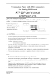
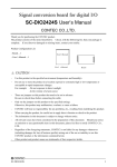
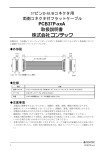
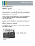
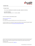
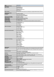
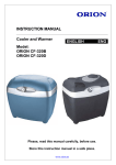
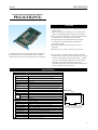
PIO-32/32L(PCI)
Ver.2.01
PCI Bus Opto-Isolated Digital I/O Board
PIO-32/32L(PCI)
Features
PIO-32/32L(PCI) performs up to 32-channel input and 32channel output.
Common power-supply configuration in 16 channel units,
capable of supporting different external power supplies.
Opto-coupler used to electrically isolated I/O signal interface
from the PCI bus, offering good noise immunity.
Four input signals can also generate interrupt requests,
Also capable of selecting the input signal edge for
generating interrupts
Digital filtering that prevents input signal noise and
chattering.
Output ability: up to 35VDC, 100mA per signal, max.
PIO-32/32L(PCI) is a PCI bus-compatible add-on interface
board designed for isolated digital input/output. Plugged in a
PCI bus expansion slot on the motherboard of a personal
computer, the board can input and output up to 32 channels.
API-PAC(W32) is the library software that provides the
commands for CONTEC hardware products in the form of
Windows standard Win32 API functions (DLL). It makes
it easy to create high-speed application software taking
advantage of the CONTEC hardware using various
programming languages that support Win32 API functions,
such as Visual Basic and Visual C/C++.
Specification
Item
Specification
Input
Type
Opto-Isolated Input (for current sinking output) (Negative logic)
Number of Channels
32 channels (4 of these 32 can be used as interrupt signal)
(16 channels with the common)
Resister
3kΩ
Current required to turn ON 3.4mA (Min.)
Current required to turn OFF 0.16mA (Max.)
Interrupts
Combine four interrupt signals to one interrupt request signal as the INTA.
Either rising edge or falling edge of input signal can generate interrupt.
Response time
1 ms (Max.)
Board size
Type
Opto-Isolated Open Collector Output (current sinking type) (Negative logic)
Number of Channels
32 channels (16 channels with the common)
Rating
Voltage
35VDC (Max.)
Current
100mA Max. per channel
Response time
1 ms (Max.)
Common
I/O address
Any 32-byte boundary
Interrupt level
1 level use/not use (select with jumper switch)
Boards in one system
Maximum of 16 boards can be install in a same system.
External power supply
12 to 24VDC (±15%)
Power consumption
5 VDC
Operating condition
0 to 50ºC, 20% to 90% (not condensing)
176.41(L )
106.68(H )
Output
[mm]
The standar d out side dimension (L ) is
t he dist ance fr om t he end of the boar d
t o t he out er sur face of t he slot cover.
300mA (Max.)
Connecting distance
50m (Typical) (depending on wiring environment)
PCI bus specification
32bit, 33MHz, 5V
Dimension (mm)
176.41 (L) x 106.68 (H)
Weight
215 g
* Data “0”and “1”correspond to the High and Low levels, respectively.
1
PIO-32/32L(PCI)
Support Software
API Function Library
The bundled CD-ROM "API Function Library Package APIPAC(W32)"
API-PAC(W32) is the library software that provides the
commands for CONTEC hardware products in the form of
Windows standard Win32 API functions (DLL).
It makes it easy to create high-speed application software
taking advantage of the CONTEC hardware using various
programming languages that support Win32 API functions,
such as Visual Basic and Visual C/C++.
Use the installed diagnosis program to check whether the
board and driver software work normally, thereby you can
confirm that they have been set up correctly.
For details, refer to the help file. The help file provides
various items of information such as "Function Reference",
"Sample Programs", and "FAQs". Use them for program
development and troubleshooting.
Ver.2.01
Accessories (Option)
Accessories (Option)
Screw Terminal : EPD-96 *1
Digital I/O 64CH Series Terminal Panel : DTP-64(PC) *1
Signal Monitor for Digital I/O(64Bits) : CM-64(PC)E *1
Screw Terminal : EPD-37 *2
Signal Monitor for Digital I/O(64Bits) : CM-32(PC)E *2
96-pin Half Pitch to 37-pin D-type (female) x 2 Connector
Converter Board: CCB-96 *3
*1: The option cable PCB37P or PCB37PS is needed.
*2: The option cable PCB37W or PCB37WS is needed.
*3: The option cable PCB37P or PCB37PS or 37-pin D-type
cable is needed.
Cable & Connector (Option)
< Operating environment >
Support OS
Windows XP, Windows 2000 Professional, Windows NT,
Windows Me/98/95
Support Language
Visual C++
Version 6.0, 5.0, 4.x, 2.0
Visual Basic Version 6.0, 5.0, 4.0
Visual C++ .NET
Visual Basic .NET
Borland C
Version 5.0, 4.5x
Borland C++ Builder 6.0, 5.0
Borland Delphi 6.0, 4.0 3.0
The newest driver and download service (http://www.contec.
com/apipac/) of difference file are also offered.
Library for digital I/O boards API-DIO(LNX)
It is free download service of the driver for Linux.
The API-DIO(LNX) is a library for controlling our digital I/O
board in Linux.
Feature
API-DIO (LNX) offers the function group for controlling our
digital I/O board by shared library and the driver of module
form.
Fundamental functions, such as input and output, interrupt,
trigger function and timer function are offered.
It configure the device to be used by the setting program
(config) and the setting file.
A configuration program outputs the setting file that makes
easy to execution environment, a driver starting script and a
stop script.
The source code for user interrupt processing is included and
used with a driver.
You can download updated driver software and differential
files as well as sample programs available in several
languages.
2
Cable & Connector (Option)
96-pin Half Pitch to 96-pin Half Pitch Shield Cable:
PCB96PS-* (1.5m, 3m, 5m)
96-pin Half Pitch to 96-pin Half Pitch Flat Cable
PCB96P-* (1.5m, 3m, 5m)
96-pin Half Pitch to 96 wires Shield Cable
PCA96PS-* (1.5m, 3m, 5m)
Product Configuration List
Product Configuration List
- Board[PIO-32/32L(PCI)] ... 1
- This User's Manual ... 1
- CD-ROM [API-PAC(W32)] ... 1
PIO-32/32L(PCI)
Ver.2.01
External Connection
Connecting the Interface Connector
To connect an external device to this board, plug the cable from the device into the interface connector (CN1) shown below.
CN1
Connector Pin Assignment
Com m on pl u s pi n f or
+6/+7 ou t pu t por t s
+7 por t (Ou t pu t )
+6 por t (Ou t pu t )
Com m on m i n us pi n for
+6/+7 out put por t s
U n con nect ed
Com m on pl u s pi n for
+4/+5 ou t pu t por t s
+5 por t (Out put )
+4 por t (Out put )
Com m on m i n us pi n for
+4/+5 out put por t s
O P 6 /7
O P 6 /7
O 77
O 76
O 75
O 74
O 73
O 72
O 71
O 70
O 67
O 66
O 65
O 64
O 63
O 62
O 61
O 60
O N 6 /7
O N 6 /7
N .C .
N .C .
N .C .
N .C .
N .C .
N .C .
N .C .
N .C .
O P 4 /5
O P 4 /5
O 57
O 56
O 55
O 54
O 53
O 52
O 51
O 50
O 47
O 46
O 45
O 44
O 43
O 42
O 41
O 40
O N 4 /5
O N 4 /5
[49]
B 48
B 47
B 46
B 45
B 44
B 43
B 42
B 41
B 40
B 39
B 38
B 37
B 36
B 35
B 34
B 33
B 32
B 31
B 30
B 29
B 28
B 27
B 26
B 25
B 24
B 23
B 22
B 21
B 20
B 19
B 18
B 17
B 16
B 15
B 14
B 13
B 12
B 11
B 10
B 09
B 08
B 07
B 06
B 05
B 04
B 03
B 02
B 01
[ 96]
[ 1]
A 48
A 47
A 46
A 45
A 44
A 43
A 42
A 41
A 40
A 39
A 38
A 37
A 36
A 35
A 34
A 33
A 32
A 31
A 30
A 29
A 28
A 27
A 26
A 25
A 24
A 23
A 22
A 21
A 20
A 19
A 18
A 17
A 16
A 15
A 14
A 13
A 12
A 11
A 10
A 09
A 08
A 07
A 06
A 05
A 04
A 03
A 02
A 01
[ 48]
I P 2 /3
I P 2 /3
I 37
I 36
I 35
I 34
I 33
I 32
I 31
I 30
I 27
I 26
I 25
I 24
I 23
I 22
I 21
I 20
N .C.
N .C.
N .C.
N .C.
N .C.
N .C.
N .C.
E XT O0
EXTI 0
N .C.
I P 0 /1
I P 0 /1
I 17
I 16
I 15
I 14
I 13
I 12
I 11
I 10
I 07
I 06
I 05
I 04
I 03 *
I 02 *
I 01 *
I 00 *
I N 0/1
I N 0/1
Com m on pl u s pi n for
+2/+3 i n pu t por t s
+3 por t (I n pu t )
+2 por t (I n pu t )
U n conn ect ed
A C K si gn al f or h an d sh ak i n g
ST B si gn al f or h an dsh ak i n g
U n conn ect ed
Com m on pl u s pi n for
+0/+1 i n pu t por t s
and h an dshak i n g
+1 por t (I n pu t )
+0 Por t (I n pu t )
Com m on m i n u s pi n for
han dsh ak i ng
*I-00 to I-03 can be used as interrupt signal.
I-00~I-37
32 input signal pins. Connect output signals from the external device to these pins.
O-40~O-77
32 output signal pins. Connect input signals from the external device to these pins.
EXTO0, EXTI0
ACK signal for handshaking, STB signal for handshaking
IP 0/1~IP 2/3
Connect the positive side of the external power supply. These pins are common to 16 input signal pins.
OP 4/5~OP 6/7
Connect the positive side of the external power supply. These pins are common to 16 output signal pins.
IN 0/1
Common minus pin for handshaking
ON 4/5~ON 6/7
Connect the negative side of the external power supply. These pins are common to 16 output signal pins.
N.C.
This pin is left unconnected.
3
PIO-32/32L(PCI)
Ver.2.01
PCB96WS and CCB-96 Signal Assignments
Optional cable connectors and their corresponding signals are shown in the figure below.
* Opt ional cable PCB96WS-* *
A
Connect or
17JE-23370-02(D8C) [mfd. by DDK ]
or equivalent
B
B48
B47
B2
B1
Connect or : PCR-E96FA [mfd. by H ONDA]
Connect or cover : PCS-E96L K PA [mfd. by H ONDA]
A48
A47
A2
A1
On-boar d connect or
name PCR-E96L M D
[mfd. by H ONDA]
* Opt ional cable PCB96PS-* * + connect or conver sion boar d CCB-96
Connect or
DCL C-J37SAF-20L 9 [mfd. by JAE] or equivalent
CCB-96
Connect or : PCR-E96FA [mfd. by H ONDA]
Connect or cover : PCS-E96L K PA [mfd. by H ONDA]
* * r epr esent s t he cabl e lengt h (1.5, 3, or 5m).
Note!
Not support signals for handshaking.
4
PIO-32/32L(PCI)
Ver.2.01
Connecting Input Signals
Connecting Output Signals
Connect the input signals to a device that can be currentdriven, such as a switch or transistor output device.
The connection requires an external power supply to feed
currents.
The board inputs the ON/OFF state of the current-driven
device as a digital value.
Input circuit
Ext er nal
Device
Boar d
VCC
5.1kΩ
3kΩ
Plus
Common
I nput
Pin
Photocoupler
Connect the output signals to a current-driven controlled
device such as a relay or LED.
The connection requires an external power supply to feed
currents.
The board controls turning on/off the current-driven
controlled device using a digital value.
Output circuit
Ext ernal
Power
Supply
DC12V
~ 24V
VCC
5.1kΩ
3kΩ
Photocoupler
I nput
Pin
The input circuit of this board is illustrated in the figure.
The on-board photocouplers isolate internal input circuits
from outside devices. The input channels are to be
connected with current sinking output signals. Driving these
opto-isolated circuits require an additional power supply
isolated from the PC system. When a 12 VDC external
power is used, each input channel will consume about 4mA
current; when a 24 VDC external power supply is selected,
each input channel will consume about 8 mA current.
Connection examples
The output circuit of this illustrated in Figure 4.6. The
output channel is a photocoupler-insulated open-collector
type (sink type). Driving these opto-isolated circuits require
an additional power supply isolated from the PC system.
The maximum output current rating is 100mA per channel.
Notes!
The board has no voltage surge protection circuits for
protecting output transistors. To drive inductive loads such
as relays and lamps by this board, consequently a measure
against voltage surge must be taken on the load side.
When the PC is turned on, all output are reset to OFF.
+ Ext er nal
I 00 (CN1 : A03pin)
Power
Supply
DC12~24V
Example of Connection to LED
Common puls for output (CN 1 : B19pin)
+
5.1k Ω
Boar d
Boar d
Common plus for input (CN1 : A19pi n)
Ext er nal
Power
Supply
DC12~24V
L ED
O40 (CN 1 : B03pin)
Common minus for out put (CN 1 : B01pin)
5
PIO-32/32L(PCI)
Ver.2.01
Connecting the Sink Type Output and Sink Output Support Input
The following example shows a connection between a sink type output (output board) and a sink output support input (input
board). Refer to this connection example when you connect such boards to each other.
Ext er nal
Power Supply
12V t o 24VDC
-
+
Out put Boar d
I nput Boar d
Common plus
for input
Common plus
for out put
Out put (Sink Type)
I nput (Sink Out put Suppor t )
Common M innus
for out put
PCI BU S
Block Diagram
AD31~AD0
C/BE3~C/BE0
CL K
FRAM E
I RDY
I DSEL
TRDY
DEVSEL
RST
I NTA
I nt er face
&
Cont r ol
Cir cuit s
I nt er rupt
Cont r ol
Cir cuit
Photocouplers
I nput Por t 0
(8ch, Gr oup0)
Photocouplers
I nput Por t 1
(8ch, Gr oup1)
Photocouplers
I nput Por t 2
(8ch, Gr oup2)
Photocouplers
I nput Por t 3
(8ch, Gr oup3)
Photocouplers
&
Transistors
Out put Por t 0
(8ch, Gr oup4)
Photocouplers
&
Transistors
Out put Por t 1
(8ch, Gr oup5)
Photocouplers
&
Transistors
Out put Por t 2
(8ch, Gr oup6)
Photocouplers
&
Transistors
Out put Por t 3
(8ch, Gr oup7)
PI O-32/32L (PCI )
6