1
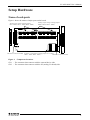
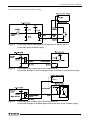
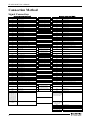
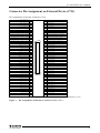
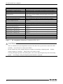
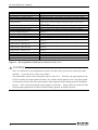
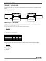
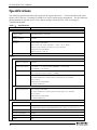
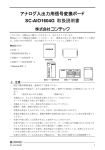
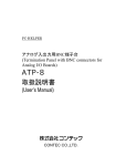
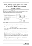
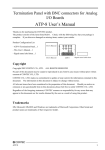
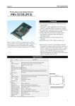
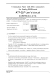
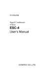
Signal conversion board for analog I/O
SC-AIO1604G User’s Manual
CONTEC CO.,LTD.
Thank you for purchasing the CONTEC product.
The product consists of the items listed below. Check, with the following list, that your package is
complete. If you discover damaged or missing items, contact your retailer.
Product Configuration List
- Board…1
User's Manual
- User’s Manual…1
User’s Manual
Board
CAUTION
-
Use this product in the specified environment (temperature and humidity).
-
Do not use or store the product in a location exposed to extremely high or low temperature or
susceptible to rapid temperature changes.
For example: - Do not exposure to direct sunlight
- In the vicinity of a heat source
-
CONTEC will bear no responsibility for any problems, etc., resulting from modifying this product.
-
When carrying the product, be careful not to apply direct vibration or shock to the product.
-
The information in this document is subject to change without notice.
-
All relevant issues have been considered in the preparation of this document. Should you notice
an omission or any questionable item in this document, please feel free to notify CONTEC CO.,
LTD.
-
Regardless of the foregoing statements, CONTEC is not liable for any damages whatsoever
(including damages for loss of business profits) arising out of the use or inability to use this
CONTEC product or the information contained herein.
-
Other product and product names are trademarks of their respective holder.
SC-AIO1604G
1
SC-AIO1604G User’s Manual
About the Product
Signal Conditioner SC Series can reduce the type and number of measurement / control board of PC
side by converting the signal and circuit being coexisted by the signal and circuit spec. when measuring
and controlling with multiple external devices.
You can easily build the system without the original circuit by using the Signal Conditioner SC Series
conversion board.
This product is a signal conversion board for a signal conditioner (signal conversion) SC Series analog
I/O. For each channel, this product can be set by using one of 6 types of range (Bipolar ±10V, ±5V,
±2.5V, Unipolar 0 - 10V, 0 - 5V, 4 - 20mA) according to the analog input / output signal on the external
device. According to the counter signal on external device, this product can be set to isolation/
non-isolation for each channel.
Features
-
Range settings for each channel are supported according to the analog signal on external
device.
According to the analog signal on external device, range settings (Bipolar ±10V, ±5V, ±2.5V, Unipolar
0 - 10V, 0 - 5V, 4 - 20mA) can be done for each channel.
In the analog signal from the external device side, all the setting ranges are converted to the voltage of
bipolar ±10V and then are output to the PC side (analog I/O board).
In the analog signal from the PC side (analog I/O board), the voltage of bipolar ±10V range is converted
to the voltage/current of setting range and then output to the external device side.
Switching the range can be done using the jumper.
-
According to the counter signal on external device, isolated/non-isolated settings can be done
for each channel.
According to the counter signal on external device, this product can be set to isolation/ non-isolation for
each channel. Counter signal to the PC (analog I/O board) side is non-isolation.
Switching the range can be done using the jumper.
CAUTION
-
Note that you cannot use AIO-163202F-PE, ADA16-32/2(PCI)F, ADA16-32/2(CB)F,
AI-1664LA-LPE, AO-1608L-LPE, AO-1616L-LPE, AD16-64(LPCI)LA, DA16-8(LPCI)L,
DA16-16(LPCI)L in the specification exceeding that of signal conditioner.
-
I/O boards by analog F, L series correspond to the up count operation and those of analog M series
correspond to the up down count operation.
2
SC-AIO1604G
SC-AIO1604G User’s Manual
Setup Hardware
Name of each parts
Figure 1 shows the names of major parts on the board.
Analog input range setting jumper
(JP1 - JP24, JP 31 - JP50, JP59 - JP62)
Analog output range setting jumper
(JP25 - JP30, JP 63 - JP68)
Interface connector (CN2) Isolation / unisolation setting jumper for counter
(JP51 - JP58, JP69 - JP76)
Interface connector (CN1)
Figure 1.
CN1
CN2
Component Locations
: The connector that connects with the external device side.
: The connector that connects with the PC (analog I/O board) side.
SC-AIO1604G
3
SC-AIO1604G User’s Manual
Setting Method
Setting the Analog Input Range
The analog input range can be set for each channel. Switching the range can be done using the jumper.
For setting the analog input range, configure the jumper according to the table below.
Analog Input
JP A
JP B
JP C
Voltage Input ±10V
(Factory setting)
1-2
short
1-2
short
1 - 5 short
2 - 6 short
1-2
short
1 - 5 short
3 - 7 short
1-2
short
2 - 6 short
2 - 6 short
1-2
short
3 - 7 short
3 - 7 short
4 - 8 short
4 - 8 short
1-5
short
1-5
short
Voltage Input ±5V
Voltage Input ±2.5V
Voltage Input 0V - 10V
Voltage Input 0V - 5V
Current Input 4mA - 20mA
2 - 3 short
Correspondences between the jumpers and channels in the above table are summarized in the table
below.
JP A
JP B
JP C
Channel 00 Channel 01 Channel 02 Channel 03 Channel 04 Channel 05 Channel 06 Channel 07
JP 1
JP 2
JP 7
JP 8
JP 13
JP 14
JP 19
JP 20
JP 3
JP 4
JP 9
JP 10
JP 15
JP 16
JP 21
JP 22
JP 5
JP 6
JP 11
JP 12
JP 17
JP 18
JP 23
JP 24
JP A
JP B
JP C
Channel 08 Channel 09 Channel 10 Channel 11 Channel 12 Channel 13 Channel 14 Channel 15
JP 31
JP 32
JP 37
JP 38
JP 43
JP 44
JP 49
JP 50
JP 33
JP 34
JP 39
JP 40
JP 45
JP 46
JP 59
JP 60
JP 35
JP 36
JP 41
JP 42
JP 47
JP 48
JP 61
JP 62
Ex.) The jumper settings in the right figure shows
the input range of the channel 0 set to ±10V.
4
SC-AIO1604G
SC-AIO1604G User’s Manual
Setting the Analog Output Range
The analog output range can be set for each channel. Switching the range can be done using the
jumper. For setting the analog output range, configure the jumper according to the table below.
Analog Output
JP A
JP B
JP C
1 - 5 short
1- 5 short
1 - 2 short
2 - 6 short
1 - 5 short
1 - 2 short
3 - 7 short
1 - 5 short
1 - 2 short
1 - 2 short
Voltage Output ±10V
(Factory setting)
Voltage Output ±5V
Voltage Output ±2.5V
Voltage Output 0V - 10V
2-6
short
2 - 6 short
3-7
short
3 - 7 short
1-2
short
4-8
short
4 - 8 short
2-3
short
Voltage Output 0V - 5V
Current Output 4mA - 20mA
Correspondences between the jumpers and channels in the above table are summarized in the table
below.
JP A
JP B
JP C
Channel 00 Channel 01 Channel 02 Channel 03
JP 25
JP 26
JP 63
JP 64
JP 27
JP 28
JP 65
JP 66
JP 29
JP 30
JP 67
JP 68
Ex.) The jumper settings in the right figure shows
the output range of the channel 0 set to ±10V.
SC-AIO1604G
5
SC-AIO1604G User’s Manual
Setting the Counter
For the counter, isolated/non-isolated connection is supported for each channel.
isolated/unisolated can be done using the jumper.
Switching between
For setting the counter, configure the jumper according to the table below.
Isolation
Unisolation
1 - 2 short
(Factory setting)
2 - 3 short
For the jumper settings that correspond to the channels, refer to the tables below.
Ensure that all of the 8 jumpers are set to the same.
Channel 00
Channel 01
JP 51
JP 55
JP 52
JP 56
JP 53
JP 57
JP 54
JP 58
JP 69
JP 73
JP 70
JP 74
JP 71
JP 75
JP 72
JP 76
Connection at the time of isolation setting
Figure 2.
Connecting counter input signal (CNT Input A0, A1, B0, B1, Z0, Z1)
(at the time of isolation setting)
Figure 3.
Connecting control output signal (CNT Output 00, 01)
(at the time of isolation setting)
6
SC-AIO1604G
SC-AIO1604G User’s Manual
Connection at the time of non-isolation setting
Figure 4.
Connecting counter input signal (CNT Input A0, A1, B0, B1, Z0, Z1)
(at the time of non-isolation setting)
Figure 5.
Connecting control output signal (CNT Output 00, 01)
(Connection Example to TTL level Input circuit at the time of non-isolation setting)
Figure 6.
Connecting control output signal (CNT Output 00, 01)
(Connection Example to isolation input circuit at the time of non-isolation setting)
SC-AIO1604G
7
SC-AIO1604G User’s Manual
Connection Method
Signal Connection
Analog I/O board side (CN2)
A48
External device side (CN1)
Analog Output 00
Range conversion circuit
A01
A46
Analog Output 01
Range conversion circuit
A03
Analog Output 01
A44
Analog Input 00
Range conversion circuit
A05
Analog Input 00
A42
Analog Input 01
Range conversion circuit
A07
Analog Input 01
A38
Analog Input 02
Range conversion circuit
A09
Analog Input 02
A36
Analog Input 03
Range conversion circuit
A11
Analog Input 03
A32
Analog Input 04
Range conversion circuit
A13
Analog Input 04
A30
Analog Input 05
Range conversion circuit
A15
Analog Input 05
A26
Analog Input 06
Range conversion circuit
A17
Analog Input 06
A24
Analog Input 07
Range conversion circuit
A19
Analog Input 07
A18
Digital Input 00
A21
Digital Input 00
A17
Digital Input 01
A22
Digital Input 01
A16
Digital Input 02
A25
Digital Input 02
A15
Digital Input 03
A26
Digital Input 03
A14
Digital Input 04
A27
Digital Input 04
A13
Digital Input 05
A28
Digital Input 05
A12
Digital Input 06
A31
A11
Digital Input 07
A32
Digital Input 07
A10
AI Control Signal OutPut00
A33
AI Control Signal OutPut00
A09
AI Control Signal OutPut01
A34
AI Control Signal OutPut01
A07
AI External Sampling Clock Input
A39
AI External Sampling Clock Input
A06
AI External Stop Trigger Input
A37
A05
AI External Start Trigger Input
A35
AI External Start Trigger Input
A04
CNT Input A0
A45
CNT Input A0
A43
CNT Input B0
A44
CNT Input Z0
A03
CNT Input B0
A02
CNT Input Z0
A01
CNT Output 00
B48
Analog Output 02
B46
Analog Output 03
B44
B42
B38
Isolation / non-isolation
conversion circuit
Isolation / non-isolation
conversion circuit
Isolation / non-isolation
conversion circuit
Analog Output 00
Digital Input 06
AI External Stop Trigger Input
B46
CNT Output 00
Range conversion circuit
B01
Analog Output 02
Range conversion circuit
B03
Analog Output 03
Analog Input 08
Range conversion circuit
B05
Analog Input 08
Analog Input 09
Range conversion circuit
B07
Analog Input 09
Analog Input 10
Range conversion circuit
B09
Analog Input 10
B36
Analog Input 11
Range conversion circuit
B11
Analog Input 11
B32
Analog Input 12
Range conversion circuit
B13
Analog Input 12
B30
Analog Input 13
Range conversion circuit
B15
Analog Input 13
B26
Analog Input 14
Range conversion circuit
B17
Analog Input 14
B24
Analog Input 15
Range conversion circuit
B19
Analog Input 15
B18
Digital Output 00
B21
Digital Output 00
B17
Digital Output 01
B22
Digital Output 01
B16
Digital Output 02
B25
Digital Output 02
B15
Digital Output 03
B26
Digital Output 03
B14
Digital Output 04
B27
Digital Output 04
B13
Digital Output 05
B28
Digital Output 05
B12
Digital Output 06
B31
B11
Digital Output 07
B32
Digital Output 07
B10
AO Control Signal OutPut00
B34
AO Control Signal OutPut00
B09
AO Control Signal OutPut01
B33
AO Control Signal OutPut01
B07
AO External Sampling Clock Input
B39
AO External Sampling Clock Input
B06
AO External Stop Trigger Input
B37
B05
AO External Start Trigger Input
B04
CNT Input A1
Isolation / non-isolation
conversion circuit
Isolation / non-isolation
conversion circuit
Isolation / non-isolation
conversion circuit
Digital Output 06
AO External Stop Trigger Input
B35
AO External Start Trigger Input
A47
CNT Input A1
A46
CNT Input B1
A48
CNT Input Z1
B45
CNT Output 01
B03
CNT Input B1
B02
CNT Input Z1
B01
CNT Output 01
A21,A22,A23,A25,
A27,A28,A29,A31,
A33,A34,A35,A37,
A39,A40,A41,A43,
A45,A47,B21,B22,
B23,B25,B27,B28,
B29,B31,B33,B34,
B35,B37,B39,B40,
B41,B43,B45,B47
A08,A19,A20,B08,
B19,B20
Analog Ground
A02,A04,A06,A08,A10,A Analog Ground
12,A14,A16,A18,A20,B0
2,B04,B06,B08,B10,B12,
B14,B16,B18,B20
Digital Ground
A23,A24,,A29,A30,A36,A Digital Ground
38,A40,B23,B24,B29,B3
0,B36,B38,B40
B44
Plus common 00
B48
B43
B47
A41,A42,B41,B42
8
Plus common 01
Minus common 00
Minus common 01
N.C.
SC-AIO1604G
SC-AIO1604G User’s Manual
Connector Pin Assignment on External Device (CN1)
Pin Assignments of Interface Connector (CN1)
Plus common 01
B48
A48
Minus common 01
B47
A47
CNT Input A1
CNT Output 00
B46
A46
CNT Input B1
CNT Output 01
B45
A45
CNT Input A0
CNT Input Z0
CNT Input Z1
Plus common 00
B44
A44
Minus common 00
B43
A43
CNT Input B0
N.C.
B42
A42
N.C.
N.C.
B41
A41
N.C.
Digital Ground
B40
A40
Digital Ground
AO External Sampling Clock Input
B39
A39
AI External Sampling Clock Input
Digital Ground
B38
A38
Digital Ground
AO External Stop Trigger Input
B37
A37
AI External Stop Trigger Input
Digital Ground
B36
A36
Digital Ground
AO External Start Trigger Input
B35
A35
AI External Start Trigger Input
AO Control Signal OutPut00
B34
A34
AI Control Signal OutPut01
AO Control Signal OutPut01
B33
A33
AI Control Signal OutPut00
Digital Output 07
B32
A32
Digital Input 07
Digital Output 06
B31
A31
Digital Input 06
Digital Ground
B30
A30
Digital Ground
Digital Ground
B29
A29
Digital Ground
Digital Output 05
B28
A28
Digital Input 05
Digital Output 04
B27
A27
Digital Input 04
Digital Output 03
B26
A26
Digital Input 03
Digital Output 02
B25
A25
Digital Input 02
Digital Ground
B24
A24
B48
[49] [1]
A48
Digital Ground
Digital Ground
B23
A23
Digital Ground
Digital Output 01
B22
A22
Digital Input 01
Digital Output 00
B21
A21
Digital Input 00
Analog Ground
B20
A20
Analog Ground
Analog Input 15
B19
A19
Analog Input 07
Analog Ground
B18
A18
Analog Ground
Analog Input 14
B17
A17
Analog Input 06
Analog Ground
B16
Analog Input 13
B15
Analog Ground
B14
Analog Input 12
B13
A01
B01
[96] [48]
A16
Analog Ground
A15
Analog Input 05
A14
Analog Ground
A13
Analog Input 04
Analog Ground
B12
A12
Analog Ground
Analog Input 11
B11
A11
Analog Input 03
Analog Ground
B10
A10
Analog Ground
Analog Input 10
B09
A09
Analog Input 02
Analog Ground
B08
A08
Analog Ground
Analog Input 09
B07
A07
Analog Input 01
Analog Ground
B06
A06
Analog Ground
Analog Input 08
B05
A05
Analog Input 00
Analog Ground
B04
A04
Analog Ground
Analog Output 03
B03
A03
Analog Output 01
Analog Ground
B02
A02
Analog Ground
Analog Output 02
B01
A01
Analog Output 00
The numbers in square brackets [ ] are pin numbers designated by HONDA TSUSHIN KOGYO CO., LTD.
Figure 7.
Pin Assignments of Interface Connector (CN1) < 1/2 >
SC-AIO1604G
9
SC-AIO1604G User’s Manual
Analog Input 00 - Analog Input 15
Analog Output - Analog Output 03
Analog Ground
Digital Input 00 - Digital Input 07
Digital Output 00 - Digital Output 07
Digital Ground
AI External Sampling Clock Input
AI External Stop Trigger Input
AI External Start Trigger Input
AI Control Signal Output00 AI Control Signal Output01
AO External Sampling Clock Input
AO External Stop Trigger Input
AO External Start Trigger Input
AO Control Signal Output00 AO Control Signal Output01
CNT Input A0 - CNT Input A1
CNT Input B0 - CNT Input B1
CNT Input Z0 - CNT Input Z1
CNT Output 00 - CNT Output 01
Plus common 00 - Plus common 01
Minus common 00 - Minus common 01
N.C.
Figure 7.
Analog input signal. The numbers correspond to channel numbers.
Analog output signal. The numbers correspond to channel numbers.
Analog ground for analog input / output signals.
Digital input signal. The numbers correspond to channel numbers.
Digital output signal. The numbers correspond to channel numbers.
Digital ground common to digital input / output signal, external trigger
input signal, external sampling clock input signal, counter input /
output signal.
External sampling clock input signal for analog input.
External trigger input signal for stopping analog input sampling.
External trigger input signal for starting analog input sampling.
Control signal for analog input. The numbers correspond to channel
numbers.
External sampling clock input signal for analog output.
External trigger input signal for stopping analog output sampling.
External trigger input signal for starting analog output sampling.
Control signal for analog output. The numbers correspond to channel
numbers.
Counter A-phase input signal. The numbers correspond to channel
numbers.
Counter B-phase input signal. The numbers correspond to channel
numbers.
Counter Z-phase input signal. The numbers correspond to channel
numbers.
Counter output signal. The numbers correspond to channel numbers.
Plus common. The numbers correspond to channel numbers.
Minus common. The numbers correspond to channel numbers.
No connection to this pin.
Pin Assignments of Interface Connector (CN1) < 2/2 >
CAUTION
-
There is a difference in pin assignments between CN1 and CN2 so you need to connect the cable
carefully. If you do not so, it may cause failure.
-
Do not connect any of the outputs and power outputs to the analog or digital ground.
connect outputs to each other. Doing either can result in a fault.
-
If analog and digital ground is shorted together, noise on the digital signals may affect the analog
signals. Accordingly, analog and digital ground should be separated.
10
Neither
SC-AIO1604G
SC-AIO1604G User’s Manual
Connector Pin Assignment on Analog I/O Board (CN2)
Pin Assignments of Interface Connector (CN2)
Analog Output 02
Analog Output 00
B48
A48
Analog Ground
B47
A47
Analog Ground
Analog Output 03
B46
A46
Analog Output 01
Analog Ground
B45
A45
Analog Ground
Analog Input 08
B44
A44
Analog Input 00
Analog Ground
B43
A43
Analog Ground
Analog Input 09
B42
A42
Analog Input 01
Analog Ground
B41
A41
Analog Ground
Analog Ground
B40
A40
Analog Ground
Analog Ground
B39
A39
Analog Ground
Analog Input 10
B38
A38
Analog Input 02
Analog Ground
B37
A37
Analog Ground
Analog Input 11
B36
A36
Analog Input 03
Analog Ground
B35
A35
Analog Ground
Analog Ground
B34
Analog Ground
B33
B48
[49] [1]
A48
A34
Analog Ground
A33
Analog Ground
B32
A32
Analog Input 04
B31
A31
Analog Ground
Analog Input 13
B30
A30
Analog Input 05
Analog Ground
B29
A29
Analog Ground
Analog Ground
B28
A28
Analog Ground
Analog Ground
B27
A27
Analog Ground
Analog Input 14
B26
A26
Analog Input 06
Analog Input 12
Analog Ground
Analog Ground
B25
A25
Analog Ground
Analog Input 15
B24
A24
Analog Input 07
Analog Ground
B23
A23
Analog Ground
Analog Ground
B22
A22
Analog Ground
Analog Ground
B21
A21
Analog Ground
Digital Ground
B20
A20
Digital Ground
Digital Ground
B19
A19
Digital Ground
Digital Output 00
B18
A18
Digital Input 00
Digital Output 01
B17
A17
Digital Input 01
Digital Output 02
B16
A16
Digital Input 02
Digital Output 03
B15
A15
Digital Input 03
Digital Output 04
B14
A14
Digital Input 04
Digital Output 05
B13
A13
Digital Input 05
Digital Output 06
B12
A12
Digital Input 06
A01
B01
[96] [48]
Digital Output 07
B11
A11
Digital Input 07
AO Control Signal OutPut00
B10
A10
AI Control Signal OutPut00
AO Control Signal OutPut01
B09
A09
AI Control Signal OutPut01
Digital Ground
B08
A08
Digital Ground
AO External Sampling Clock Input
B07
A07
AI External Sampling Clock Input
AO External Stop Trigger Input
B06
A06
AI External Stop Trigger Input
AO External Start Trigger Input
B05
A05
AI External Start Trigger Input
CNT Input A1
B04
A04
CNT Input A0
CNT Input B1
B03
A03
CNT Input B0
CNT Input Z1
B02
A02
CNT Input Z0
A01
CNT Output 00
CNT Output 01
B01
The numbers in square brackets [ ] are pin numbers designated by HONDA TSUSHIN KOGYO CO., LTD.
Figure 8.
Pin Assignments of Interface Connector (CN2) < 1/2 >
SC-AIO1604G
11
SC-AIO1604G User’s Manual
Analog Input 00 - Analog Input 15
Analog Output 00 - Analog Output 03
Analog Ground
Digital Input 00 - Digital Input 07
Digital Output 00 - Digital Output 07
Digital Ground
AI External Sampling Clock Input
AI External Stop Trigger Input
AI External Start Trigger Input
AI Control Signal Output00 AI Control Signal Output01
AO External Sampling Clock Input
AO External Stop Trigger Input
AO External Start Trigger Input
AO Control Signal Output00 AO Control Signal Output01
CNT Input A0 - CNT Input A1
CNT Input B0 - CNT Input B1
CNT Input Z0 - CNT Input Z1
CNT Output 00 - CNT Output 01
Plus common 00 - Plus common 01
Minus common 00 - Minus common 01
N.C.
Figure 8.
Analog input signal. The numbers correspond to channel numbers.
Analog output signal. The numbers correspond to channel numbers.
Analog ground for analog input / output signals.
Digital input signal. The numbers correspond to channel numbers.
Digital output signal. The numbers correspond to channel numbers.
Digital ground common to digital input / output signal, external trigger
input signal, external sampling clock input signal, counter input /
output signal.
External sampling clock input signal for analog input.
External trigger input signal for stopping analog input sampling.
External trigger input signal for starting analog input sampling.
Control signal for analog input. The numbers correspond to channel
numbers.
External sampling clock input signal for analog output.
External trigger input signal for stopping analog output sampling.
External trigger input signal for starting analog output sampling.
Control signal for analog output. The numbers correspond to channel
numbers.
Counter A-phase input signal. The numbers correspond to channel
numbers.
Counter B-phase input signal. The numbers correspond to channel
numbers.
Counter Z-phase input signal. The numbers correspond to channel
numbers.
Counter output signal. The numbers correspond to channel numbers.
Plus common. The numbers correspond to channel numbers.
Minus common. The numbers correspond to channel numbers.
No connection to this pin.
Pin Assignments of Interface Connector (CN2) < 2/2 >
CAUTION
-
There is a difference in pin assignments between CN1 and CN2 so you need to connect the cable
carefully. If you do not so, it may cause failure.
-
The signal names on the CN2 correspond to those on the CN1. Therefore, the input signals on the
CN2 are actually the output signals from the CN1, and the output signals are the CN1 input signals.
-
Avoid causing a short-circuit by connecting the input signals with the analog ground or the digital
ground. Also, avoid connecting the input signals to each other. Doing either can result in a fault.
-
Unused output signals must be short-circuited with the ground, for stable operation.
12
SC-AIO1604G
SC-AIO1604G User’s Manual
Inserting to the box for the signal conversion board
Insert this product referring to the documentation of the box for the signal conversion boards.
Board/Card Connection
Board/Card side
Cable 1
(Sold separately)
CN2
ESC-4
CN1
Cable 2
(Sold separately)
Analog Input
board
External
device side
SC-AIO1604G
Analog
card
Figure 9.
Connecting to the board / card
Correspondence Products (Optional)
Analog M series
: AIO-121601M-PCI*1
Analog F series
: AIO-163202F-PE*1, ADA16-32/2(PCI)F*1, ADA16-32/2(CB)F*2
Analog L series
: AI-1664LA-LPE*2, AD16-64(LPCI)LA*2
The user must prepare the connecting cable about a product other than the
above. For more details on signal pin assignment, refer to the manual of board
that you use.
*1
PCB96PS-0.5P, PCB96PS-1.5P optional cable is required separately.
*2
ADC-68M/96F optional cable is required separately.
Box (Optional)
Box for signal conversion board
*1
: ESC-4 *1
ESC-4 is required to use this product.
Cables (Optional)
< External device side (CN1) and analog I/O board side (CN2) >
Shield Cable with 96-Pin Half-Pitch Connectors at Both Ends
: PCB96PS-0.5P (0.5m)
: PCB96PS-1.5P (1.5m)
< External device side (CN1) >
Shield Cable with 96-Pin D-SUB Connector at One End
: PCA96PS-0.5P (0.5m)
: PCA96PS-1.5P (1.5m)
< Analog I/O board side (CN2) >
68/96-pin conversion shielded cable for analog input/output
: ADC-68M/96F (0.5m)
SC-AIO1604G
13
SC-AIO1604G User’s Manual
Signal Conversion
This product performs signal conversion as illustrated below and corresponds to several kinds of signal
sources.
Input : Using example in 4 - 20mA
Output : Using example in ±5V
Range between boards is fixed to ±10V.
I/O range with external device is set by JP.
0V analog signal
12mA analog signal
Conversion to ±10V
External device
I/O signal
5V analog signal
Conversion from ±10V
2.5V analog signal
Input Signal Conversion
Voltage to be input is fixed to ±10V so you cannot use input value as it is.
input value according to range to be used.
It is necessary to convert
You can convert input value by using the formula as illustrated below.
A=
(B + z ) y − x
20
A : Input value from external device
B : Conversion value from signal conditioner
Range to be used
±10 [V]
±5 [V]
±2.5 [V]
0 - 10 [V]
0 - 5 [V]
4 - 20 [mA]
x
10
5
2.5
0
0
0
y
20
10
5
10
5
16
z
10
10
10
10
10
15
Conversion example
Conversion of input value when you use range 4 - 20[mA] and 0[V] is input to board is as follows.
A=
(B + z )y − x
20
(0 + 15)×16 − 0
A=
20
A = 12[ mA]
14
SC-AIO1604G
SC-AIO1604G User’s Manual
Output Signal Conversion
Voltage to be output is fixed to ±10V so you cannot use output value as it is.
output value according to range to be used.
You can convert output value by using the formula as illustrated below.
B=
It is necessary to convert
( A + x )× 20 − z
y
A : Output value to be output from signal conditioner to external device
B : Output value from board to be output the output value of A
Range to be used
±10 [V]
±5 [V]
±2.5 [V]
0 - 10 [V]
0 - 5 [V]
4 - 20 [mA]
x
10
5
2.5
0
0
0
y
20
10
5
10
5
16
z
10
10
10
10
10
15
Conversion example
Conversion of output value when you use range ±5[V] and 2.5[V] is output to external device is as
follows.
B=
( A + x )× 20 − z
y
(2.5 + 5)× 20 − 10
B=
10
B = 5[V ]
Physical Dimensions
-
The (L) of the physical dimensions corresponds to the length from the outer surface of the slot cover to the outside
of the opposite slot cover.
-
The (H) of the physical dimensions corresponds to the length between the upper and the lower ends of the slot
cover.
Figure 10. Physical Dimensions
SC-AIO1604G
15
SC-AIO1604G User’s Manual
Specifications
The following specification shows the signal for the signal conversion. For more details on the other
signal, refer to the spec. of analog I/O board to be used or connector pin assignment. For the connector
pin assignment on external device (CN1) and on analog I/O board (CN2), refer to the page 8,
“Connection Method”.
Table 1.
Specifications
Item
Specification
Analog I/O
Number of input
Single-Ended Input 16 channel
channels *1
Number of output
4 channel
channels *1
I/O range
External device side (CN1) :
Bipolar ±10V, ±5V, ±2.5V, Unipolar 0 - 10V, 0 - 5V, 4 - 20mA
(Supports range settings via jumper for each channel)
Analog I/O board side (CN2) :
Bipolar is fixed to ±10V. *2
Input bandwidth
500kHz (Max.)
Counter
Counter section
Number of channels
2 channel
*1
Counter input signal
Phase-A/UP : 1 x 2 channel, Phase-B/DOWN : 1 x 2 channel,
Phase-Z/CLR : 1 x 2 channel
Response frequency
When using TTL
1MHz (Phase difference 4MHz),
When using Optocoupler isolation
Input specification
500kHz
External device side (CN1) :
Non-isolated TTL level or Optocoupler isolated input (12 - 24VDC)
(set by jumper)
Analog I/O board side (CN2) :
Non-isolated TTL level
Control output section
Output specification
External device side (CN1) :
Non-isolated TTL level or Optocoupler isolated output (12 - 24VDC)
(set by jumper)
Analog I/O board side (CN2) :
Non-isolated TTL level
Common section
Adjustment accuracy
Connector
±1mV (Max.) *3 *4
96-pin half pitch connector [F(Female)type] x 2
PCR-E96LMD+ [HONDA TSUSHIN KOGYO CO., LTD.] or equivalence to it
Operating conditions
0 - 50ºC, 20 - 80%RH (No condensation)
Current consumption
2800mA
Physical Dimensions (mm) 261(L) x 165(H)
Weight
16
340g
SC-AIO1604G
SC-AIO1604G User’s Manual
1 : The number of available channel depends on the analog input board to be used.
2 : External signal output from board is fixed to ±10V in any range.
External signal input to board is fixed to ±10V in any range.
3 : There may be maximum of ±1mV error during a full-scale use.
4 : An error approximately 0.15% of full-range may occur when operated at 0ºC or 50ºC ambient temperature.
SC-AIO1604G
17
SC-AIO1604G
User’s Manual
CONTEC CO., LTD.
February 2009 Edition
3-9-31, Himesato, Nishiyodogawa-ku, Osaka 555-0025, Japan
Japanese http://www.contec.co.jp/
English http://www.contec.com/
Chinese http://www.contec.com.cn/
No part of this document may be copied or reproduced in any form by any means without prior written
consent of CONTEC CO., LTD.
[03272009]
[02032009]
03272009_rev2
Management No.
Parts No.
A-51-630
LYJW992