1
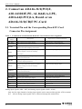
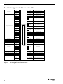
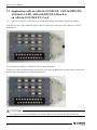
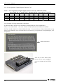
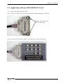
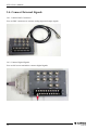
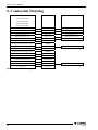
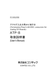
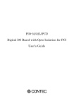
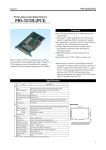
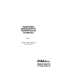
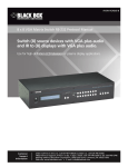
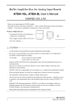
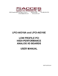
Termination Panel with BNC connectors for Analog
I/O Boards
ATP-8 User’s Manual
Thank you for purchasing the CONTEC product.
The product consists of the items listed below. Check, with the following list, that your package is
complete. If you discover damaged or missing items, contact your retailer.
Product Configuration List
- ATP-8 Termination Panel…1
User's Manual
- This User’s Manual…1
- Signal name label sheet…1
User's Manual
ATP-8
Signal name label sheet
Copyright
Copyright 2002 CONTEC CO., LTD.
ALL RIGHTS RESERVED
No part of this document may be copied or reproduced in any form by any means without prior written
consent of CONTEC CO., LTD.
CONTEC CO., LTD. makes no commitment to update or keep current the information contained in this
document. The information in this document is subject to change without notice.
All relevant issues have been considered in the preparation of this document. Should you notice an
omission or any questionable item in this document, please feel free to notify CONTEC CO., LTD.
Regardless of the foregoing statement, CONTEC assumes no responsibility for any errors that may
appear in this document nor for results obtained by the user as a result of using this product.
Trademarks
MS, Microsoft, MS-DOS and Windows are trademarks of Microsoft Corporation. Other brand and
product names are trademarks of their respective holder.
ATP-8
1
ATP-8 User’s Manual
1. About the Termination Panel
This product is a BNC connector terminal box for CONTEC’s ADA16-32/2(PCI)F, ADA16-32/2(CB)F,
AIO-163202F-PE, AI-1664LA-LPE, AD16-64(LPCI)LA, AD12-8(PM) and other analog to digital
conversion products. This terminal box eases your connection of external devices and signals.
*
For more details on this, refer to “6. Specifications”.
1.1. Features
Compact designing
With its compact designing, you can place this BNC connector terminal box at your Laptop computer.
By removing the connection cable, you can carry this box with your easily.
Easy to connect external signals
Allow you to connect analog signal through a BNC cable.
through M3 screw terminals.
All other digital signals are connected
Signal name label sheet
A name label sheet of digital signals of AD board or cards is bundled.
Sticking this name label helps you to link the external digital signals to our board or PC-Card products.
1.2. Customer Support
CONTEC provides the following support services for you to use CONTEC products more efficiently
and comfortably.
Web Site http
Japanese
English
Chinese
http://www.contec.co.jp/
http://www.contec.com/
http://www.contec.com.cn/
Latest product information
CONTEC provides up-to-date information on products.
CONTEC also provides product manuals and various technical documents in the PDF.
Note!
For product information
Contact your retailer if you have any technical question about a CONTEC product or need its price,
delivery time, or estimate information.
2
ATP-8
ATP-8 User’s Manual
1.3. Limited Three-Year Warranty
CONTEC products are warranted by CONTEC CO., LTD. to be free from defects in material and
workmanship for up to three years from the date of purchase by the original purchaser.
Repair will be free of charge only when this device is returned freight prepaid with a copy of the
original invoice and a Return Merchandise Authorization to the distributor or the CONTEC group
office, from which it was purchased.
This warranty is not applicable for scratches or normal wear, but only for the electronic circuitry and
original boards. The warranty is not applicable if the device has been tampered with or damaged
through abuse, mistreatment, neglect, or unreasonable use, or if the original invoice is not included, in
which case repairs will be considered beyond the warranty policy.
1.4. How to Obtain Service
For replacement or repair, return the device freight prepaid, with a copy of the original invoice. Please
obtain a Return Merchandise Authorization Number (RMA) from the CONTEC group office where you
purchased before returning any product.
*
No product will be accepted by CONTEC group without the RMA number.
1.5. Liability
The obligation of the warrantor is solely to repair or replace the product. In no event will the
warrantor be liable for any incidental or consequential damages due to such defect or consequences that
arise from inexperienced usage, misuse, or malfunction of this device.
ATP-8
3
ATP-8 User’s Manual
2. Connect an ADA16-32/2(PCI)F,
AIO-163202F-PE, AI-1664LA-LPE,
AD16-64(LPCI)LA, Board or an
ADA16-32/2(CB)F PC-Card
2.1. Terminal Pin and the Corresponding Board/PC-Card
Connector Pin Assignment
Table 1
Terminal Pin and the Related Board/PC-Card Connector Pin Assignment
Signal name on
Description
ATP-8
Signal name on ADA16-32/2(xx)F
AI00 - AI07
BNC connectors for analog inputs
AO00 - AO01
BNC connectors for analog outputs
Analog Output00 - Analog Output01
Trigger input signal that starts one of analog to
AI External Start Trigger Input
AISTART
digital conversion sampling transactions.
Trigger input signal that stops an on going
AISTOP
Analog Input00 - Analog Input07
AI External Stop Trigger Input
analog to digital conversion sampling
transaction.
AIEXCLK
AOSTART
Clock input signal for analog to digital
Trigger input signal that starts one of digital to analog
AO External Start Trigger Input
conversion sampling transactions.
Trigger input signal that stops an on going
AOSTOP
AI External Sampling Clock Input
conversion transactions
AO External Stop Trigger Input
digital to analog conversion sampling
transaction.
AOEXCLK
Clock input signal for digital to analog
AO External Sampling Clock Input
conversion transactions
DI00 - DI03
Digital input signals
Digital Input00 - Digital Input03
DO00 - DO03
Digital output signals
Digital Output00 - Digital Output03
CNTGATE
Counter gate control input signal
Counter Gate Control Input
CNTUPCLK
Pulse input signal for Up counting transaction
Counter Up Clock Input
CNTOUT
Counter output signal
Counter Output
DGND
Ground for all the digital signals
Digital Ground
Reserved
Reserved
Reserved
Analog input signals (AI00 - AI07) and Analog output signals (AO00 - AO01)
Only the first eight channels of analog input signals can be connected through this ATP-8 terminal
box. All two analog output signals can be connected through this terminal box.
4
ATP-8
ATP-8 User’s Manual
Digital input and output signals (DI00 - DI03, DO00 - DO03, CNT**, AI**, AO**)
For an ADA16-32/2(PCI)F, AIO-163202F-PE, AI-1664LA-LPE, AD16-64(LPCI)LA board, only
four in of its eight digital input signals, four out of its eight digital output signals, one counter of its
two counter signals and all of its trigger signals can be connected through this ATP-8 terminal box.
For an ADA16-32/2(CB)F card, all of its digital signals are supported.
Table 2
11
AISTOP
Pin Assignment of Digital Input and Output Signals (CN3)
12
13
14
AIEXCLK AOSTOP AOEXCLK
15
16
17
18
DI01
DI03
DO01
DO03
19
20
CNTGATE CNTUPCLK
1
2
3
4
5
6
7
8
9
10
AISTART
DGND
AOSTART
DGND
DI00
DI02
DO00
DO02
CNTOUT
Reserved
ATP-8
5
ATP-8 User’s Manual
2.2. Pin Assignment of Connector CN1
Non Connect
Analog Ground (for AI)
N.C.
B48
A48
AO 00
Analog Output 00
N.C.
B47
A47
AGND
Analog Ground (for AO)
N.C.
B46
A46
AO 01
Analog Output 01
N.C.
B45
A45
AGND
Analog Ground (for AO)
AGND
B44
A44
AI 00
Analog Input 00
AGND
B43
A43
AGND
Analog Ground (for AI)
AGND
B42
A42
AI 01
Analog Input 01
AGND
B41
A41
AGND
B40
A40
AGND
Analog Ground (for AI)
AGND
B39
A39
AGND
B38
A38
AI 02
Analog Input 02
AGND
B37
A37
AGND
Analog Ground (for AI)
AGND
B36
AGND
B35
AGND
B34
A36
AI 03
Analog Input 03
AGND
Analog Ground (for AI)
AGND
B33
AGND
B32
A32
AI 04
Analog Input 04
AGND
B31
A31
AGND
Analog Ground (for AI)
AGND
B30
A30
AI 05
Analog Input 05
AGND
B29
A29
AGND
B28
A28
AGND
Analog Ground (for AI)
AGND
B27
A27
AGND
B26
A26
AI 06
Analog Input 06
AGND
B25
A25
AGND
Analog Ground (for AI)
AGND
B24
A24
AGND
B23
A23
A35
B48
[49] [1]
A48
A34
A33
AI 07
Analog Input 07
AGND
Analog Ground (for AI)
Digital Ground
AGND
B22
A22
AGND
B21
A21
Digital Ground
DGND
B20
A20
DGND
Non Connect
N.C.
B19
A19
N.C.
Non Connect
Digital Output 00
DO 00
B18
A18
DI 00
Digital Input 00
Digital Output 01
DO 01
B17
A17
DI 01
Digital Input 01
Digital Output 02
DO 02
B16
A16
DI 02
Digital Input 02
Digital Output 03
DO 03
B15
A15
DI 03
Digital Input 03
N.C.
B14
N.C.
Non Connect
Non Connect
A01
B01
[96] [48]
A14
N.C.
B13
N.C.
B12
A12
N.C.
B11
A13
A11
N.C.
B10
A10
N.C.
B09
A09
Digital Ground
DGND
B08
A08
DGND
Digital Ground
AO External Sampling Clock
Input
AO EXCLK
B07
A07
AI EXCLK
AI External Sampling Clock Input
AO External Stop Trigger Input
AO STOP
B06
A06
AI STOP
AI External Stop Trigger Input
AO External Start Trigger Input
AO START
B05
A05
AI START
AI External Start Trigger Input
N.C.
B04
A04
CNT
UPCLK
Counter UP Clock Input
N.C.
B03
A03
Reserved
Reserved
N.C.
B02
A02
CNT GATE
Counter Gate Control Input
N.C.
B01
A01
CNT OUT
Counter Output
Non Connect
- [ ] shows the pin numbers specified by HONDA TSUSHIN KOGYO CO., LTD.
Figure 1
6
Pin Assignment of Connector CN1
ATP-8
ATP-8 User’s Manual
Table 3
Description of Signals (CN1)
Analog Input00 - Analog Input07
Analog input signals. The number corresponds to its channel number.
Analog Output00 - Analog Output01
Analog output signals. The number corresponds to its channel number.
Analog Ground
Ground for analog input and output signals.
AI External Start Trigger Input
AI External Stop Trigger Input
AI External Sampling Clock Input
AO External Start Trigger Input
AO External Stop Trigger Input
Trigger input signal that starts one of analog to digital conversion
sampling transactions.
Trigger input signal that stops an on going analog to digital conversion
sampling transaction.
Clock input signal for analog to digital conversion transactions
Trigger input signal that starts one of digital to analog conversion sampling
transactions.
Trigger input signal that stops an on going digital to analog conversion
sampling transaction.
AO External Sampling Clock Input
Clock input signal for digital to analog conversion transactions
Digital Input00 - Digital Input03
Digital input signals
Digital Output00 - Digital Output03
Digital output signals
Counter Gate Control Input
Counter gate control input signal
Counter Up Clock Input
Pulse input signal for Up counting transaction
Counter Output
Counter output signal
Digital Ground
Ground for all the digital signals
Reserved
Reserved
N.C.
Not connected
ATP-8
7
ATP-8 User’s Manual
2.3. Application with an ADA16-32/2(PCI)F, AIO-163202F-PE,
AI-1664LA-LPE, AD16-64(LPCI)LA Board or
an ADA16-32/2(CB)F PC-Card
2.3.1. Connect an ADA16-32/2(CB)F PC-Card and AI-1664LA-LPE, AD16-64(LPCI)LA Board
You need a Contec ADC-68M/96F option cable to connect the card to the CN1 connector of ATP-8
terminal box.
2.3.2. Connect an ADA16-32/2(PCI)F, AIO-163202F-PE Board
You need a Contec PCB96PS series option cable or a Contec PCB96P series option cable to connect the
board to the CN1 connector of ATP-8 terminal box.
CAUTION
We suggest you to use a PCB96PS-0.5m option cable to connect the board and terminal box.
8
ATP-8
ATP-8 User’s Manual
2.4. Connect External Signals
2.4.1. Connect BNC Connectors
You use BNC connectors to connect analog input and output signals.
2.4.2. Connect Digital Signals
You use M3 screw terminals to connect digital signals.
ATP-8
9
ATP-8 User’s Manual
2.4.3. Pin Assignment of Digital Signal Connector CN3
Table 4
11
AISTOP
Pin Assignment of Digital Signal Connector CN3 for ADA16-32/2(CB)F,
AIO-163202F-PE, AI-1664LA-LPE, AD16-64(LPCI)LA and ADA16-32/2(PCI)F
12
13
14
AIEXCLK AOSTOP AOEXCLK
15
16
17
18
DI01
DI03
DO01
DO03
19
20
CNTGATE CNTUPCLK
1
2
3
4
5
6
7
8
9
10
AISTART
DGND
AOSTART
DGND
DI00
DI02
DO00
DO02
CNTOUT
Reserved
2.4.4. Example of Using Signal Name Label Sheet
A name label sheet for M3 screw terminals is bundled with this ATP-8 terminal box.
There are two name labels. One is for ADA16-32/2(PCI)F board and ADA16-32/2(CB)F
PC-Card. Another label is for AD12-8(PM) PC-Card. You can stick one of these labels either on top
of the screw terminals’ cover or at front side of ATP-8 box by your preference, corresponding to your
AD product.
Name Label Sheet
Stick one of these labels either
on top of the screw terminals’
cover or at front side of ATP-8
box.
10
ATP-8
ATP-8 User’s Manual
3. Connect an AD12-8(PM) PC-Card
3.1 Terminal Pin and AD12-8(PM) PC-Card Connector Pin
Assignment
Table 5
Terminal Pin and AD12-8(PM) PC-Card Connector Pin Assignment
Signal name on
Description
ATP-8
Signal name of AD12-8(PM)
AI00 - AI07
BNC connectors for analog inputs
Analog Input0 - Analog Input7
AO00 - AO01
BNC connectors for analog outputs
Analog Output0 - Analog Output1
Trigger input signal that starts one of analog to
N/A
AISTART
digital conversion sampling transactions.
AISTOP
Trigger input signal that stops an on going
N/A
analog to digital conversion sampling
transaction.
AIEXCLK
Clock input signal for analog to digital
External Sampling Clock Input
conversion transactions
AOSTART
Trigger input signal that starts one of digital to
N/A
analog conversion sampling transactions.
AOSTOP
Trigger input signal that stops an on going
N/A
digital to analog conversion sampling
transaction.
AOEXCLK
Clock input signal for digital to analog
N/A
conversion transactions
DI00 - DI03
Digital input signals
DO00 - DO03
Digital output signals
Digital Input0 - Digital Input3
Digital Output0 - Digital Output3
CNTGATE
Counter gate control input signal
N/A
CNTUPCLK
Pulse input signal for Up counting transaction
N/A
CNTOUT
Counter output signal
N/A
DGND
Ground for all the digital signals
Digital Ground
Reserved
Reserved
N/A
Analog input and output signals (AI00 - AI07, AO00 - AO01)
Connect the eight analog input signals and two analog output signals.
ATP-8
11
ATP-8 User’s Manual
Digital input and output signals (DI00 - DI03, DO00 - DO03)
For connecting the four digital input signals, four digital output signals and a clock input signal for
analog to digital conversion transaction.
Nor other signals can be connected.
Table 6
Pin Assignment of Digital Input and Output Signals (CN3)
11
12
13
14
15
16
17
18
19
20
Reserved
AIEXCLK
Reserved
Reserved
DI01
DI03
DO01
DO03
Reserved
Reserved
1
2
3
4
5
6
7
8
9
10
Reserved
DGND
Reserved
DGND
DI00
DI02
DO00
DO02
Reserved
Reserved
3.2. Pin Assignment of Connector CN2
N.C.
Non Connect
Digital Ground
37
19
N.C.
N.C.
36
18
N.C.
N.C.
35
17
N.C.
CN2
DGND 34
37
19
16 AIEXCLK
Digital Output 2
DO02
33
DO03
Digital Output 3
Digital Output 0
DO00
32
14
DO01
Digital Output 1
Digital Input 3
DI03
31
13
DGND
Digital Ground
Digital Input 1
DI01
30
12
DI02
Digital Input 2
AGND 29
11
DI00
Digital Input 0
AGND 28
10
AO01
Analog Output 1
AGND 27
9
AO00
Analog Output 0
AGND 26
8
AI07
Analog Input 7
AGND 25
7
AI06
Analog Input 6
AGND 24
6
AI05
Analog Input 5
AGND 23
5
AI04
Analog Input 4
4
AI03
Analog Input 3
3
AI02
Analog Input 2
2
AI01
Analog Input 1
1
AI00
Analog Input 0
Analog Ground
AGND 22
20
AGND 21
AGND 20
Figure 2
Table 7
15
Non Connect
External Sampling
Clock Input
1
Pin Assignment of CN2
Description of Signals (CN2)
Analog Input0 - Analog Input7
Analog input signals. The number corresponds to its channel number.
Analog Output0 - Analog Output1
Analog output signals. The number corresponds to its channel number.
Analog Ground
Ground for analog input and output signals.
Digital Input0 - Digital Input3
Digital input signals
Digital Output0 - Digital Output3
Digital output signals
External Sampling Clock Input
Clock input signal for digital to analog conversion transactions
Digital Ground
Ground for all the digital signals
N.C.
Not connected
12
ATP-8
ATP-8 User’s Manual
3.3. Application with an AD12-8(PM) PC-Card
3.3.1. Connect the AD12-8(PM) PC-Card
First, you have to remove the nut parts from the AD12-8(PM) bundled cable, CB-37FS.
Remove the nut parts from
the CB-37FS cable
Then, you connect the CB-37FS cable to CN2 connector of ATP-8 terminal box.
ATP-8
13
ATP-8 User’s Manual
3.4. Connect External Signals
3.4.1. Connect BNC Connectors
You use BNC connectors to connect analog input and output signals.
3.4.2. Connect Digital Signals
You use M3 screw terminals to connect digital signals.
14
ATP-8
ATP-8 User’s Manual
3.4.3. Pin Assignment of Digital Signal Connector CN3.
Table 8
Pin Assignment of Digital Signal Connector CN3 for AD12-8(PM)
11
12
13
14
15
16
17
18
19
20
Reserved
AIEXCLK
Reserved
Reserved
DI01
DI03
DO01
DO03
Reserved
Reserved
1
2
3
4
5
6
7
8
9
10
Reserved
DGND
Reserved
DGND
DI00
DI02
DO00
DO02
Reserved
Reserved
3.4.4. Example of Using Signal Name Label Sheet
A name label sheet for M3 screw terminals is bundled with this ATP-8 terminal box.
There are two name labels. One is for ADA16-32/2(PCI)F board and ADA16-32/2(CB)F PC-Card.
Another label is for AD12-8(PM) PC-Card.
You can stick one of these labels either on top of the screw terminals’ cover or at front side of ATP-8
box by your preference, corresponding to your AD product.
Name Label Sheet
Stick one of these labels either on
top of the screw terminals’ cover
or at front side of ATP-8 box.
ATP-8
15
ATP-8 User’s Manual
4. Connection Drawing
ADA16-32/2(PCI)F
ATP-8
AD12-8(PM)
AIO-163202F-PE
AI-1664LA-LPE
AD16-64(LPCI)LA
ADA16-32/2(CB)F
AI00 - 07
Analog Input 0 - 7
Analog Output 00 - 01
AO00 - 01
Analog Output 0 - 1
Digital Input 00 - 03
DI00 - 03
Digital Input 0 - 3
Digital Output 00 - 03
DO00 - 03
Digital Output 0 - 3
Analog Ground
Analog Ground
Analog Ground
AI External Start Trigger Input
AISTART
AI External Stop Trigger Input
AISTOP
AI External Sampling Clock Input
AIEXCLK
AO External Start Trigger Input
AOSTART
AO External Stop Trigger Input
AOSTOP
AO External Sampling Clock Input
AOEXCLK
Counter Gate Control Input
CNTGATE
Counter Up Clock Input
CNTUPCLK
Counter Output
CNTOUT
Figure 3
16
Analog Input 00 - 07
Digital Ground
DGND
Reserved
Reserved
External Sampling Clock Input
Digital Ground
Connection Drawing
ATP-8
ATP-8 User’s Manual
88
5. Dimensions and Connector Layout
5
Figure 4
ATP-8
120
4
18.6
22
2.2
Dimensions and Connector Layout
17
ATP-8 User’s Manual
6. Specifications
Table 9
Specifications of ATP-8
Items
Specification
Supported Products
AIO-163202F-PE、ADA16-32/2(PCI)F、ADA16-32/2(CB)F、
Analog Input
8ch (BNC connector, AI00 - AI07)
AI-1664LA-LPE、AD16-64(LPCI)LA、AD12-8(PM)
Analog Output
2ch (BNC connector, AO00 - AO01)
Digital Input
4channels (Screw terminals, DI00 - DI03)
Digital Output
4channels (Screw terminals, DI00 - DI03)
Counter input and output
1ch (Screw terminals, CNTUP, CNTCLK, CNTOUT)
Operating Conditions
0 - 50ºC,
Dimensions (mm)
120(W)×40.6(D)×88(H) (Not include the height of screw terminal
10 - 90%RH (no condensation)
block and rubber feet)
420g
Weight
Table 10
Specification of Interface Connector CN1
AIO-163202F-PE、ADA16-32/2(PCI)F、ADA16-32/2(CB)F、
Support products
AI-1664LA-LPE、AD16-64(LPCI)LA
Type of Connector
PCR-E96LMD
Type of mating connector
PCS-E96LKPA
Connecting Cable
ADA16-32/2(PCI)F, AIO-163202F-PE : PCB96-**PS,
PCB96-**P(Option)
ADA16-32/2(CB)F, AI-1664LA-LPE, AD16-64(LPCI)LA :
ADC-68M/96F(Option)
Table 11
Specification of Interface Connector CN2
Support products
AD12-8(PM)
Type of Connector
37pin Female D-SUB Connector
Nut Parts
#4-40UNC Screws Nuts
Type of mating connector
37pin Male D-SUB Connector
Connecting Cable
AD12-8(PM) : PC-Card Bundled cable
Table 12
Specification of Terminal Block
Terminal
Screw type
M3
Suitable Y-type terminal C3A mfd by JST Mfg. Co., Ltd.
Dimension of
Y-type
terminal
[mm]
6.4
5.6
19
8.8
3.2
Dimensions
of Terminal
[mm]
OBU-553-20P mfd by Osada
11.1
15.8
7.62
A-46-637
LYBN133
05092008_rev4 [08232002]
18
ATP-8