1
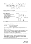
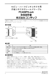
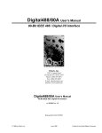
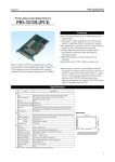
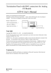
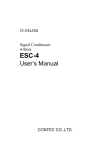
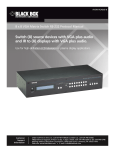
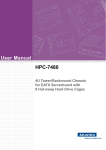
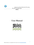
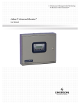
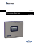
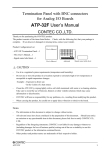
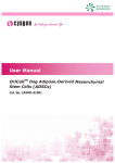
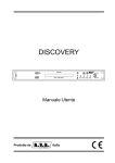
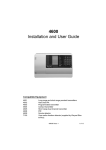
Signal conversion board for digital I/O
SC-DIO2424S User’s Manual
CONTEC CO.,LTD.
Thank you for purchasing the CONTEC product.
The product consists of the items listed below. Check, with the following list, that your package is
complete. If you discover damaged or missing items, contact your retailer.
Product Configuration List
- Board…1
User's Manual
- User’s Manual…1
User’s Manual
Board
CAUTION
-
Use this product in the specified environment (temperature and humidity).
-
Do not use or store the product in a location exposed to extremely high or low temperature or
susceptible to rapid temperature changes.
For example: - Do not exposure to direct sunlight
- In the vicinity of a heat source
-
There are jumpers on this product that need to be set in advance.
Be sure to check these before connecting the cable.
-
Only set the jumpers on this product to the specified settings.
Otherwise, this product may malfunction, overheat, or cause a failure.
-
CONTEC will bear no responsibility for any problems, etc., resulting from modifying this product.
-
When carrying the product, be careful not to apply direct vibration or shock to the product.
-
The information in this document is subject to change without notice.
-
All relevant issues have been considered in the preparation of this document. Should you notice
an omission or any questionable item in this document, please feel free to notify CONTEC CO.,
LTD.
-
Regardless of the foregoing statements, CONTEC is not liable for any damages whatsoever
(including damages for loss of business profits) arising out of the use or inability to use this
CONTEC product or the information contained herein.
-
Other product and product names are trademarks of their respective holder.
SC-DIO2424S
1
SC-DIO2424S User’s Manual
About the Product
Signal Conditioner SC Series can reduce the type and number of measurement / control board of PC
side by converting the signal and circuit being coexisted by the signal and circuit spec. when measuring
and controlling with multiple external devices.
You can easily build the system without the original circuit by using the Signal Conditioner SC Series
conversion board.
This product is a signal conversion board for the Signal Conditioner (signal conversion) SC Series
digital I/O. You can convert the digital input / output signal on the external device (12 - 24VDC) into
TTL level signal (5VDC) and input / output to / from the PC (digital I/O board). As for the output 24
channels on the external device, current sink / source is set with jumpers in 8 channels and the input 24
channels on the external device corresponds to both the current sink and source (1 common in 8
channels).
Features
-
Output 24 channels on the external device can set the current sink / source in 8 channels.
Output 24 channels on the external device can set the current sink / source in 8 channels in accordance
with the external device. Switching the current sink / source can be done using the jumper.
-
Input 24 channels on the external device corresponds to both the current sink and source
(1 common in 8 channels).
Digital input on the external device corresponds to both the current sink and source
(1 common in 8 channels).
-
Output circuits from conversion board to external device include zener diodes for surge
voltage protection and poly-switches for overcurrent protection.
Zener diodes are connected to the output circuits from conversion board to external device to protect
against surge voltages. Similarly, polyswitches are fitted to each group of 8 channels outputs for
over-current protection. The output rating is 100mA at a maximum of 35VDC per ch.
CAUTION
The digital I/O board to be connected with this product should be set to 24 channels digital inputs
(A00 - A48) and 24 channels digital outputs (B00 - B48).
Using it with other settings will result in malfunction, overheating, or failure.
2
SC-DIO2424S
SC-DIO2424S User’s Manual
Setup Hardware
Name of each parts
Figure 1 shows the names of major parts on the board.
Source/sink setting jumper (JP1 - JP48)
Interface connector (CN2)
Figure 1.
CN1
CN2
Interface connector (CN1)
Component Locations
: The connector that connects with the external device side.
: The connector that connects with the PC (digital I/O board) side.
SC-DIO2424S
3
SC-DIO2424S User’s Manual
Setting Method
Setting method of current sink / source
Setting the current sink / source is different in the way of output and input. In case of the output,
setting can be done switching the jumpers and the input, you do not have to set it. 1 common in 8
channels
For setting the current sink / source, configure the jumper according to the table below.
Source
Sink
1 - 2 short
(Factory setting)
2 - 3 short
Configure the following corresponding jumpers as indicated in the table above.
16 jumpers are set to the same.
Digital Output 00 Digital Output 07
JP1
JP7
JP13
JP19
JP25
JP31
JP37
JP2
JP8
JP14
JP20
JP26
JP32
JP38
JP44
Digital Output 08 Digital Output 15
JP3
JP9
JP15
JP21
JP27
JP33
JP39
JP45
JP4
JP10
JP16
JP22
JP28
JP34
JP40
JP46
Digital Output 16 Digital Output 23
JP5
JP11
JP17
JP23
JP29
JP35
JP41
JP47
JP6
JP12
JP18
JP24
JP30
JP36
JP42
JP48
Figure 2.
4
Ensure that all of the
JP43
Setting method of current sink / source
SC-DIO2424S
SC-DIO2424S User’s Manual
Connect a Board/Card
Connector Pin Assignment on External Device (CN1)
Pin Assignments of Interface Connector (CN1)
N.C
B48
A48
N.C
N.C
B47
A47
N.C
N.C
B46
A46
N.C
N.C
B45
A45
N.C
Output minus common 2
B44
A44
N.C
Output minus common 2
B43
A43
N.C
Digital Output 23
B42
A42
Digital Input 23
Digital Output 22
B41
A41
Digital Input 22
Digital Output 21
B40
A40
Digital Input 21
Digital Output 20
B39
A39
Digital Input 20
Digital Output 19
B38
A38
Digital Input 19
Digital Output 18
B37
A37
Digital Input 18
Digital Output 17
B36
A36
Digital Input 17
Digital Output 16
B35
A35
Digital Input 16
Output plus common 2
B34
Output plus common 2
B33
A33
Input common 2
N.C
B32
A32
N.C
N.C
B31
A31
N.C
N.C
B48
[49] [1]
A48
A34
Input common 2
B30
A30
N.C
N.C
B29
A29
N.C
Output minus common 1
B28
A28
Output minus common 1
B27
A27
N.C
Digital Output 15
B26
A26
Digital Input 15
Digital Output 14
B25
A25
Digital Input 14
Digital Output 13
B24
A24
Digital Input 13
Digital Output 12
B23
A23
Digital Input 12
Digital Output 11
B22
A22
Digital Input 11
Digital Output 10
B21
A21
Digital Input 10
Digital Output 09
B20
A20
Digital Input 09
N.C
Digital Output 08
B19
A19
Digital Input 08
Output plus common 1
B18
A18
Input common 1
Output plus common 1
B17
A17
Input common 1
N.C
B16
A16
N.C
N.C
B15
A15
N.C
N.C
B14
A14
N.C
N.C
B13
A13
N.C
Output minus common 0
B12
A12
N.C
Output minus common 0
B11
A11
N.C
Digital Output 07
B10
A10
Digital Input 07
Digital Output 06
B09
A09
Digital Input 06
Digital Output 05
B08
A08
Digital Input 05
Digital Output 04
B07
A07
Digital Input 04
Digital Output 03
B06
A06
Digital Input 03
Digital Output 02
B05
A05
Digital Input 02
Digital Output 01
B04
A04
Digital Input 01
Digital Output 00
B03
A03
Digital Input 00
Output plus common 0
B02
A02
Input common 0
Output plus common 1
B01
A01
Input common 0
A01
B01
[96] [48]
The numbers in square brackets [ ] are pin numbers designated by HONDA TSUSHIN KOGYO CO., LTD.
Figure 3.
Pin Assignments of Interface Connector (CN1)
SC-DIO2424S
<1/2>
5
SC-DIO2424S User’s Manual
Digital Input 00 - Digital Input 23
Digital Output 00 - Digital Output 23
Input common 0 - Input common 2
Output plus common 00 - Output plus
common 02
Output minus common 00 - Output
minus common 02
N.C.
Figure 3.
Digital input signal. The numbers correspond to input signal numbers.
Digital output signal. The numbers correspond to output signal
numbers.
Input common. They are common to the 8 channels each.
Output plus common.
They are common to the 8 channels each.
Output minus common.
They are common to the 8 channels each.
No connection to this pin.
Pin Assignments of Interface Connector (CN1) < 2/2 >
CAUTION
-
There is a difference in pin assignments between CN1 and CN2 so you need to connect the cable
carefully. If you do not so, it may cause failure.
-
Avoid causing a short-circuit by connecting the outputs with any of the common channels.
do not connect the outputs to each other.
Otherwise, this product may cause a failure.
6
Also,
SC-DIO2424S
SC-DIO2424S User’s Manual
Connector Pin Assignment on Digital I/O Board (CN2)
Pin Assignments of Interface Connector (CN2)
Digital Output 23
Digital Input 23
B48
A48
Digital Ground
B47
A47
Digital Ground
Digital Output 22
B46
A46
Digital Input 22
Digital Ground
B45
A45
Digital Ground
Digital Output 21
B44
A44
Digital Input 21
Digital Ground
B43
A43
Digital Ground
Digital Output 20
B42
A42
Digital Input 20
Digital Ground
B41
A41
Digital Ground
Digital Output 19
B40
A40
Digital Input 19
Digital Ground
B39
A39
Digital Ground
Digital Output 18
B38
A38
Digital Input 18
Digital Ground
B37
A37
Digital Ground
Digital Output 17
B36
A36
Digital Input 17
Digital Ground
B35
Digital Output 16
B34
B48
[49] [1]
A48
A35
Digital Ground
A34
Digital Input 16
Digital Ground
B33
A33
Digital Ground
Digital Output 15
B32
A32
Digital Input 15
Digital Ground
B31
A31
Digital Ground
Digital Output 14
B30
A30
Digital Input 14
Digital Ground
B29
A29
Digital Ground
Digital Output 13
B28
A28
Digital Input 13
Digital Ground
B27
A27
Digital Ground
Digital Output 12
B26
A26
Digital Input 12
Digital Ground
B25
A25
Digital Ground
Digital Output 11
B24
A24
Digital Input 11
Digital Ground
B23
A23
Digital Ground
Digital Output 10
B22
A22
Digital Input 10
Digital Ground
B21
A21
Digital Ground
Digital Output 09
B20
A20
Digital Input 09
Digital Ground
B19
A19
Digital Ground
Digital Output08
B18
A18
Digital Input 08
Digital Ground
B17
A17
Digital Ground
Digital Output 07
B16
A16
Digital Input 07
Digital Ground
B15
Digital Output 06
B14
Digital Ground
B13
A13
Digital Ground
Digital Output 05
B12
A12
Digital Input 05
A01
B01
[96] [48]
A15
Digital Ground
A14
Digital Input 06
Digital Ground
B11
A11
Digital Ground
Digital Output 04
B10
A10
Digital Input 04
Digital Ground
B09
A09
Digital Ground
Digital Output 03
B08
A08
Digital Input 03
Digital Ground
B07
A07
Digital Ground
Digital Output 02
B06
A06
Digital Input 02
Digital Ground
B05
A05
Digital Ground
Digital Output 01
B04
A04
Digital Input 01
Digital Ground
B03
A03
Digital Ground
Digital Output 00
B02
A02
Digital Input 00
A01
Digital Ground
Digital Ground
B01
The numbers in square brackets [ ] are pin numbers designated by HONDA TSUSHIN KOGYO CO., LTD.
Figure 4.
Pin Assignments of Interface Connector (CN2) < 1/2 >
Digital Input 00 - Digital Input 23
Digital Output 00 - Digital Output 23
Digital Ground
Figure 4.
Digital input signal. The numbers correspond to input signal
numbers.
Digital output signal. The numbers correspond to output signal
numbers.
Digital ground for digital I/O signal.
Pin Assignments of Interface Connector (CN2) < 2/2 >
SC-DIO2424S
7
SC-DIO2424S User’s Manual
CAUTION
-
There is a difference in pin assignments between CN1 and CN2 so you need to connect the cable
carefully. If you do not so, it may cause failure.
-
The signal names on the CN2 correspond to those on the CN1. Therefore, the input signals on the
CN2 are actually the output signals from the CN1, and the output signals are the CN1 input signals.
-
The digital I/O board to be connected with this product should be set to 24 channels digital inputs
(A00 - A48) and 24 channels digital outputs (B00 - B48).
Otherwise, this product may malfunction, overheat, or cause a failure.
-
The output must not be short-circuited with the digital ground.
each other. Otherwise, this product may cause a failure.
Also, do not connect the outputs to
Inserting to the box for the signal conversion board
Insert this product referring to the documentation of the box for the signal conversion boards.
Board/Card Connection
CN2
ESC-4
Cable 1
(Sold separately)
8
Cable 2
(Sold separately)
External
device side
Digital I/O board
Figure 5.
CN1
SC-DIO2424S
Connecting to the board
SC-DIO2424S
SC-DIO2424S User’s Manual
Connecting Input Signals
Connect the input signals to a device which can be current-driven, such as a switch or transistor output
device.
The connection requires an external power supply to feed currents.
This product inputs the ON/OFF state of the current-driven device as a digital value.
Input Circuit
< Corresponding to the current sink output >
< Corresponding to the current source output >
Figure 6.
Input Circuit
The input circuits of interface blocks of this product are illustrated in figure 6. 1 common in 8
channels. The signal inputs are isolated by Optocoupler (Corresponding to both of current sink and
source outputs). This product therefore requires an external power supply to drive the inputs. The
power capacity required for driving each input channel is about 4 mA (with the 12 - 24 VDC setting).
SC-DIO2424S
9
SC-DIO2424S User’s Manual
Connection Example of External Device
< Corresponding to current sink output >
SC-DIO2424S
Optocoupler
Input common
Input
Sync type
output
External power
supply
12 - 24VDC
When the input is “low level”, the corresponding bit contains 1.
When the input is “high level”, by contrast, the corresponding bit contains 0.
Figure 7.
Connecting the input to the sink type output
< Corresponding to current source output >
SC-DIO2424S
Input
Optocoupler
Source type
output
External power
supply
12 - 24VDC
Input common
When the input is “low level”, the corresponding bit contains 0.
When the input is “high level”, by contrast, the corresponding bit contains 1.
Figure 8.
10
Connecting the input to the source type output
SC-DIO2424S
SC-DIO2424S User’s Manual
Connecting Output Signals
Connect the output signals to a current-driven controlled device such as a relay or LED.
The connection requires an external power supply to feed currents.
This product controls turning on/off the current-driven controlled device using a digital value.
Output Circuit
< Current sink output >
< Current source output >
Figure 9.
Output Circuit
SC-DIO2424S
11
SC-DIO2424S User’s Manual
The output circuits of interface blocks of this product are illustrated in figure 9. 1 common in 8
channels. The signal output section is an Optocoupler isolated output and according to the external
device, current sink / source output is set with jumpers. Driving the output section requires an external
power supply (12 - 24VDC) separately. The rated output current per channel is Max. 100mA.
A zener diode is connected to the output transistor for protection from surge voltages.
A PolySwitch-based overcurrent protector is provided for every 8 output transistors. When the
overcurrent protector works, the output section of this product is temporarily disabled. If this is the
case, turn of the power to the PC and the external power supply and wait for a few minutes, then turn
them on back.
CAUTION
When the PC is turned on, all output are reset to OFF.
Connection to the LED
< Current sink output >
When 1 is output to a relevant bit, the corresponding LED is comes on.
When 0 is output to a relevant bit, by contrast, the corresponding LED is goes out.
Figure 10.
An Example to use Digital Output 00
< Current sink output >
< Current source output >
When 1 is output to a relevant bit, the corresponding LED is comes on.
When 0 is output to a relevant bit, by contrast, the corresponding LED is goes out.
Figure 11.
12
An Example to use Digital Output 00
< Current source output >
SC-DIO2424S
SC-DIO2424S User’s Manual
Correspondence Products (Optional)
DIO-48D-PE*1, DIO-48D-LPE*2, DIO-48D2-PCI*1, PIO-48D(PCI)*1, PIO-48D(LPCI)H*2,
PIO-48D(CB)H*2
*1 PCB96PS-0.5P, PCB96PS-1.5P optional cable is required separately.
*2 DIO-68M/96F optional cable is required separately.
Box (Optional)
Box for signal conversion board
*1
: ESC-4 *1
ESC-4 is required to use this product.
Cables (Optional)
< External device side (CN1) and digital I/O board side (CN2) >
Shield Cable with 96-Pin Half-Pitch Connectors at both Ends
: PCB96PS-0.5P (0.5m) *1
: PCB96PS-1.5P (1.5m) *1
: PCB96PS-3P (3m) *1,
: PCB96PS-5P (5m) *1
< External device side (CN1) >
Shield Cable with One 96-Pin Half-Pitch Connector
: PCA96PS-0.5P (0.5m)
: PCA96PS-1.5P (1.5m)
: PCA96PS-3P (3m)
: PCA96PS-5P (5m)
< Digital I/O board side (CN2) >
Shielded Cable for CardBusDigital I/O Card
: DIO-68M/96F (0.5m)
*1 As for the cable to be connected to the digital I/O side (CN2), use one wiithin 1.5 m.
Physical Dimensions
-
The (L) of the physical dimensions corresponds to the length from the outer surface of the slot cover to the outside
of the opposite slot cover.
-
The (H) of the physical dimensions corresponds to the length between the upper and the lower ends of the slot
cover.
Figure 12. Physical Dimensions
SC-DIO2424S
13
SC-DIO2424S User’s Manual
Specifications
Table 1.
Specifications
Item
Specification
External device side (CN1)
Digital input spec.
Digital output spec.
Optocoupler isolated input 24 channel
(Corresponding to current sink / current source, 12 - 24VDC,
1 common in 8 channels)
Corresponding to current sink output : negative logic *1
Corresponding to current source output : positive logic *2
Input resistance : 4.7kΩ
Input ON current : 3.1mA or more
Input OFF current : 1.0mA or less
Optocoupler isolated output 24 channel
(Current sink (open-collector) / current source is set with jumper, 12 - 24VDC,
1 common in 8 channels)
Current sink output : negative logic *1
Current source output : positive logic *2
Output rating : Max. 35V 100mA (per ch)
Digital I/O board side (CN2) *4
Board input spec.
Unisolated TTL level (Positive logic)
Board output spec.
Unisolated TTL level (Positive logic)
Common section
Response time
200μsec (Max.) *3
External power supply
12 - 24VDC (±10%)
Connector
96-pin half pitch connector [F(Female)type] x 2
PCR-E96LMD+ [HONDA TSUSHIN KOGYO CO., LTD.] or equivalence to it
Operating conditions
0 - 50ºC, 20 - 80%RH (No condensation)
Allowable distance of
Approx. 50m (depending on wiring environment)
signal extension
Current consumption
5VDC 150mA
Physical Dimensions
(mm)
261(L) x 165(H) (No protrusions)
Weight
260g
*1:
Data “0” and “1” correspond to the High and Low levels, respectively.
*2:
Data “1” and “0” correspond to the High and Low levels, respectively.
*3:
There will be 200μsec of delay at maximum when a signal passes through this product.
*4:
The digital I/O board to be connected with this product should be set to 24 channels digital inputs (A00 - A48) and
24 channels digital outputs (B00 - B48).
14
SC-DIO2424S
SC-DIO2424S User’s Manual
SC-DIO2424S
15
SC-DIO2424S
User’s Manual
CONTEC CO., LTD.
February 2009 Edition
3-9-31, Himesato, Nishiyodogawa-ku, Osaka 555-0025, Japan
Japanese http://www.contec.co.jp/
English http://www.contec.com/
Chinese http://www.contec.com.cn/
No part of this document may be copied or reproduced in any form by any means without prior written
consent of CONTEC CO., LTD.
[03272009]
[01292009]
[03272009_rev2]
Management No.
Parts No.
A-51-632
LYJX022