1
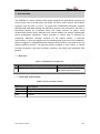
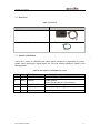
GMT200 User manual
GSM/GPRS/GPS Tracker
GMT200
User Manual
TRACGMT200UM001
Revision: 1.00
TRACGMT200UM001
http://www.queclink.com
[email protected]
GMT200 User Manual
Document Title
GMT200 User Manual
Version
1.00
Date
2014-05-20
Status
Release
Document Control ID
TRACGMT200UM001
General Notes
Queclink offers this information as a service to its customers, to support application and
engineering efforts that use the products designed by Queclink. The information provided is
based upon requirements specifically provided to Queclink by the customers. Queclink has
not undertaken any independent search for additional relevant information, including any
information that may be in the customer’s possession. Furthermore, system validation of this
product designed by Queclink within a larger electronic system remains the responsibility of
the customer or the customer’s system integrator. All specifications supplied herein are
subject to change.
k
n
i
l
l
c
a
i
t
e
n
u
Q fide
n
o
C
Copyright
This document contains proprietary technical information which is the property of Queclink.
Copying of this document and giving it to others and the using or communication of the
contents thereof, are forbidden without express authority. Offenders are liable to the payment
of damages. All rights reserved in the event of grant of a patent or the registration of a utility
model or design. All specification supplied herein are subject to change without notice at any
time.
Copyright © Queclink Wireless Solutions Co., Ltd. 2014
TRACGMT200UM001
-2-
GMT200 User Manual
Contents
1. Introduction ................................................................................................................................... 7
1.1. Reference............................................................................................................................. 7
1.2. Terms and Abbreviations ..................................................................................................... 7
2. Product Overview ......................................................................................................................... 8
2.1. Appearance .......................................................................................................................... 8
2.2. Parts List.............................................................................................................................. 9
2.3. Interface Definition ............................................................................................................. 9
3. Get Started................................................................................................................................... 10
3.1. Install a SIM Card ............................................................................................................. 10
3.2. Switch the Device on/off ................................................................................................... 10
3.3. Reset Key .......................................................................................................................... 11
3.4. USB Connector ................................................................................................................. 11
3.5. Power Connection ............................................................................................................. 11
3.6. Ignition Detection.............................................................................................................. 12
3.7. Digital Input ...................................................................................................................... 12
3.8. Digital Output.................................................................................................................... 13
3.9. Device Status LED ............................................................................................................ 14
k
n
i
l
l
c
a
i
t
e
n
u
Q fide
n
o
C
TRACGMT200UM001
-3-
GMT200 User Manual
Table Index
TABLE 1: GMT200 PROTOCOL REFERENCE .................................................................................... 7
TABLE 2: TERMS AND ABBREVIATIONS.......................................................................................... 7
TABLE 3: PARTS LIST ........................................................................................................................... 9
TABLE 4: DESCRIPTION OF GMT200 USER CABLE........................................................................ 9
TABLE 5: ELECTRICAL CHARACTERISTICS OF IGNITION DETECTION ................................. 12
TABLE 6: ELECTRICAL CHARACTERISTICS OF THE DIGITAL INPUTS ................................... 12
TABLE 8: DEFINITION OF DEVICE STATUS AND LED ................................................................. 15
k
n
i
l
l
c
a
i
t
e
n
u
Q fide
n
o
C
TRACGMT200UM001
-4-
GMT200 User Manual
Figure Index
FIGURE 1.
APPEARANCE OF GMT200 ......................................................................................... 8
FIGURE 2.
SIM CARD INSTALLATION ....................................................................................... 10
FIGURE 3.
TYPICAL POWER CONNECTION............................................................................. 11
FIGURE 4.
TYPICAL IGNITION DETECTION ............................................................................ 12
FIGURE 5.
TYPICAL DIGITAL INPUT CONNECTION .............................................................. 13
FIGURE 6.
TYPICAL CONNECTION WITH RELAY .................................................................. 13
FIGURE 7.
GMT200 LED ON THE CASE ..................................................................................... 14
k
n
i
l
l
c
a
i
t
e
n
u
Q fide
n
o
C
TRACGMT200UM001
-5-
GMT200 User Manual
Revision History
Revision
Date
Author
Description of change
V1.00
2014-05-20
Super
Initial
k
n
i
l
l
c
a
i
t
e
n
u
Q fide
n
o
C
TRACGMT200UM001
-6-
GMT200 User Manual
1. Introduction
The GMT200 is a water resistant GPS tracker designed for applications requiring low
current drain such as motorcycles and boats. Its built-in GPS receiver has superior
sensitivity and fast time to first fix. Its quad band GPRS/GSM subsystem supports
850/900/1800/1900 MHz allowing the GMT200's location to be monitored in real time or
periodically tracked by a backend server and mobile devices. Its built-in 3-axis
accelerometer allows motion detection and extends battery life through sophisticated
power management algorithms. Further reduction in current drain is achieved by
configuring alternative recharge schemes for the internal battery. It measures
70mm*46mm*17.5mm and weighs only 65g, allowing easier and more covert installation.
System integration is straightforward as complete documentation is provided for the full
featured @Track protocol. The @Track protocol supports a wide variety of reports
including emergency, geo-fence boundary crossings, low battery and scheduled GPS
position.
k
n
i
l
l
c
a
i
t
e
n
u
Q fide
n
o
C
1.1. Reference
Table 1: GMT200 Protocol Reference
SN
Document name
Remark
[1]
GMT200 @Track Air Interface Protocol
The air protocol interface between
GMT200 and backend server.
1.2. Terms and Abbreviations
Table 2: Terms and Abbreviations
Abbreviation
Description
DIN
Digital Input
DOUT
GND
Digital Output
Ground
TRACGMT200UM001
-10-
GMT200 User Manual
2. Product Overview
2.1. Appearance
k
n
i
l
l
c
a
i
t
e
n
u
Q fide
n
o
C
Figure 1. Appearance of GMT200
TRACGMT200UM001
-10-
GMT200 User Manual
2.2. Parts List
Table 3: Parts List
Name
Picture
GMT200 Locator
k
n
i
l
l
c
a
i
t
e
n
u
Q fide
n
o
C
DATA_CABLE_M (Optional)
2.3. Interface Definition
There are 5 wires on GMT200 user cable which contains the connection for power,
ignition input, digital input, digital output, etc. The user cable’s definition is shown in the
following table.
Table 4: Description of GMT200 User Cable
Index Colour
Description
Comment
1
Red
Power
External DC power input, 8-32V
Black
Ground
System ground
(connect to the vehicle’s frame directly)
White
Ignition
Ignition input, positive trigger
Blue
Digital input
Digital input, negative trigger
Yellow
Digital output
Digital output, low side 150 mA max with latch
2
3
4
5
TRACGMT200UM001
-9-
GMT200 User Manual
3. Get Started
3.1. Install a SIM Card
Step 1:
Step 2:
Step 3:
Remove the cover.
Insert the SIM card into the SIM card holder.
Compress the SIM card cover.
k
n
i
l
l
c
a
i
t
e
n
u
Q fide
n
o
C
Figure 2. SIM Card Installation
3.2. Switch the Device on/off
There are two methods to power on GMT200:
- Use external power to turn on.
- Connect GMT200 to PC with user cable.
When the external power or USB cable is removed, GMT200 will switch to internal backup
battery and keep on running. When internal backup battery is exhausted, GMT200 will
give a report and then turn off.
Note:
1-External power and user USB power can be present at the same time.
2-For USB port current limitation, when configuring GMT200 by user cable, please
keep the backup battery on.
TRACGMT200UM001
-10-
GMT200 User Manual
There is one method to turn off GMT200.
-Remove the external power and USB power.
-Press the reset key.
Note:
GMT200 PWR LED will be off.
3.3. Reset Key
There is a reset key behind the SIM card cover. If the power wire is connected to vehicle
power, the system will reboot when the key is pressed; if the system is powered by the
backup battery and the power wire is not connected to vehicle power, the system will be
shut down when the key is pressed.
Note:
When you finish the firmware upgrade, please press the reset key to reboot the system
before configuring the terminal.
k
n
i
l
l
c
a
i
t
e
n
u
Q fide
n
o
C
3.4. USB Connector
There is a USB connector on GMT200 which is beside the SIM card holder. With the USB
connector and the DATA_CABLE_M, user can configure the system or upgrade the
firmware. When the DATA_CABLE_M is plugged in, the system will boot.
3.5. Power Connection
The red wire is power wire and the black wire is ground wire. The input voltage range for
this device is from 8V to 32V. The device is designed to be installed in vehicles that
operate on 12V or 24V systems without the need for external transformers.
Figure 3. Typical Power Connection
TRACGMT200UM001
-12 -
GMT200 User Manual
3.6. Ignition Detection
Table 5: Electrical Characteristics of Ignition Detection
Logical status
Electrical status
Active
5.0V to 32V
Inactive
0V to 3V or open
k
n
i
l
l
c
a
i
t
e
n
u
Q fide
n
o
C
Figure 4. Typical Ignition Detection
The white wire is used for ignition detection. It is strongly recommended to connect this
wire to ignition key “RUN” position as shown above.
An alternative to connecting to the ignition switch is to find a non-permanent power source
that is only available when the vehicle is running. For example, the power source for the
FM radio.
Ignition signal can be configured to start transmitting information to the backend server
when ignition is on and enter power saving mode when ignition is off.
3.7. Digital Input
There is a general purpose digital input which is the blue wire on GMT200 user cable, and
it is a negative trigger. The digital input is recommended to support panic button function.
Table 6: Electrical Characteristics of the Digital Inputs
Logical status
Electrical characteristics
Active
0V to 0.8V
Inactive
Open
The following diagram shows the recommended connection of the digital input.
TRACGMT200UM001
-12 -
GMT200 User Manual
k
n
i
l
l
c
a
i
t
e
n
u
Q fide
n
o
C
Figure 5. Typical Digital Input Connection
3.8. Digital Output
There is a digital output for relay on GMT200, and it is low side 150 mA max with latch.
Note:
1: The relay output can be latched by the software, so even if the GMT200 is restarted or
powered down in some cases, the relay output will not change. To use the latch function,
the main power and backup battery should be connected. Otherwise the relay will always
be in normal close status.
Figure 6. Typical Connection with Relay
TRACGMT200UM001
-12 -
GMT200 User Manual
3.9. Device Status LED
k
n
i
l
l
c
a
i
t
e
n
u
Q fide
n
o
C
Figure 7. GMT200 LED on the Case
TRACGMT200UM001
-12 -
GMT200 User Manual
Table 7: Definition of Device Status and LED
LED
Device status
LED status
CEL
(note 1)
Device is searching GSM network.
Fast flashing
(Note 3)
Device has registered to GSM network.
Slow flashing
(Note 4)
SIM card needs pin code to unlock.
ON
GPS chip is powered off.
OFF
GPS sends no data or data format error occurs.
Slow flashing
GPS
(note 2)
k
n
i
l
l
c
a
i
t
e
n
u
Q fide
n
o
C
PWR
(note 2)
GPS chip is searching GPS info.
Fast flashing
GPS chip has gotten GPS info.
ON
No external power and backup battery voltage is
lower than 3.35V.
OFF
No external power and backup battery voltage is
below 3.5V.
Slow flashing
External power in and backup battery is charging.
Fast flashing
External power in and backup battery is fully
charged.
ON
Note:
1 - CEL LED cannot be configured.
2 - GPS LED and PWR LED can be configured to turn off after a period of time by using
the configuration tool.
3 - Fast flashing is about 60 ms ON/780 ms OFF.
4 - Slow flashing is about 60 ms ON/1940 ms OFF.
TRACGMT200UM001
-12 -