1
Isco Flow Poke Installation and Operation Guide Part #60-2813-005 of Assembly #60-2814-057 Copyright © 1986. All rights reserved, Teledyne Isco, Inc. Revision J, November 2005 Foreword This instruction manual is designed to help you gain a thorough understanding of the operation of the equipment. Teledyne Isco recommends that you read this manual completely before placing the equipment in service. Although Teledyne Isco designs reliability into all equipment, there is always the possibility of a malfunction. This manual may help in diagnosing and repairing the malfunction. If the problem persists, call or e-mail the Teledyne Isco Technical Service Department for assistance. Simple difficulties can often be diagnosed over the phone. If it is necessary to return the equipment to the factory for service, please follow the shipping instructions provided by the Customer Service Department, including the use of the Return Authorization Number specified. Be sure to include a note describing the malfunction. This will aid in the prompt repair and return of the equipment. Teledyne Isco welcomes suggestions that would improve the information presented in this manual or enhance the operation of the equipment itself. Teledyne Isco is continually improving its products and reserves the right to change product specifications, replacement parts, schematics, and instructions without notice. Contact Information Customer Service Phone: (800) 228-4373 (USA, Canada, Mexico) (402) 464-0231 (Outside North America) Fax: (402) 465-3022 Email: [email protected] Technical Service Phone: Email: (800) 775-2965 (Analytical) (800) 228-4373 (Samplers and Flow Meters) [email protected] Return equipment to: 4700 Superior Street, Lincoln, NE 68504-1398 Other Correspondence Mail to: P.O. Box 82531, Lincoln, NE 68501-2531 Email: [email protected] Web site: www.isco.com Revised September 15, 2005 Isco Flow Poke Table of Contents Section 1 Introduction 1.1 Manual Organization . . . . . . . . . . . . . . . . . . . . . . . . . . . . . . . . . . . . . . . . . . . . . . . . 1.2 Description of the Flow Poke . . . . . . . . . . . . . . . . . . . . . . . . . . . . . . . . . . . . . . . . . . 1.2.1 Metering Insert . . . . . . . . . . . . . . . . . . . . . . . . . . . . . . . . . . . . . . . . . . . . . . . 1.2.2 Multi-Section Pole Assembly . . . . . . . . . . . . . . . . . . . . . . . . . . . . . . . . . . . . . 1.2.3 Manometer/Bubbler Assembly . . . . . . . . . . . . . . . . . . . . . . . . . . . . . . . . . . . 1.3 Calibration Curves . . . . . . . . . . . . . . . . . . . . . . . . . . . . . . . . . . . . . . . . . . . . . . . . . . 1.4 Technical Specifications . . . . . . . . . . . . . . . . . . . . . . . . . . . . . . . . . . . . . . . . . . . . . . 1-1 1-1 1-2 1-2 1-2 1-3 1-4 Section 2 Preparation for Use 2.1 Unpacking . . . . . . . . . . . . . . . . . . . . . . . . . . . . . . . . . . . . . . . . . . . . . . . . . . . . . . . . . 2.1.1 Optional Carrying Case . . . . . . . . . . . . . . . . . . . . . . . . . . . . . . . . . . . . . . . . . 2.2 Preparing the Manometer. . . . . . . . . . . . . . . . . . . . . . . . . . . . . . . . . . . . . . . . . . . . . 2.3 Filling the Manometer . . . . . . . . . . . . . . . . . . . . . . . . . . . . . . . . . . . . . . . . . . . . . . . 2-1 2-1 2-2 2-3 Section 3 Operation 3.1 Summary of Operating Procedures . . . . . . . . . . . . . . . . . . . . . . . . . . . . . . . . . . . . . 3-1 3.2 Selecting the Metering Insert Configuration. . . . . . . . . . . . . . . . . . . . . . . . . . . . . . 3-3 3.2.1 Size of Inserts . . . . . . . . . . . . . . . . . . . . . . . . . . . . . . . . . . . . . . . . . . . . . . . . . 3-3 3.2.2 Selection of Flow Control Section . . . . . . . . . . . . . . . . . . . . . . . . . . . . . . . . . 3-3 3.2.3 Overlap in Ranges . . . . . . . . . . . . . . . . . . . . . . . . . . . . . . . . . . . . . . . . . . . . . 3-3 3.2.4 Construction of Metering Inserts . . . . . . . . . . . . . . . . . . . . . . . . . . . . . . . . . 3-4 3.2.5 V-Notch Weir Plate . . . . . . . . . . . . . . . . . . . . . . . . . . . . . . . . . . . . . . . . . . . . 3-4 3.3 Field Assembly . . . . . . . . . . . . . . . . . . . . . . . . . . . . . . . . . . . . . . . . . . . . . . . . . . . . . 3-6 3.3.1 Multi-Section Pole Assembly . . . . . . . . . . . . . . . . . . . . . . . . . . . . . . . . . . . . . 3-6 3.3.2 Assembling the Pole . . . . . . . . . . . . . . . . . . . . . . . . . . . . . . . . . . . . . . . . . . . 3-6 3.3.3 Attaching the Metering Insert . . . . . . . . . . . . . . . . . . . . . . . . . . . . . . . . . . . 3-6 3.3.4 Attaching the Hose Assembly . . . . . . . . . . . . . . . . . . . . . . . . . . . . . . . . . . . . 3-7 3.3.5 Attaching the Scale . . . . . . . . . . . . . . . . . . . . . . . . . . . . . . . . . . . . . . . . . . . . 3-9 3.3.6 Attaching the Manometer/Bubbler Assembly . . . . . . . . . . . . . . . . . . . . . . . 3-9 3.4 Insertion Into the Manhole and Pipe . . . . . . . . . . . . . . . . . . . . . . . . . . . . . . . . . . . 3-10 3.4.1 Checking the Length . . . . . . . . . . . . . . . . . . . . . . . . . . . . . . . . . . . . . . . . . . 3-10 3.4.2 Insertion into the Manhole . . . . . . . . . . . . . . . . . . . . . . . . . . . . . . . . . . . . . 3-10 3.4.3 Zeroing the Manometer . . . . . . . . . . . . . . . . . . . . . . . . . . . . . . . . . . . . . . . . 3-11 3.4.4 Connecting the Bubbler Hose . . . . . . . . . . . . . . . . . . . . . . . . . . . . . . . . . . . 3-12 3.4.5 Adjusting the Scale . . . . . . . . . . . . . . . . . . . . . . . . . . . . . . . . . . . . . . . . . . . 3-12 3.4.6 Installation in the Pipe . . . . . . . . . . . . . . . . . . . . . . . . . . . . . . . . . . . . . . . . 3-13 3.4.7 Inflating the Rubber Collar . . . . . . . . . . . . . . . . . . . . . . . . . . . . . . . . . . . . . 3-14 3.4.8 Monitoring the Collar Pressure . . . . . . . . . . . . . . . . . . . . . . . . . . . . . . . . . 3-14 3.5 Measuring the Flow Rate . . . . . . . . . . . . . . . . . . . . . . . . . . . . . . . . . . . . . . . . . . . . 3-15 3.5.1 Operation of Manometer/Bubbler Assembly . . . . . . . . . . . . . . . . . . . . . . . 3-15 3.5.2 Flow Rate . . . . . . . . . . . . . . . . . . . . . . . . . . . . . . . . . . . . . . . . . . . . . . . . . . . 3-15 3.5.3 Reading the Scale . . . . . . . . . . . . . . . . . . . . . . . . . . . . . . . . . . . . . . . . . . . . 3-16 3.6 Removal and Disassembly . . . . . . . . . . . . . . . . . . . . . . . . . . . . . . . . . . . . . . . . . . . 3-17 3.6.1 Deflating the Rubber Collar . . . . . . . . . . . . . . . . . . . . . . . . . . . . . . . . . . . . 3-17 3.6.2 Inspection of Metering Insert . . . . . . . . . . . . . . . . . . . . . . . . . . . . . . . . . . . 3-17 i Isco Flow Poke Table of Contents Section 4 Maintenance and Repairs 4.1 Cleaning and Routine Maintenance. . . . . . . . . . . . . . . . . . . . . . . . . . . . . . . . . . . . . 4-1 4.2 Repair Procedures . . . . . . . . . . . . . . . . . . . . . . . . . . . . . . . . . . . . . . . . . . . . . . . . . . . 4-2 4.2.1 Replacing the Rubber Collar . . . . . . . . . . . . . . . . . . . . . . . . . . . . . . . . . . . . . 4-2 Appendix A General Safety Considerations A.1 Hazards . . . . . . . . . . . . . . . . . . . . . . . . . . . . . . . . . . . . . . . . . . . . . . . . . . . . . . . . . . . A-1 A.2 Planning . . . . . . . . . . . . . . . . . . . . . . . . . . . . . . . . . . . . . . . . . . . . . . . . . . . . . . . . . . A-1 A.3 Adverse Atmospheres . . . . . . . . . . . . . . . . . . . . . . . . . . . . . . . . . . . . . . . . . . . . . . . . A-2 A.4 Entering Manholes . . . . . . . . . . . . . . . . . . . . . . . . . . . . . . . . . . . . . . . . . . . . . . . . . . A-2 A.5 Traffic Protection . . . . . . . . . . . . . . . . . . . . . . . . . . . . . . . . . . . . . . . . . . . . . . . . . . . A-3 A.6 Falling Objects . . . . . . . . . . . . . . . . . . . . . . . . . . . . . . . . . . . . . . . . . . . . . . . . . . . . . A-3 A.7 Removing the Covers . . . . . . . . . . . . . . . . . . . . . . . . . . . . . . . . . . . . . . . . . . . . . . . . A-3 A.8 Other Precautions. . . . . . . . . . . . . . . . . . . . . . . . . . . . . . . . . . . . . . . . . . . . . . . . . . . A-3 A.9 Emergencies . . . . . . . . . . . . . . . . . . . . . . . . . . . . . . . . . . . . . . . . . . . . . . . . . . . . . . . A-3 A.10 Field Equipment . . . . . . . . . . . . . . . . . . . . . . . . . . . . . . . . . . . . . . . . . . . . . . . . . . . A-4 A.11 Lethal Atmospheres in Sewers . . . . . . . . . . . . . . . . . . . . . . . . . . . . . . . . . . . . . . . A-4 Appendix B Material Safety Data Sheets Appendix C Replacement Parts List List of Figures 1-1 Flow Poke . . . . . . . . . . . . . . . . . . . . . . . . . . . . . . . . . . . . . . . . . . . . . . . . . . . . . . . . . 1-1 1-2 Calibration Curves (6 inch V-Notch Weir Meter) . . . . . . . . . . . . . . . . . . . . . . . . . . 1-5 1-3 Calibration Curves (6 inch Orifice Meter) . . . . . . . . . . . . . . . . . . . . . . . . . . . . . . . 1-6 1-4 Calibration Curves (8 inch V-Notch Weir Meter) . . . . . . . . . . . . . . . . . . . . . . . . . . 1-7 1-5 Calibration Curves (8 inch Orifice Meter) . . . . . . . . . . . . . . . . . . . . . . . . . . . . . . . 1-8 1-6 Calibration Curves (10 inch V-Notch Weir Meter) . . . . . . . . . . . . . . . . . . . . . . . . . 1-9 1-7 Calibration Curves (10 inch Orifice Meter) . . . . . . . . . . . . . . . . . . . . . . . . . . . . . 1-10 1-8 Calibration Curves (12 inch V-Notch Weir Meter) . . . . . . . . . . . . . . . . . . . . . . . . 1-11 1-9 Calibration Curves (12 inch Orifice Meter) . . . . . . . . . . . . . . . . . . . . . . . . . . . . . 1-12 2-1 Optional Carrying Case . . . . . . . . . . . . . . . . . . . . . . . . . . . . . . . . . . . . . . . . . . . . . . 2-1 2-2 Manometer and Scale Assembly . . . . . . . . . . . . . . . . . . . . . . . . . . . . . . . . . . . . . . . 2-3 2-3 Filling the Manometer . . . . . . . . . . . . . . . . . . . . . . . . . . . . . . . . . . . . . . . . . . . . . . . 2-4 3-1 Metering Insert with V-Notch Weir . . . . . . . . . . . . . . . . . . . . . . . . . . . . . . . . . . . . 3-5 3-2 Metering Insert with Round Orifice . . . . . . . . . . . . . . . . . . . . . . . . . . . . . . . . . . . . 3-5 3-3 Right-Angle Riser Pole Assembly . . . . . . . . . . . . . . . . . . . . . . . . . . . . . . . . . . . . . . 3-7 3-4 Metering Insert Connections . . . . . . . . . . . . . . . . . . . . . . . . . . . . . . . . . . . . . . . . . . 3-8 3-5 Air Pump Connection and Pressure Gauge . . . . . . . . . . . . . . . . . . . . . . . . . . . . . . 3-8 3-6 Attaching Manometer to Pole Assembly . . . . . . . . . . . . . . . . . . . . . . . . . . . . . . . . . 3-9 3-7 Lowering the Flow Poke into the Manhole . . . . . . . . . . . . . . . . . . . . . . . . . . . . . . 3-11 3-8 Flow Poke Manometer Valve Assembly . . . . . . . . . . . . . . . . . . . . . . . . . . . . . . . . 3-11 3-9 Manometer Zero Alignment . . . . . . . . . . . . . . . . . . . . . . . . . . . . . . . . . . . . . . . . . . 3-12 3-10 Installing the Metering Insert . . . . . . . . . . . . . . . . . . . . . . . . . . . . . . . . . . . . . . 3-13 3-11 Reading the Flow Rate . . . . . . . . . . . . . . . . . . . . . . . . . . . . . . . . . . . . . . . . . . . . 3-16 4-1 Changing the Inflatable Collar . . . . . . . . . . . . . . . . . . . . . . . . . . . . . . . . . . . . . . . . 4-2 List of Tables 1-1 Technical Specifications for the Isco Flow Poke . . . . . . . . . . . . . . . . . . . . . . . . . . . 1-4 A-1 Hazardous Gases . . . . . . . . . . . . . . . . . . . . . . . . . . . . . . . . . . . . . . . . . . . . . . . . . . . A-6 ii Isco Flow Poke Section 1 Introduction This section of the Flow Poke instruction manual provides a general introduction to the unit. It consists of a brief discussion of the organization of the manual, an overall description of the unit, a list of technical specifications, and calibration curves. 1.1 Manual Organization The purpose of this manual is to provide the user with the information necessary to assemble, operate, maintain, and repair the Flow Poke. To accomplish this, the manual is organized into four sections. The first section is a general introduction to the Flow Poke. The second section concerns the initial assembly necessary before using the unit. The third section contains the operating procedures for field use of the unit. The fourth and final section includes information on routine maintenance, repair procedures, and replacement parts. 1.2 Description of the Flow Poke The Flow Poke is a patented, portable instrument, designed to allow the user to quickly obtain an accurate individual flow rate reading in a sewer pipe from ground level, without entering the manhole. Usable in 6”, 8”, 10”, and 12” diameter sewers in manholes up to 16 feet deep, the Flow Poke can measure flow rates ranging from 1 to 640 gallons per minute with ±5% accuracy. Figure 1-1 Flow Poke 1-1 Isco Flow Poke Section 1 Introduction 1.2.1 Metering Insert The Flow Poke consists of a metering insert, a multi-section pole assembly, and a manometer/bubbler assembly. The metering insert is a calibrated flow control section that generates an upstream head or pressure that is related to a particular flow rate in the pipe. Four different metering insert assemblies are supplied with the Flow Poke, for use in 6”, 8”, 10”, and 12” diameter pipes. Each metering insert has an integral round orifice flow control section that is 0.6 the diameter of the pipe. For lower flow rates, an attachable 60° V-notch weir plate flow control section is also supplied with each metering insert. The flow rate ranges for the various sizes of metering inserts with both flow control sections are listed in Table 1-1. The metering insert is sealed in place in the pipe by an inflatable rubber collar; a pressure gauge is furnished to allow the pressure in the collar to be monitored. A bubbler tube is permanently attached to the metering insert assembly, allowing the upstream pressure to be measured by the manometer/bubbler assembly. 1-2 1.2.2 Multi-Section Pole Assembly The multi-section pole assembly allows the metering insert to be installed in the sewer pipe from ground level without entering the manhole. The pole’s 21/2-foot sections quickly snap together, allowing the unit to be conveniently used in a wide range of manhole depths up to 16 feet. Supplied with the unit is a right angle tube used to attach the metering insert to the pole assembly. A foot-powered air pump is supplied and is used to inflate the rubber collar, which seals the metering insert in place. A wooden rest is furnished with the unit to support the pole in a plumb position in the manhole. 1.2.3 Manometer/Bubbler Assembly The manometer/bubbler assembly is used to measure the water pressure upstream from the metering insert and to convert this measurement to the flow rate in the sewer. The plastic U-tube manometer is connected by a plastic line to the aluminum bubbler tube permanently mounted in the metering insert. Connected into this line through a check valve is a hand bubbler which is used to establish an air pressure in the line equal to the water pressure upstream from the metering insert. This pressure is measured by the difference in level of the green liquid in the two columns of the U tube. Attached directly to the manometer is a scale showing flow rate readings in either gallons per minute or liters per second. These flow rate readings correspond to a particular pressure reading upstream from the metering insert, and are based on extensive laboratory calibration tests. Two scales are furnished for each metering insert assembly, one for the round orifice and one for the V-notch weir. Thus, by using the scale appropriate for the size and configuration of metering insert being used, the flow rate in the sewer may be directly read on the manometer assembly. A rotary valve is furnished to allow the manometer to be sealed when not in use to prevent spillage of its liquid. Isco Flow Poke Section 1 Introduction The Flow Poke is designed to be easily assembled and disassembled in the field without the use of tools. The multi-section pole, right angle tube, and metering inserts quickly snap together. The manometer/bubbler assembly is attached to the pole by spring clips. The manometer’s flow conversion scale and the metering insert’s V-notch weir plate are held in place by wing nuts. The pieces of the Flow Poke are assembled, a metering insert of the correct size and configuration for the sewer in which flow is to be measured is attached, and the correct scale for this metering insert is attached to the manometer. Next, with the operator at ground level, the assembly is lowered into the manhole, and the metering insert maneuvered into the entrance pipe of the manhole. The metering insert is then sealed into the sewer pipe by inflating its rubber collar using the foot-powered air pump and pressure gauge. This channels all the flow in the sewer through the flow control section (either the round flow orifice or the V-notch weir) of the metering insert. After the flow in the pipe has had a chance to stabilize (usually a matter of a few minutes), the hand bubbler is gently squeezed to force some air through the bubbler tube in the metering insert. The flow rate in the pipe at that time may then be read on the manometer’s scale. This completes the measurement process. The Flow Poke is removed from the manhole by closing the manometer’s valve, disconnecting a fitting to deflate and release the metering insert’s collar from the pipe, and pulling the unit out of the pipe and the manhole. It may then be quickly disassembled as necessary for transportation to the next measuring site. DANGER The user can be KILLED if this product comes near electric power lines. 1.3 Calibration Curves As mentioned, the metering inserts are calibrated flow control devices that produce an upstream water head or pressure, which is directly related to a known flow rate. The calibrations on the Flow Poke’s metering inserts were performed at the St. Anthony Falls Hydraulic Laboratory at the University of Minnesota. Included in Figures 1-2 through 1-9 are the final calibration curves developed for the V-notch weir and round orifice flow control sections of the 6”, 8”, 10”, and 12” metering inserts. The “inches of water” on the curves are referenced to the outlet of the bubbler tube in the upstream face of the metering insert. Note that these calibration curves are included here for reference only. The calibration data was used to formulate the scales furnished with the metering inserts. Also included are the same calibration curves with the raw data points plotted on them. As shown, data was collected for typical pipe slopes of 0.005 (0.29°) for a 6” pipe, 1-3 Isco Flow Poke Section 1 Introduction 0.004 (0.23°) for an 8” pipe, 0.0028 (0.16°) for a 10” pipe, and 0.0022 (0.13°) for a 12” pipe. Additionally, data was also collected for more extreme slopes of 0.026 (1.5°), 0.052 (3°), and 0.087 (5°) for 6”, 8”, 10”, and 12” pipes. The raw data points are included to allow the user to judge, and in some cases compensate for, the effects of pipe slope on the accuracy of the Flow Poke. The calibration curves in Figures 1-2 through 1-9 present the data in inches and gallons per minute. If you are using metric measurements, use the following conversions: 1 inch = 2.54 centimeters 1 gallon per minute = .06309 liters per second 1.4 Technical Specifications The following table contains technical specifications for the Isco Flow Poke. The scales let you measure flow rate in either gallons per minute or liters per second. Specifications for both methods are provided in the table. Table 1-1 Technical Specifications for the Isco Flow Poke English Units Metric Units Six 2 /2 ft pole sections, right angle extension, four metering inserts with detachable weir plates and a reversible scale for each (6”, 8”, 10”, 12”), manometer/bubbler assembly, foot-powered air pump, inflation/bubbler hose assembly, wooden rest, instruction manual, and miscellaneous accessories. Six .75 m pole sections, right angle extension, four metering inserts with detachable weir plates and a reversible scale for each (15 cm, 20 cm, 25 cm, 30 cm), manometer/bubbler assembly, foot-powered air pump, inflation/bubbler hose assembly, wooden rest, instruction manual, and miscellaneous accessories. Net Weight 19 lbs 8.6 kg Typical Usable Depth of Sewers 16 ft 4.9 m 1 Equipment Supplied Typical accuracy (for pipe slopes of 21/2% or ±1 GPM up to 20 GPM less and exclusive of improper installation or ±2 GPM for 20 to 40 GPM uses, and of visual limitations of reading the manometer) ±5% of reading above 40 GPM ± .063 lps up to 1.25 lps ± .125 lps for 1.25 to 2.50 lps ± 5% of reading above 2.50 lps Calibrated Ranges 6” (15 cm) Metering Insert V-Notch Weir Round Orifice 1 to 90 GPM 5 to 180 GPM .1 to 5.5 lps .5 to 12 lps 8” (20 cm) Metering Insert V-Notch Weir Round Orifice 1 to 160 GPM 10 to 320 GPM .1 to 10 lps .5 to 20 lps 10” (25 cm) Metering Insert V-Notch Weir Round Orifice 1 to 230 GPM 20 to 480 GPM .1 to 15 lps 1 to 30 lps 12” (30 cm) Metering Insert V-Notch Weir Round Orifice 1 to 320 GPM 40 to 640 GPM .1 to 20 lps 2 to 40 lps 1-4 Isco Flow Poke Section 1 Introduction Figure 1-2 Calibration Curves (6 inch V-Notch Weir Meter) 1-5 Isco Flow Poke Section 1 Introduction Figure 1-3 Calibration Curves (6 inch Orifice Meter) 1-6 Isco Flow Poke Section 1 Introduction Figure 1-4 Calibration Curves (8 inch V-Notch Weir Meter) 1-7 Isco Flow Poke Section 1 Introduction Figure 1-5 Calibration Curves (8 inch Orifice Meter) 1-8 Isco Flow Poke Section 1 Introduction Figure 1-6 Calibration Curves (10 inch V-Notch Weir Meter) 1-9 Isco Flow Poke Section 1 Introduction Figure 1-7 Calibration Curves (10 inch Orifice Meter) 1-10 Isco Flow Poke Section 1 Introduction Figure 1-8 Calibration Curves (12 inch V-Notch Weir Meter) 1-11 Isco Flow Poke Section 1 Introduction Figure 1-9 Calibration Curves (12 inch Orifice Meter) 1-12 Isco Flow Poke Section 2 Preparation for Use This section of the Flow Poke instruction manual provides directions for the initial assembly of the unit. Included is information about unpacking the Flow Poke from its shipping cartons, and the assembly necessary prior to initial use. 2.1 Unpacking 2.1.1 Optional Carrying Case The Flow Poke is shipped in two separate containers. When unpacking the unit, the following items will be found in these containers. The large, flat box contains the right angle tube, the inflation/bubbler hose assembly, the instruction manual, and an accessory package. The accessory package contains a 3/4 oz. bottle of fluorescein green concentrate, four extra hose connectors, and the 8 oz. polyethylene bottle with spout cap. The large rectangular box contains the six 2 1/2- foot pole sections, the four metering inserts, their four reversible scales, the manometer/bubbler assembly, the foot-powered air pump, and the wooden rest. The wooden rest is wrapped in a cardboard filler placed in the top of the box. The manometer is contained in a long, triangular carton wedged into the cardboard insert that houses the metering inserts. Optionally available for use with the Flow Poke is a carrying case, shown in Figure 2-1. This carrying case is designed to hold the four metering inserts and their scales, the manometer/bubbler assembly, the six pole sections, and the wooden rest. When the carrying case is ordered with the Flow Poke, these items will be shipped in the carrying case. Figure 2-1 Optional Carrying Case 2-1 Isco Flow Poke Section 2 Preparation for Use 2.2 Preparing the Manometer The Flow Poke’s manometer is shipped dry. Prior to taking the unit into the field for the first time, the manometer must be filled. It is generally most convenient to fill the manometer in an office or shop environment. As mentioned, a bottle of fluorescein green concentrate is shipped in the unit’s accessory package. This concentrate is mixed with water to form a light green liquid which may be easily read in the manometer tube. To mix the green liquid, add approximately 50 drops of fluorescein green concentrate to 8 ounces of water, preferably distilled. The 8 oz. polyethylene bottle with spout cap is provided for mixing, dispensing, and storage of the liquid. Concentrations of over 50 drops per cup may result in the formation of bubbles or foam if the manometer is shaken or bounced about. After the green liquid has been prepared, it will be added to the manometer/bubbler assembly. First, select any one of the metering insert’s scales (it does not matter which scale at this point) and attach it to the manometer by removing the three wing nuts indicated in Figure 2-2, sliding the scale over the three studs as shown, and refastening the wing nuts. Note Each scale has a protective plastic strip adhered to both sides. Peel the plastic strips off each scale at this time. The U-tube manometer may be slid up and down in the white plastic base section in which it is mounted; this allows the manometer to be quickly and easily zeroed in the field. To obtain the maximum amount of field adjustment, slide the manometer up or down in its base until equal amounts of gap exist at the top and bottom, as shown in Figure 2-2. Then, turn the two fittings that attach the valve assembly to the top of the manometer counter clockwise (to the left) until the valve assembly is sufficiently loose to be removed from the manometer. Next, carefully pull the valve assembly off of the manometer. 2-2 Isco Flow Poke Section 2 Preparation for Use Knob Plastic Fittings Equal Gap at Top... Bubbler Bulb Wing Nuts ...and Bottom Figure 2-2 Manometer and Scale Assembly 2.3 Filling the Manometer The green liquid may now be dispensed into either of the legs of the U-tube manometer, as shown in Figure 2-3. Add liquid until it reaches the center line on the scale, adjacent to the middle wing nut. Then, carefully slip the valve assembly back onto the top of the manometer, oriented as shown in Figure 2-2, and turn the fittings clockwise (to the right) until tight. If bubbles have formed in the liquid, turn the black knob on the side of the valve assembly to the CLOSED position, as indicated by the pointer on the knob and the label on the valve body. When the knob is in the CLOSED position, the valves are closed, sealing the top of the manometer and preventing accidental spilling of the green liquid. Then, slowly tip the manometer upside down several times. If this does not cause the bubbles or foam to disappear, reduce the concentration of fluorescein in the water by adding more water. The liquid not initially added to the manometer should be reserved for future use in the field to compensate for spillage or evaporation. 2-3 Isco Flow Poke Section 2 Preparation for Use Note Any time the manometer is not being used, especially when being transported or stored in a horizontal position, the valves should be closed. Otherwise, the green liquid may run into the bubbler tubing. If the green liquid is allowed to run out of the manometer into the bubbler tubing, the bubbler tubing will have to be purged, and more liquid added to the manometer, as described above. Figure 2-3 Filling the Manometer 2-4 Isco Flow Poke Section 3 Operation The following text provides step-by-step procedures for the field use of the Flow Poke. Included are sections covering the selection of the proper metering insert configuration, field assembly of the unit, insertion into the manhole and pipe, measuring the flow rate, and removal and disassembly. These procedures assume that the initial manometer assembly described in Section 2 has been performed. 3.1 Summary of Operating Procedures The Flow Poke is a portable instrument designed to allow the user to quickly obtain an accurate individual flow rate reading in a sewer pipe from ground level. To provide a frame of reference for the remainder of this section, the field operating procedures of the Flow Poke are briefly summarized below: 1. Select the appropriate metering insert configuration for the sewer pipe in which the measurement is to be made. The metering insert should match the diameter of the pipe (6", 8", 10", or 12"). If the sewer is flowing more than 1/4 to 1/3 full, the V-notch weir plate should probably be removed, and flow measured through the round orifice. 2. Assemble the multi-section pole assembly. Add additional pole sections until the overall length of the pole assembly is correct for the depth of the manhole. 3. Assemble the remainder of the Flow Poke. Slide the 17° angle tube over the pole assembly. Attach the 73° angle tube using the 12" tubing sleeve. Attach the metering insert selected to the end of the right angle tube. 4. Connect the inflation and bubbler hoses to their mating connectors on the metering insert. Attach the inflation hose connector to its mating connector on the air pump. 5. Attach the scale for the metering insert selected to the manometer/bubbler assembly, and snap the manometer/bubbler assembly onto the top of the upper section of the pole assembly. 6. From ground level, lower the unit into the manhole and rest the metering insert on a surface above the pipe or the pipe invert opening. DANGER The user can be KILLED if this product comes near electric power lines. 3-1 Isco Flow Poke Section 3 Operation 7. Turn the black knob to open the manometer valve. Gently squeeze the bubbler’s bulb a few times and check to be sure that the bubbler outlet is free of green manometer solution. Then, attach the bubbler connector on the hose assembly to its mating connector on the manometer/bubbler assembly, and gently squeeze the bubbler’s bulb a few more times. After the solution in the manometer has stabilized, check to be sure that the menisci in the manometer are aligned with the center mark on the scale. If not, slide the manometer up or down until alignment is achieved. 8. Maneuver the metering insert into the entrance pipe of the manhole. Use the foot-powered air pump to inflate the metering insert’s rubber collar, sealing the insert in the pipe. The pressure in the collar may be monitored on the pressure gauge attached to the pump. The smaller inserts (6" and 8") should be inflated to a pressure of approximately 15-20 psi while the larger inserts (10" and 12") should be inflated to a pressure of 10-15 psi. 9. It may be desirable, especially when measuring low flows, to place the wooden rest across the manhole and anchor it in place with sandbags. Use the rest to center the pole over the pipe in a plumb orientation in the manhole, steadying it while the flow rate reading is being taken. WARNING Do not stand on the wooden rest. It is not intended for the support of human weight. 10. Gently squeeze the hand bubbler a number of times to force air out of the bubbler tube in the metering insert. Observe the position of the meniscus in the manometer to be sure that it is stable. Often the flow control section will cause storage in the pipe upstream from the metering insert, and a period of time should be allowed for flow to stabilize before a reading is taken. After the position of the meniscus has stabilized, squeeze the hand bubbler a few more times and check to be sure the meniscus returns to the same position on the scale. The reading in GPM (gallons per minute) or LPS (liters per second) on the scale corresponding to the position of the meniscus is the current flow rate through the pipe. 11. Disconnect the bubbler connector on the hose assembly from its mating connector on the manometer/bubbler assembly, and close the valve on the manometer. 12. Disconnect the connector on the air pump hose to release the pressure in the metering insert’s collar, releasing it from the pipe. 13. Pull the unit out of the manhole. 3-2 Isco Flow Poke Section 3 Operation DANGER The user can be KILLED if this product comes near electric power lines. 14. Disassemble the Flow Poke to the degree desired to allow it to be transported. 3.2 Selecting the Metering Insert Configuration The first step in using the Flow Poke at a particular measuring site is to determine the metering insert configuration appropriate for that site. This involves selecting a metering insert to match the size of the sewer pipe in which the measurement is to be made, and then determining whether the round orifice or V-notch flow control section is to be used. 3.2.1 Size of Inserts As discussed earlier, the Flow Poke is supplied with metering inserts designed to be used in 6", 8", 10", and 12" inside diameter sewer pipes. The actual outside diameter of each metering insert is approximately 90% of the pipe diameter, to allow for an undersized pipe or for a pipe that is out of round. Thus, the actual outside diameter of the 6" metering insert is 5.4", that of the 8" insert, 7.2", etc. Normally, a 6" metering insert is selected to be used in a nominally 6" inside diameter pipe, and so on. However, in certain instances, it may be necessary to use the next smaller size insert, i.e., an 8" insert in 10" pipe. 3.2.2 Selection of Flow Control Section Once the size of metering insert has been selected, it must be decided whether to use the round orifice or V-notch flow control sections. This decision is normally made on the basis of the amount of flow present in the pipe. As shown in the flow rate ranges for the various size metering inserts in Table 1-1 and the calibration curves in Figure 1-2, the round orifice flow control section is used with higher flow rates, while the V-notch section is used with lower flow rates. As a general rule of thumb, if the sewer is flowing more than 1/4 to 1/3 full, flow should be measured using the round orifice flow control section. If the sewer is flowing at less than this, the V-notch flow control section should be used. As a point of interest, it should be noted that, for both the V-notch and round orifice flow control sections, flow at the lower end of their calibration curves is open channel flow similar to flow through a conventional weir. However, flow at the upper end of their calibration curves is closed channel flow similar to flow through a conventional orifice plate. Thus, as flow goes from low to high through either of the flow control sections, they pass from acting as an open channel weir to a closed channel orifice. 3.2.3 Overlap in Ranges As shown in the flow rate ranges listed in Table 1-1, there is an overlap in the calibrated range of flow rates for the round orifice and V-notch weir flow control sections for a given size metering insert. For example, the round orifice of a 6" metering insert has a calibrated range of 5 to 180 GPM, while the V-notch insert has a range of 1 to 90 GPM. Thus, for a 6" insert, the two flow control 3-3 Isco Flow Poke Section 3 Operation sections have an overlapping range of 5 to 90 GPM. As a general rule, when the flow rate in the sewer is thought to be in the overlapping range, it is normally preferable to use the V-notch weir flow control section to measure the flow rate. This is because (as shown in the calibration curves in Figure 1-2), the V-notch flow control section is generally more accurate than the round orifice in this overlapping range, and is less affected by increased pipe slopes. However, this is simply a recommendation to maximize accuracy; the round orifice flow control section will function throughout its calibrated range to the accuracy stated in Table 1-1. 3-4 3.2.4 Construction of Metering Inserts A metering insert is shown in Figures 3-1 and 3-2. The metering insert is made of anodized aluminum for corrosion resistance. The insert has three integral ribs that form two annular channels. An inflatable rubber collar is installed in the front channel. The purpose of the collar is to seal the metering insert in the pipe and to force all the pipe’s flow through the flow control section of the insert. The rear channel in the metering insert is provided to aid in properly aligning the insert in the pipe by providing a longer section. An aluminum bubbler tube is permanently attached to the inside of the metering insert. The bubbler tube, which terminates at the bottom center of the upstream face of the insert, is part of the system that allows the Flow Poke to measure the pressure or head upstream from the insert. The metering insert has a handle section which is used to attach it to the right angle tube attached to the pole assembly, and also has two short plastic tubes terminating in tapered tubing connectors. One tube is used to connect the insert’s rubber collar to the foot-powered air pump, allowing the collar to be inflated. The other tube is used to connect the insert’s bubbler tube to the manometer/bubbler assembly. 3.2.5 V-Notch Weir Plate As shown in Figure 3-1, the metering insert is shipped from the factory with the removable 60° V-notch weir plate flow control section installed. When the V-notch weir plate is removed, the round orifice can be seen, as shown in Figure 3-2. The diameter of the orifice is approximately 60% of the theoretical pipe diameter. To remove the V-notch weir plate, loosen the two captivated wing nuts on the back side of the weir plate (that is, inside the metering insert). Then pull the weir plate up and out of the metering insert. Note that the removable weir plate has a hole near the bottom that slips over the metering insert’s protruding bubbler tube, and two small studs on its rear side that engage the round orifice in the insert. The hole and studs properly align the weir plate on the metering insert. To attach the V-notch weir plate to the metering insert, completely loosen the two wing nuts. Then, generally align the hole in the bottom of the V-notch weir plate above the bubbler tube on the front of the metering insert and below the bottom of the orifice, reach through the insert, and grasp the retaining plate on the back of the weir plate. Simultaneously, slip the retaining plate over the back of the round orifice plate in the metering insert, and slide the weir plate down along the face of the orifice toward the bubbler tube. Isco Flow Poke Section 3 Operation Then, slip the hole in the weir plate over the insert’s bubbler tube, making sure that the studs on the back of the weir plate fall inside the orifice opening. Finally, holding the weir plate in place, tighten the two wing nuts, locking the V-notch weir plate in place by squeezing the retaining plate down on the orifice plate of the metering insert. Handle Tubing Connectors 60° V-Notch Weir Plate Rubber Collar Bubbler Tube Figure 3-1 Metering Insert with V-Notch Weir Figure 3-2 Metering Insert with Round Orifice 3-5 Isco Flow Poke Section 3 Operation 3.3 Field Assembly After the appropriate metering insert and flow control section have been selected, the next step is to assemble the Flow Poke’s various pieces, which are disassembled to aid in transportation. This field assembly consists of assembling the multi-section pole, attaching the metering insert to the pole, attaching the approp r i a t e s c a l e t o t h e m a n o m e t e r, a n d a t t a c h i n g t h e manometer/bubbler assembly to the pole assembly. 3.3.1 Multi-Section Pole Assembly The main structure of the Flow Poke for reaching down into the manhole is the multi-section pole assembly. The pole assembly consists of six 2 1/2-ft regular pole sections. One or more of the regular pole sections may be attached to the upper section to form a pole assembly ranging in length from 5 ft (one regular section) to 15 ft (six regular sections). The regular sections consist of a ll/8" diameter anodized aluminum pole, with a black plastic union permanently attached to the top end and a stainless steel snap button near the bottom end. The regular sections have an actual overall length of 32 1/4 " and an effective length of 291/2". The pole assembly is multi-sectioned for three reasons: 1) to allow it to be broken down into small sections to aid in transport, 2) to allow its length to be easily adjusted to match the manhole depth, and 3) to provide electrical insulation between the sections to reduce the danger from overhead electrical power lines. 3.3.2 Assembling the Pole The first step in the field assembly of the Flow Poke is to assemble the multi-section pole to the correct length for the depth of the manhole. In general, it is recommended that the pole be assembled to result in an overall length such that, when the metering insert is installed in the sewer, the top of the manometer and scale should be approximately at the user’s eye level. Note All of the various sections of the Flow Poke are attached to each other by stainless steel snaps which “pop" into mating holes in the matching section. To join two sections, depress the snap, slide the smaller diameter section into the larger section so that the snap is aligned with the mating hole, and push the smaller section in until the snap pops into the hole, securing it in place. The sections are disassembled by pressing in on the snap and pulling the sections apart. Continue to add regular pole sections in this manner until the desired overall pole length is achieved. 3.3.3 Attaching the Metering Insert 3-6 After the pole has been assembled, the next step is to attach the metering insert selected for use to the pole assembly using the right-angle pole assembly. First, the 17° upper riser pole is attached to the bottom of the pole assembly. The 12" tubing sleeve assembly attaches to the bottom (straight) end of the upper riser pole. Then, the 73° lower riser pole snaps onto the Isco Flow Poke Section 3 Operation tubing sleeve, connecting the two riser poles, as shown in Figure 3-3. This orientation positions the front face of the metering insert approximately 21/2-ft from the center line of the pole; this has been found to be the preferred orientation for many manhole situations. However, the tube is designed so that it is reversible, and may be oriented in the opposite direction. This orientation may be helpful in certain unusual or difficult manhole configurations. When the tube is reversed, the distance from the front face of the insert to the center line of the pole is approximately 41/3 ft. 17° Angle 12" Tubing Sleeve 73° Angle Figure 3-3 Right-Angle Riser Pole Assembly After the 73° angle lower riser pole has been attached to the riser pole assembly, the chosen configuration of the metering insert tube should be attached to the end of the 73° angle pole, with the body of the insert hanging down, as shown in Figure 3-4. 3.3.4 Attaching the Hose Assembly Attach the inflation bubbler hose assembly to the metering insert. The two 1/4 " OD X 3/16 " ID plastic hoses connect the manometer/bubbler assembly at the top of the pole to the metering insert at the bottom of the pole. A 20-ft hose assembly 3-7 Isco Flow Poke Section 3 Operation is supplied with each unit. One hose connects the air pump to the inflatable rubber collar on the metering insert, while the other connects the manometer/bubbler assembly to the bubbler tube permanently attached to the metering insert. Before attaching the hose assembly, check to be sure that both are free of water or green manometer liquid; if there is any fluid, blow it out of the hoses. Attach the connectors on the ends of the hoses to their mating connectors from the metering insert, as shown in Figure 3-4. Note that there are male and female connectors on both the hoses and the metering insert, so the connections cannot be made incorrectly. Note also that both ends of the hose assembly are identical, so either end may be attached to the metering insert. Finally, secure the hose assembly to the air pump. Any excess hose can be gathered near the top of the pole. Hose Connections Figure 3-4 Metering Insert Connections Gauge Hose Connectors To Manometer Figure 3-5 Air Pump Connection and Pressure Gauge 3-8 To Air Pump Isco Flow Poke Section 3 Operation 3.3.5 Attaching the Scale After the metering insert has been attached to the pole assembly, the appropriate scale for the metering insert configuration chosen should be attached to the unit’s manometer. Four reversible manometer scales are supplied with the Flow Poke, one for each of the four sizes (6", 8", 10", and 12") of metering inserts. The scale for the V-notch weir flow control section of a particular insert size is on one side of the scale plate, while the round orifice scale for that insert size is on the other side. Select the correct scale for the metering insert configuration being used (for example, 8" V-notch weir). Refer to Appendix C Replacement Parts List for the identifying numbers of the scales. Then, attach the appropriate scale to the manometer by removing the three wing nuts on the manometer, slipping the scale over the three studs (with the correct side of the scale facing out), and reattaching and tightening the wing nuts. Note While handling the manometer, be sure that its knob (indicated in Figure 3-8) is in the CLOSED position. Otherwise, the manometer’s solution may be inadvertently spilled. 3.3.6 Attaching the Manometer/Bubbler Assembly After the correct scale has been attached to the manometer, the final step in the field assembly is to attach the manometer/bubbler assembly to the top section of the pole assembly. To do this, clip the manometer/bubbler assembly to the top portion of the pole, as shown in Figure 3-6. This completes the field assembly of the Flow Poke. Do not attach the connector on the manometer’s hose to the connector on the manometer/bubbler assembly at this time. Push spring clips onto pole section Figure 3-6 Attaching Manometer to Pole Assembly 3-9 Isco Flow Poke Section 3 Operation 3.4 Insertion Into the Manhole and Pipe After the various pieces of the Flow Poke have been assembled in the field, the next steps in its use are to lower it into the manhole, to zero the manometer, and to secure the metering insert in the upstream sewer pipe. As a general rule, the Flow Poke may be used in manholes up to 16’ deep. At this depth, with all six regular pole sections being used, the manometer/bubbler assembly will be just slightly above ground level. The Flow Poke may also be used in shallow manholes. For very shallow manholes, it may be desirable to remove the manometer/bubbler assembly from the pole assembly to allow it to be read at a convenient level. 3.4.1 Checking the Length Prior to inserting the Flow Poke into the manhole, the overall length of the unit should be checked to be sure that it is approximately correct for the depth of the manhole. In general, it is recommended that the length of the pole assembly be such that, when the metering insert is installed in the sewer, the manometer and scale should be near the user’s eye level. If the length is not correct, add or remove pole sections as required. 3.4.2 Insertion into the Manhole After the length of the pole assembly has been checked, the Flow Poke should be lowered into the manhole, as shown in Figure 3-7, with the user at ground level. DANGER The user can be KILLED if this product comes near electric power lies. The Flow Poke, when its aluminum pole is assembled to maximum length, can be almost 18 feet tall. The user should be very observant and take extreme care to avoid overhead electric power lines when installing the unit into the manhole 3-10 Isco Flow Poke Section 3 Operation . Figure 3-7 Lowering the Flow Poke into the Manhole It may be necessary to tilt the unit to get the metering insert and right angle tube through the manhole opening, as shown. Lower the unit into the manhole and rest the metering insert on a surface above the pipe or the pipe invert. Be sure it is not in the flow in the pipe. This is to allow the manometer to be zeroed. 3.4.3 Zeroing the Manometer It is good practice at a new site to always confirm that the manometer’s zero or rest position is aligned with the center mark on the manometer’s scale. Note that during the zeroing of the manometer the male connector on the hose should not be attached to the female connector on the manometer/bubbler assembly. To zero the manometer, first turn the knob (shown in Figure 3-8) on the side of the manometer’s valve assembly to the OPEN position. Then, gently squeeze the hand bubbler a few times, and be sure that the outlet tubing of the manometer/bubbler assembly is free of green manometer liquid. If there is liquid present, repeatedly squeeze the bubbler bulb until it is expelled. Female Connector Knob Figure 3-8 Flow Poke Manometer Valve Assembly 3-11 Isco Flow Poke Section 3 Operation 3.4.4 Connecting the Bubbler Hose Attach the male connector on the hose assembly to its mating female connector on the manometer/bubbler assembly, indicated in Figure 3-8. Note that the connectors on the hose assembly are of opposite sex and cannot be misconnected. Gently squeeze the bubbler’s bulb a few more times. After the liquid in the manometer has stabilized, check to be sure that the meniscus (concave surface of the column of liquid in each leg of the manometer) is aligned with the center mark on the manometer’s scale, as shown in Figure 3-8, and that the menisci are level with each other. Meniscus Figure 3-9 Manometer Zero Alignment Note The reading point of a manometer is traditionally the bottom of the meniscus, as shown in Figure 3-8, not the top surface of the liquid. 3.4.5 Adjusting the Scale If the menisci are not aligned with the center mark on the scale, slide the U-tube of the manometer up or down in its white base assembly until alignment is achieved. If there is not enough liquid in the manometer to allow alignment to be achieved, more will have to be added. If the menisci are not level (that is, aligned with each other), it is likely that there is liquid in the valve body or in the tubing leading down to the metering insert. To clear this liquid, repeatedly squeeze the bubbler’s bulb until the liquid is expelled and the menisci become level with each other. The green manometer liquid should bounce up and down while the liquid is being expelled from the valve body and tubing. 3-12 Isco Flow Poke Section 3 Operation 3.4.6 Installation in the Pipe After the manometer has been zeroed, the metering insert should be installed in the pipe and secured in place. Lower the unit toward the invert of the pipe in the bottom of the manhole until the metering insert is resting in the pipe. If the length of the multi-section pole assembly is not correct (that is, the top of the manometer is not near eye level with the insert in the pipe), the unit should be pulled out of the manhole at this time, and the length adjusted as necessary. The metering insert should be oriented facing into the flow coming out of the entrance pipe of the manhole, as shown in Figure 3-10. Then, maneuver the metering insert into the entrance pipe. The metering insert should be slid into the pipe so that the back end of the insert is totally surrounded by a full section of the pipe, as shown in Figure 3-10. This is to provide maximum natural centering of the insert in the pipe. Depending upon conditions in the manhole and pipe (for example, a high flow, an oval or undersized pipe, etc.), sliding the metering insert into the pipe may prove to be difficult. In these cases, the metering insert should be rocked from side-to-side or top-to-bottom, while simultaneously applying pressure to push the insert into the pipe. Upstream face of metering insert perpendicular to oncoming flow Back end of insert totally surrounded by a full section of the pipe Figure 3-10 Installing the Metering Insert 3-13 Isco Flow Poke Section 3 Operation 3.4.7 Inflating the Rubber Collar Secure the metering insert in place by inflating its rubber collar using the foot-powered air pump. The pressure in the collar can be monitored on the pressure gauge attached to the pump , shown in Figure 3-5. The smaller inserts (6" and 8") should be inflated to a pressure of approximately 15-20 psi, while the larger inserts (10" and 12") should be inflated to a pressure of 10-15 psi. This should secure the metering insert in place in the pipe and seal it, channeling all the flow through the flow control section. Note While inflating the rubber collar, be sure the pole is centered over the pipe in a plumb orientation in the manhole. This is to ensure that the metering insert is properly oriented in the pipe so that the center line of the orifice or V-notch weir is straight up-and-down and that the upstream face of the metering insert is perpendicular to the oncoming flow. 3.4.8 Monitoring the Collar Pressure During the actual flow measuring operation, the pressure in the collar should be periodically monitored on the pressure gauge. Should the pressure fall slowly, it is likely that the connectors on the pump or metering insert ends are not sufficiently secure. If this is not the case, check the tubing itself and the tubing ends where the connectors are attached. Finally, if desired, lay the wooden rest across the manhole and adjust its position to center the pole over the pipe in a plumb orientation in the manhole. The purpose of the rest is to steady the unit in place while a flow rate reading is being taken, and is especially useful for low flow conditions where it may take some time for the flow through the metering insert to stabilize. The rest may be anchored in place by user-supplied sandbags, if desired. WARNING Do not stand on the wooden rest or use it inappropriately. It is not intended to support a user’s weight, and may slip from place. Improper use may result in personal injury. Although the outside diameter of the metering insert is approximately 90% of the theoretical pipe inside diameter, there may be instances in which the insert can not be successfully lowered into the pipe invert or slid into the entrance pipe. Typically, these problems are encountered in pipe inverts where the top half of the pipe is not completely removed or the entrance pipe is partially blocked by solid debris or protruding concrete left over from construction. If these conditions are found, the best solution is to enter the manhole (following proper safety procedures) and take what action is necessary to open up the pipe invert or remove the entrance pipe blockage. Another possible solution, although not generally recommended, is to use the next size smaller metering 3-14 Isco Flow Poke Section 3 Operation insert. Sometimes the insert may be sufficiently inflated to seal under these conditions. However, this procedure will reduce the maximum measurable flow and can weaken or damage the insert’s inflatable collar. If the next smaller size of insert is used, inflate the collar with the minimal amount of pressure necessary to seal the metering insert in place. Pressure at or below 10 psi is recommended to avoid possible damage to the collar. Additional care should be given to the orientation of the metering insert to minimize loss of accuracy in the flow readings. 3.5 Measuring the Flow Rate After the metering insert has been installed in the entrance pipe of the manhole, the next step is to actually measure the flow rate in the pipe. 3.5.1 Operation of Manometer/Bubbler Assembly The present flow rate in the pipe is measured using the Flow Poke’s manometer/bubbler assembly. This assembly consists of the shut-off valve assembly, the U-tube manometer, and the hand bubbler bulb. Refer to Figure 2-2. The shut-off valve assembly consists of two fittings for attaching the two legs of the U-tube manometer to the valve body. Each fitting houses a grommet which, when tightened, retains and seals a leg of the manometer. The valve assembly includes a valve to seal each side of the manometer. The black knob on the side of the valve body turns a valve cam that in the OPEN (up) position opens the valves and in the CLOSED (down) position closes the valves. A T-fitting on the top of the valve body connects the manometer to the bubbler line in the metering insert (through two sets of connectors and a 20-ft hose) on one side, and to the hand bubbler bulb on the other side. A check valve is located between the hand bubbler and the T-fitting to prevent air from flowing back through to the hand bubbler. When the hand bubbler is squeezed, it forces air into the manometer and the bubbler line on the other side of the check valve. Air will flow out of the bubbler tube in the metering insert until the air pressure in the bubbler line is equal to the water pressure, or head, in the pipe upstream of the flow control section of the insert. This pressure is applied to one leg of the manometer through the T-fitting. The other leg of the manometer is vented to the atmosphere. Thus, the air pressure forces the liquid down in one leg of the manometer and up in the other. The difference in inches between the menisci on the two legs of the manometer represents the pressure (in inches of water) upstream from the metering insert. The scale installed on the manometer is made to match the calibration curve of the configuration of the metering insert being used so that the location of the meniscus of the liquid in either leg of the manometer registers the flow rate in the pipe in gallons per minute or liters per second. 3.5.2 Flow Rate To measure the flow rate in the pipe, the hand bubbler bulb should be squeezed vigorously a time or two to get air quickly into the bubbler line and force the accumulated water out of the bubbler tube in the metering insert. After a few more gentle squeezes of the bulb, observe the positions of the menisci in the legs of the manometer to be sure they are stable. Often the flow 3-15 Isco Flow Poke Section 3 Operation control section will cause storage in the pipe upstream from the metering insert, and a period of time (in some cases up to several minutes) should be allowed for flow to stabilize before a reading is taken. After the menisci have stabilized, squeeze the hand bubbler a few more times and check to be sure that the menisci return to the same positions on the scale. CAUTION If the flow in the pipe is large enough to result in a high reading on the manometer, vigorous pumping of the bubbler should be avoided since this may easily bounce green liquid out of the side of the manometer vented to atmosphere, resulting in the need to add more green liquid. 3.5.3 Reading the Scale The reading on the scale corresponding to the bottom of the meniscus in either leg of the manometer is the current flow rate through the sewer, as shown in Figure 3-11. Note that the flow rate may be read on either leg of the manometer, as shown. Note also that the readings on both legs should be the same. If they are not, the manometer should be zeroed as described previously. Read at bottom of meniscus Figure 3-11 Reading the Flow Rate The accuracy of the flow rate measurement using the Flow Poke is as specified in Table 1-1. Note that these specifications apply to pipes with slopes of 21/2% and less. If the pipe in which the flow is being measured has a slope greater than this, a correction to the reading obtained should be applied to get the most accurate flow rate measurement. The correction may be determined by referring to the calibration curves in Figure 1-2 with the raw data points plotted. 3-16 Isco Flow Poke Section 3 Operation 3.6 Removal and Disassembly After a flow rate reading in the pipe has been obtained, the Flow Poke may be removed from the pipe and manhole, and disassembled for transportation. The first step in this process is to disconnect the male bubbler connector from its mating connector on the manometer/bubbler assembly. Then, turn the knob on the side of the manometer’s valve assembly to the CLOSED position to seal both legs of the manometer. Note It is very important that the manometer’s valve be closed before the Flow Poke is removed from the manhole. Otherwise, there is a good chance that liquid may be spilled from the manometer. It is good practice, even with the valves closed, to transport the manometer assembly sufficiently upright so that the green manometer fluid is not in contact with the valve assembly. 3.6.1 Deflating the Rubber Collar Remove the hose connector from the air pump. This will release the pressure from the inflatable rubber collar around the metering insert, freeing the insert from the pipe. The connector may be reattached once the pressure is released. The metering insert may then be pulled out of the pipe into the invert in the manhole and the entire unit pulled up and out of the manhole. DANGER The user can be KILLED if this product comes near electric lines. When the aluminum pole is assembled to maximum length, the Flow Poke can be almost 18’ tall. Use extreme care to avoid overhead power lines when removing the unit. 3.6.2 Inspection of Metering Insert As the unit is being removed from the manhole, it is good practice to inspect the metering insert for the presence of any significant obstructions which may have become lodged on it. If any are present, they should be removed, and the flow reading rechecked. Disassembly – After the Flow Poke has been removed from the manhole, it can be disassembled as desired for transportation. Typically, this involves removing the metering insert, riser poles, and manometer/bubbler assembly from the pole assembly, and disassembling the pole assembly. Field Cleaning – It may be desirable to wash the metering insert and right angle tube immediately after use. A container of water may be used to accomplish this by simply pouring a quantity of water over the metering insert and right angle tube. Some users have found that metering inserts may be conveniently transported from site to site installed in a large plastic bag. 3-17 Isco Flow Poke Section 3 Operation 3-18 Isco Flow Poke Section 4 Maintenance and Repairs The following section describes basic care of the Flow Poke. Included is information on cleaning and routine maintenance procedures to keep the unit in top operating condition, and some general repair procedures. 4.1 Cleaning and Routine Maintenance The metering insert and 73° angle tube (the parts of the Flow Poke actually in the flow stream) should be washed after each use. At a minimum, the entire lower section of the Flow Poke should be thoroughly cleaned at the end of each day’s use. This may be best accomplished using a hose and brush. The V-notch weir plates should be removed from any of the metering inserts that were used, the inserts and weir plates washed and dried, then reassembled. Periodically, the plastic inflation/bubbler hose assembly should be inspected for cuts or presence of contamination or moisture. They may be cleaned by forcing water through them, followed by pressurized air to dry them. A replacement hose assembly is available; see Appendix C Replacement Parts List for the Isco part number. The other normal routine maintenance required by the Flow Poke concerns the green liquid in the manometer. Liquid will periodically have to be added to the manometer to allow iy to be properly zeroed. Typically, the biggest cause for loss of manometer liquid will be accidents in use (forgetting to close the manometer’s valve). The polycarbonate tubing of the manometer will also allow water to permeate out at a rate of about 1/8’’ per week when not in use. Note It is good practice to verify that there is sufficient liquid in the manometer before going out into the field. It is also advisable to carry extra manometer liquid along in case of accidental spillage. The liquid in the manometer should be changed every few weeks to keep it from becoming rancid. If the Flow Poke is to not be used for long periods of time, the manometer tube should be drained, cleaned, and dried prior to storage. 4-1 Isco Flow Poke Section 4 Maintenance and Repairs 4.2 Repair Procedures 4.2.1 Replacing the Rubber Collar The only normal repair procedure for the Flow Poke (aside from replacing damaged metal components, hoses, and connectors) concerns the replacement of the metering insert's inflatable rubber collar. The rubber collar is made of a heavy gauge, tough material, and is designed to withstand the rough environment of a sewer. However, overinflation or sharp edges in the manhole may on rare occasions cause damage to the collar. Replacement inflatable collars and clamps are available from Teledyne Isco. Refer to Appendix C Replacement Parts List for part numbers. CAUTION When using or servicing wastewater monitoring equipment, always observe safety precautions and wear the appropriate protective clothing, i.e., gloves, goggles, etc. The collar is replaced as follows: First, remove the weir plate from the front of the metering insert to provide easier access to the inside of the insert. Then, use a flat screwdriver to loosen and remove the hose clamp from the metal stem of the collar. Pull the plastic hose off the metal stem. Next, peel the collar off the insert, starting opposite the stem, as shown in Figure 4-1. To install the new collar, first feed the stem through the hole in the insert, with the stem facing the end with the handle. Then, roll the collar onto the metering insert. Next, slip a hose clamp over the plastic hose, push the hose over the stem about 3/8” beyond the threads, and then slide the clamp down the stem to a position between the threads and the end of the hose. Finally, tighten the clamp with the screwdriver to secure the hose to the stem. Figure 4-1 Changing the Inflatable Collar 4-2 Isco Flow Poke Appendix A General Safety Considerations The following procedures are those used by Black & Veatch, a respected consulting firm, and are published here by their kind permission: “Field personnel must keep safety uppermost in their minds at all times. When working above ground, rules of common sense and safety prevail. However, when entering manholes, strict safety procedures must be observed. Failure to do so could jeopardize not only your own life, but also the lives of other crew members. A.1 Hazards There are many hazards connected with entering manholes. Some of the most common hazards are: 1. Adverse Atmosphere The manhole may contain flammable or poisonous gases or the atmosphere may be deficient in oxygen. Forced ventilation may be necessary. 2. Deteriorated Rungs Manhole steps may be corroded and not strong enough to support a man. It may be difficult to inspect the rungs because of poor lighting. 3. Traffic Whenever manholes are located in the traveled way, barricades and warning devices are essential to direct traffic away from an open manhole. 4. Falling Object Items placed near the manhole opening may fall and injure a worker in the manhole. 5. Sharp Edges Sharp edges of items in or near a manhole may cause cuts and bruises. 6. Lifting Injuries Unless proper tools are used to remove manhole covers, back injuries or injuries to hands and feet may result. A.2 Planning Advance planning should include arrangements for test equipment, tools, ventilating equipment, protective clothing, traffic warning devices, ladders, safety harness, and adequate number of personnel. Hasty actions may result in serious injuries. Time spent in the manhole should be kept to a minimum. A-1 Isco Flow Poke Appendix A General Safety Considerations A.3 Adverse Atmospheres Refer to Table A-1. Before entering a manhole, tests should be made for explosive atmosphere, presence of hydrogen sulfide, and oxygen deficiency. Since combustible or toxic vapors may be heavier than air, the tests on the atmosphere must be run at least 3/4 of the way down the manhole. Whenever adverse atmosphere is encountered, forced ventilation must be used to create safe conditions. After the ventilating equipment has been operated for a few minutes, the atmosphere in the manhole should be retested before anyone enters the manhole. When explosive conditions are encountered, the ventilating blower should be placed upwind to prevent igniting any gas that is emerging from the opening. When a gasoline engine blower is used, it must be located so that exhaust fumes cannot enter the manhole. If testing equipment is not available, the manhole should be assumed to contain an unsafe atmosphere and forced ventilation must be provided. It should never be assumed that a manhole is safe just because there is no odor or the manhole has been entered previously. A.4 Entering Manholes Since the top of the manhole is usually flush with the surrounding surface, there may not be anything for the person who is entering the manhole to grab on to steady himself. Persons who are entering manholes should not be permitted to carry anything in their hands as they enter the manhole, to ensure that their hands are free to hold on or grab if they slip. A good method for entering a manhole is to sit on the surface facing the manhole steps or ladder, with the feet in the hole and the arms straddling the opening for support. As the body slides forward and downward, the feet can engage a rung, and the back can rest against the opposite side of the opening. If there is any doubt about the soundness of the manhole steps, a portable ladder should be used. A person should never enter a manhole unless he is wearing personal safety equipment, including a safety harness and hard hat. Two persons should be stationed at the surface continuously while anyone is working inside a manhole, to lift him out if he is overcome or injured. One man cannot lift an unconscious man out of a manhole. The persons stationed at the surface should also function as guards to keep people and vehicles away from the manhole opening. To avoid a serious injury, a person should not be lifted out of a manhole by his arm unless it is a dire emergency. When more than one person must enter a manhole, the first person should reach the bottom and step off the ladder before the second one starts down. When two men climb at the same time, the upper one can cause the lower one to fall by slipping or stepping on his fingers. A-2 Isco Flow Poke Appendix A General Safety Considerations A.5 Traffic Protection In addition to traffic cones, markers, warning signs, and barricades, a vehicle or heavy piece of equipment should be place between the working area and oncoming traffic. Flashing warning signals should be used to alert drivers and pedestrians. Orange safety vests should be worn by personnel stationed at the surface when the manhole is located in a vehicular traffic area. A.6 Falling Objects All loose items should be kept away from the manhole opening. This applies to hand tools as well as stones, gravel and other objects. A.7 Removing the Covers Manhole covers should be removed with a properly designed hook. Use of a pick axe, screwdriver, or small pry bar may result in injury. A suitable tool can be made from 3/4 inch round or hex stock. Two inches of one end should be bent at a right angle and the other end should be formed into a D-handle wide enough to accommodate both hands. Even with this tool, care must be exercised to prevent the cover from being dropped on the toes. The two inch projection should be inserted into one of the holes of the cover, the handle grasped with both hands, and the cover lifted by straightening the legs, which have been slightly bent at the knees. A.8 Other Precautions Other precautions which should be taken when entering a manhole are: • Wear a hard hat. • Wear coveralls or removable outer garment which can readily be removed when the work is completed. • Wear boots or non-sparking safety shoes. • Wear rubberized or waterproof gloves. • Wear a safety harness with a stout rope attached. • Do not smoke. • Avoid touching yourself above the collar until you have cleaned your hands. A.9 Emergencies Every member of the crew should be instructed on procedures to be followed in cases of an emergency. It is the duty of each crew chief to have a list of emergency phone numbers, including the nearest hospital and ambulance service, police precinct, fire station, and rescue or general emergency number. A-3 Isco Flow Poke Appendix A General Safety Considerations A.10 Field Equipment The following equipment must be available for use: Blowers Gloves Breathing Apparatus Hard Hats Coveralls Harnesses First Aid Kits Manhole Irons Emergency Flashers Pick Axes Flashlights Rain Slickers Mirrors Ropes Gas Detectors Safety Vests Gas Masks Traffic Cones Waders A.11 Lethal Atmospheres in Sewers The following is an article written by Dr. Richard D. Pomeroy, and published in the October 1980 issue of Deeds & Data of the WPCF. Dr. Pomeroy is particularly well known for his studies, over a period of nearly 50 years, in the field of the control of hydrogen sulfide and other odors in sewers and treatment plants. He has personally worked in a great many functioning sewers. In the earlier years he did so, he admits, with little knowledge of the grave hazards to which he exposed himself. “It is gratifying that the subject of hazards to people working in sewers is receiving much more attention than in past years, and good safety procedures are prescribed in various publications on this subject. It is essential that people know and use correct procedures. It is less important to know just what the hazardous components of sewer atmospheres are, as safety precautions should in general be broadly applicable, but there should be a reasonable understanding of this subject. It is disturbing to see statements in print that do not reflect true conditions. One of the most common errors is the assumption that people have died from a lack of oxygen. The human body is able to function very well with substantially reduced oxygen concentrations. No one worries about going to Santa Fe, New Mexico, (elev. 2100 m), where the partial pressure of oxygen is equal to 16.2 percent (a normal atmosphere is about 21 percent) oxygen. When first going there, a person may experience a little ‘shortness of breath’ following exercise. People in good health are not afraid to drive over the high passes in the Rocky Mountains. At Loveland Pass, oxygen pressure is 13.2 percent of a normal atmosphere. At the top of Mt. Whitney, oxygen is equal to 12.2 percent. Many hikers go there, and to higher peaks as well. After adequate acclimation, they may climb to the top of Mt. Everest, where oxygen is equal to only 6.7 percent. A-4 Isco Flow Poke Appendix A General Safety Considerations The lowest oxygen concentrations that I have observed in a sewer atmosphere was 13 percent. It was in a sealed chamber, near sea level, upstream from an inverted siphon on a metropolitan trunk. A man would be foolish to enter the chamber. Without ventilation, he might die, but not from lack of oxygen. It seems unlikely that anyone has ever died in a sewer from suffocation, that is, lack of oxygen. Deaths have often been attributed to ‘asphyxiation.’ This is a word which, according to the dictionary, is used to mean death from an atmosphere that does not support life. The word has sometimes been misinterpreted as meaning suffocation, which is only one kind of asphyxiation. In nearly all cases of death in sewers, the real killer is hydrogen sulfide. It is important that this fact be recognized. Many cities diligently test for explosive gases, which is very important, and they may measure the oxygen concentration, which usually is unimportant, but they rarely measure H2S. Death has occurred where it is unlikely that there was any measurable reduction in the oxygen concentration. Wastewater containing 2 mg/l of dissolved sulfide, and at a pH of 7.0, can produce in a chamber with high turbulence, a concentration of 300 ppm H2S, in the air. This is considered to be a lethal concentration. Many people have died from H 2 S, not only in sewers and industries, but also from swamps and from hot springs. In one resort area, at least five persons died from H2S poisoning before the people were ready to admit that H2S is not a therapeutic agent. Hardly a year passes in the U.S. without a sewer fatality from H2S as well as deaths elsewhere in the world. The presence of H2S in a sewer atmosphere is easily determined. A bellows-and-ampoule type of tester is very satisfactory for the purpose, even though it is only crudely quantitative. When using a tester of this type, do not bring the air to the ampoule by way of a tube, as this may change the H 2 S concentration. Hang the ampoule in the air to be tested, with a suction tube to the bulb or bellows. Lead acetate paper is very useful as a qualitative indicator. It cannot be used to estimate the amount of sulfide, but it will quickly turn black in an atmosphere containing only a tenth of a lethal concentration. Electrodes or other similar electrical indicating devices for H2S in the air have been marketed. Some of them are known to be unreliable, and we know of none that have proved dependable. Do not use one unless you check it at frequent intervals against air containing known H 2 S concentrations. A supposed safety device that is unreliable is worse than none at all. Remember that the nose fails, too, when it comes to sensing dangerous concentrations of H2S. Various other toxic gases have been mentioned in some publications. It is unlikely that any person has been asphyxiated in a sewer by any of those other gases, except possibly chlorine. A-5 Isco Flow Poke Appendix A General Safety Considerations The vapor of gasoline and other hydrocarbons is sometimes present in amounts that could cause discomfort and illness, but under that condition, the explosion hazard would be far more serious. The explosimeter tests, as well as the sense of smell, would warn of the danger. Pipelines in chemical plants might contain any number of harmful vapors. They, too, are sensed by smell and explosimeter tests if they get into the public sewer. Such occurrences are rare. The attempt to instill a sense of urgency about real hazards is diluted if a man is told to give attention to a long list of things that in fact are irrelevant. Be very careful to avoid high H 2 S concentrations, flammable atmospheres, and hazards of physical injuries. Remember that much H2S may be released by the stirring up of sludge in the bottom of a structure. Obey your senses in respect to irritating gases, such as chlorine (unconsciousness comes suddenly from breathing too much.) Be cautious about strange odors. Do not determine percent oxygen in the air. There is a danger that the result will influence a man’s thinking about the seriousness of the real hazards. Most important, use ample ventilation, and do not enter a potentially hazardous structure except in a good safety harness with two men at the top who can lift you out.” Table A-1 Hazardous Gases Gas Chemical Formula Ammonia NH3 Irritant and poisonous. Colorless with characteristic odor. 0.60 Causes throat and eye irritation at 0.05%, coughing at 0.17%. Short exposure at 0.5% to 1% fatal. Benzene C6H6 Irritant, colorless anesthetic 2.77 Slight symptoms after several hours exposure at 0.16% to 0.32%. 2% rapidly fatal. Carbon Bisulfide CS2 Nearly odorless when pure, colorless, anesthetic. Poisonous. 2.64 Very poisonous, irritating, vomiting, convulsions, psychic disturbance. Carbon Dioxide CO2 Asphyxiant, Colorless, odorless. When breathed in large quantities, may cause acid taste. Non-flammable. Not generally present in dangerous amounts unless an oxygen deficiency exists. 1.53 Cannot be endured at 10% more than a few minutes, even if subject is at rest and oxygen content is normal. Acts on respiratory nerves. A-6 Common Properties Specific Gravity or Vapor Density Air = 1 Physiological Effect* Max Max. Safe Safe 60 Min. 8 Hour Exposure Exposure ppm ppm Explosive Likely Range Location (% by vol. of in air.) Highest Limits Concentration lower/upper Most Common Sources Simplest and Cheapest Safe Method of Testing 300 to 500 85 16 25 Near top. Concentrates in closed upper spaces Sewers, chemical feed rooms. Detectable odor at low concentrations 3,000 to 5,000 25 1.3 7.1 At bottom. Industrial wastes, varnish, solvents. Combustible gas indicator — 15 1.3 At bottom An insecticide Combustible gas indicator 40,000 to 60,000 5,000 — At bottom; when heated may stratify at points above bottom. Products of combustion, sewer gas, sludge. Also issues from carbonaceous strata. Oxygen deficiency indicator 44.0 — Isco Flow Poke Appendix A General Safety Considerations Table A-1 Hazardous Gases (Continued) Carbon Monoxide CO Chemical asphyxiant. Colorless, odorless, tasteless. Flammable. Poisonous. 0.97 Combines with hemoglobin of blood. Unconsciousness in 30 min. at 0.2% to 0.25%. Fatal in 4 hours at 0.1%. Headache in few hours at 0.02%. 400 50 12.5 74.0 Near top, especially if present with illuminating gas. Manufactured gas, flue gas, products of combustion, motor exhausts. Fires of almost any kind. CO ampoules. Carbon Tetra-Chl oride CCl4 Heavy, ethereal odor. 5.3 Intestinal upset, loss of consciousness, possible renal damage, respiratory failure. 1,000 to 1,500 100 — — At bottom. Industrial wastes, solvent, cleaning Detectable odor at low concentrations. Chlorine Cl2 Irritant. Yellow-green color. Choking odor detectable in very low concentrations. Non-flammable. 2.49 Irritates respiratory tract. Kills most animals in a very short time at 0.1%. 4 1 — — At bottom. Chlorine cylinder and feed line leaks. Detectable odor at low concentrations. Formaldehyde CH2O Colorless, pungent suffocating odor. 1.07 Irritating to the nose. — 10 7.0 73.0 Near bottom. Incomplete combustion of organics. Common air pollutant, fungicide. Detectable odor. Gasoline C5H12 to C9H20 Volatile solvent. Colorless. Odor noticeable at 0.03%. Flammable. 3.0 to 4.0 Anesthetic effects when inhaled. Rapidly fatal at 2.4%. Dangerous for short exposure at 1.1 to 2.2%. 4,000 to 7,000 1,000 1.3 6.0 At bottom. Service stations, garages, storage tanks, houses. 1. Combustible gas indicator. Simple asphyxiant. Colorless, odorless, tasteless. Flammable 0.07 Acts mechanically to deprive tissues of oxygen. Does not support life. — — 4.0 74.0 At top. Manufactured gas, sludge digestion tank gas, electrolysis of water. Rarely from rock strata. Combustible gas indicator. Faint odor of bitter almonds. Colorless gas 0.93 Slight symptoms appear upon exposure to 0.002% to 0.004%. 0.3% rapidly fatal. — 10 6.0 40.0 Near top. Insecticide and rodenticide. Detector tube 2. Oxygen deficiency indicator.** Hydrogen H2 Hydrogen Cyanide HCN Gas Chemical Formula Common Properties Specific Gravity or Vapor Density Air = 1 Physiological Effect* Hydrogen Sulfide H2S Irritant and poisonous volatile compound. Rotten egg odor in small concentrations. Exposure for 2 to 15 min. at 0.01% impairs sense of smell. Odor not evident at high concentrations. Colorless. Flammable. 1.19 Impairs sense of smell, rapidly as concentration increases. Death in few minutes at 0.2%. Exposure to 0.07 to 0.1% rapidly causes acute poisoning. Paralyzes respiratory center. 200 to 300 20 Methane CH4 Simple asphyxiant. Colorless, odorless, tasteless, flammable. 0.55 Acts mechanically to deprive tissues of oxygen. Does not support life. Probably no limit, provided oxygen percent-age is sufficient for life. — — — Nitrogen N2 Simple asphyxiant. Colorless, tasteless. Non-flammable. Principal constituent of air. (about 79%). 0.97 Physiologically inert. Max Max. Safe Safe 60 Min. 8 Hour Exposure Exposure ppm ppm Explosive Likely Range Location (% by vol. of in air.) Highest Limits Concentration lower/upper 4.3 45.0 5.0 — 15.0 — Most Common Sources Simplest and Cheapest Safe Method of Testing Near bottom, but may be above bottom if air is heated and highly humid. Coal gas, petroleum, sewer gas. Fumes from blasting under some conditions. Sludge gas. 1. H2S Ampoule. At top, increasing to certain depth. Natural gas, sludge gas, manufactured gas, sewer gas. Strata of sedimentary origin. In swamps or marshes. 1. Combustible gas indicator Sewer gas. sludge gas. Also issues from some rock strata. Oxygen deficiency indicator. Near top, but may be found near bottom. 2. 5% by weight lead acetate solution. 2. Oxygen deficiency indicator. A-7 Isco Flow Poke Appendix A General Safety Considerations Table A-1 Hazardous Gases (Continued) Nitrogen Oxides NO Colorless 1.04 60 to 150 ppm cause irritation and coughing. N2O Colorless, sweet odor. 1.53 Asphyxiant. Reddish-brown. Irritating odor. Deadly poison 1.58 100 ppm dangerous. 200 ppm fatal. NO2 50 10 — — Near bottom. Industrial wastes. Common air pollutant. NO2 detector tube. Oxygen O2 Colorless, odorless, tasteless. Supports combustion. 1.11 Normal air contains 20.8% of O2. Man can tolerate down to 12%. Minimum safe 8 hour exposure, 14 to 16%. Below 10%, dangerous to life. Below 5 to 7% probably fatal. — — — — Variable at different levels. Oxygen depletion from poor ventilation and absorption, or chemical consumption of oxygen. Oxygen deficiency indicator. Ozone O3 Irritant and poisonous. Strong electrical odor. Strong oxidizer. Colorless. At 1 ppm, strong sulfur-like odor. 1.66 Max. naturally occurring level is 0.04 ppm. 0.05 ppm causes irritation of eyes and nose. 1 to 10 ppm causes headache, nausea; can cause coma. Symptoms similar to radiation damage. 0.08 0.04 — — Near bottom. Where ozone is used for disinfection. Detectable odor at 0.015 ppm. Sludge Gas —*** Mostly a simple asphyxiant. May be practically odorless, tasteless. 5.3 19.3 Near top of structure. From digestion of sludge. See components. Sulfur Dioxide SO2 At bottom, can combine with water to form sulfurous acid. Industrial waste, combustion, common air pollutant. Detectable taste and odor at low concentration. Toluene At bottom. Solvent. Combustible gas indicator. At bottom. Solvent, used in paint. 1. Detectable odor at low concentrations. 2.Combustible gas indicator. At bottom. Solvent Combustible gas indicator. Variable Will not support life. No data. Would vary widely with composition. Colorless, pungent odor. Suffocating, corrosive, poisonous, non-flammable. 2.26 Inflammation of the eyes. 400 to 500 ppm immediately fatal. 50 to 100 10 — C5H12 to C9H20 Colorless, benzene-like odor. 3.14 At 200-500 ppm, headache, nausea, bad taste, lassitude. 200 100 1.27 7.0 Turpentine C10H16 Colorless, Characteristic odor. 4.84 Eye irritation. Headache, dizziness, nausea, irritation of the kidneys. — 100 Xylene C8H10 Colorless, flammable 3.66 Narcotic in high concentrations. less toxic than benzene. — 100 1.1 — 7.0 * Percentages shown represent volume of gas in air. ** For concentration over 0.3%. ***Mostly methane and carbon dioxide with small amounts of hydrogen, nitrogen, hydrogen sulfide, and oxygen; occasionally traces of carbon monoxide. A-8 Isco Flow Poke Appendix B Material Safety Data Sheets The Material Safety Data on the following pages refers to the content and safety of Fluorescein Green Concentrate. Specific questions regarding the use and handling of this product should be directed to the manufacturer listed on the MSDS. B-1 Isco Flow Poke Appendix B Material Safety Data Sheets DWYER INSTRUMENTS, INC. MATERIAL SAFETY DATA SHEET DATE PREPARED 09/19//01 SECTION I (MATERIAL IDENTIFICATION) NAME: FLUORESCEIN GREEN CONCENTRATE MANUFACTURER: DWYER INSTRUMENTS INC. P.O. BOX 373 MICHIGAN CITY, IN 46360 TELEPHONE: (219) 879-8000 PRODUCT NUMBER: 71-440132-00 HAZARDS: HEALTH (2) FLAMMABILITY (0) REACTIVITY (0) PP (B) WHMIS CLASSIFICATIONS: CLASS D DIVISION 2 SUBDIVISION B CLASS B DIVISION 3 SECTION II (HAZARDOUS INGREDIENTS) COMPONENTS CAS NUMBER DWYER FLUORESCEIN GREEN CONCENTRATE MIXTURE 1) SODIUM TETRADECYL SULFATE 2) DIETHYLENE GLYCOL ETHYL ETHER 3) DISTILLED WATER 4) TRIPHENYLMETHANE 5) XANTHENE 139-88-8 111-90-0 7732-18-5 3844-45-9 518-47-8 NOTES PERCENT 100 (2) (2) (1) (1) (1) 15-40 15-40 15-40 .1-1 .1-1 NOTES: (1) BASED ON DATA AVAILABLE TO DWYER, THESE COMPONENTS ARE NOT HAZARDOUS UNDER OSHA HAZARD COMMUNICATION (29 CFR 1910.1200) (2) TOXICITY DATA NOT AVAILABLE FOR THESE COMPONENTS THESE COMPONENTS OF THIS PRODUCT ARE NOT LISTED WITH NTP, IARC, OR OSHA, EXCEPT WHERE NOTED. SECTION III (PHYSICAL DATA) BOILING POINT: NOT AVAILABLE VAPOR PRESSURE: NOT AVAILABLE VAPOR DENSITY (AIR=1): NOT AVAILABLE SOLUBILITY IN WATER: MISCIBLE SPECIFIC GRAVITY (H2O=1): 1.043 % VOLATILITY BY VOLUME: NOT AVAILABLE EVAPORATION RATE: NOT AVAILABLE APPEARANCE AND ODOR: GREEN LIQUID WITH MILD ODOR pH:10.23 FLUORESCEIN GREEN CONCENTRATE PAGE 1 OF 3 B-2 Isco Flow Poke Appendix B Material Safety Data Sheets SECTION IV (FIRE AND EXPLOSION DATA) FLASH POINT: NO FLASH OBSERVED AT 230 DEG F. METHOD: SETAFLASH (ASTM D3828) LEL: N/A % UEL: N/A % EXTINGUISHING MEDIA: NOT APPLICABLE HAZARDOUS DECOMPOSITION PRODUCTS: CO, CO2, SULFUR OXIDES AND NITROGEN. SPECIAL FIRE FIGHTING PROCEDURES: USE WATER FOG, ALCOHOL FOAM, CARBON DIOXIDE, OR DRY CHEMICALS. UTILIZE SELF CONTAINED BREATHING APPARATUS. UNUSUAL FIRE AND EXPLOSIVE HAZARDS: NONE KNOWN SECTION V (HEALTH HAZARD INFORMATION) PERMISSIBLE EXPOSURE LEVEL (PEL) OR (TLV): NOT AVAILABLE PRIMARY ROUTES OF ENTRY AND AFFECTS OF ACUTE OVEREXPOSURE: EYE CONTACT: CAN CAUSE SEVERE IRRITATION OR BURNS. SKIN CONTACT: PROLONGED EXPOSURE CAN CAUSE MODERATE IRRITATION OR DRYING. FIRST AID: IF ON SKIN: WASH EXPOSED AREA WITH SOAP AND WATER. LAUNDER CONTAMINATED CLOTHING BEFORE RE-USE. GET MEDICAL ATTENTION IF IRRITATION PERSISTS. IF IN EYES: FLUSH WITH LARGE AMOUNTS OF WATER, LIFTING UPPER AND LOWER LIDS. GET MEDICAL ATTENTION. IF SWALLOWED: INDUCE VOMITING AND GET MEDICAL ATTENTION. IF BREATHED: IF AFFECTED, REMOVE INDIVIDUAL TO FRESH AIR. IF BREATHING DIFFICULTIES CONTINUE, ADMINISTER OXYGEN, KEEP AT REST, AND SEEK MEDICAL ATTENTION. SECTION VI (REACTIVITY DATA) STABILITY:UNSTABLE___ STABLE X HAZARDOUS POLYMERIZATION: MAY OCCUR ___ MAY NOT OCCUR X CONDITIONS TO AVOID: NONE KNOWN INCOMPATIBILITY (MATERIALS TO AVOID): MILD STEEL SECTION VII (SPILL OR LEAK PROCEDURES) STEPS TO BE TAKEN IN CASE MATERIAL IS RELEASED OR SPILLED: 1) FLUSH SMALL SPILLS WITH LARGE QUANTITIES OF WATER. 2) LARGE SPILLS SHOULD BE COLLECTED WITH AN ABSORBENT. WASTE DISPOSAL METHOD: DISPOSE OF IN ACCORDANCE WITH LOCAL, STATE AND FEDERAL REGULATIONS. FLUORESCEIN GREEN CONCENTRATE PAGE 2 of 3 B-3 Isco Flow Poke Appendix B Material Safety Data Sheets SECTION VIII (SAFE HANDLING AND USE PROCEDURES) RESPIRATORY PROTECTION: N/A VENTILATION: PROVIDE SUFFICIENT MECHANICAL (GENERAL OR LOCAL EXHAUST) VENTILATION EYE PROTECTION: GOGGLES PROTECTIVE GLOVES: PLASTIC OR RUBBER OTHER PROTECTIVE EQUIPMENT: COVERALLS OR LAB COAT SECTION IX (SPECIAL PRECAUTIONS) IN ACCORDANCE WITH GOOD INDUSTRIAL PRACTICES HANDLE WITH CARE AND AVOID PERSONAL CONTACT. SECTION X (TRANSPORTATION) THIS MATERIAL IS CLASSIFIED AS NON-HAZARDOUS FOR AIR AND GROUND SHIPMENTS PER DOT. 49 CFR 173.120. THE INFORMATION CONTAINED HEREIN IS BASED ON THE DATA AVAILABLE TO US AND IS BELIEVED TO BE CORRECT. HOWEVER, DWYER INSTRUMENTS MAKES NO WARRANTY, EXPRESSED OR IMPLIED REGARDING THE ACCURACY OF THE DATA OR THE RESULTS TO BE OBTAINED FROM THE USE THEREOF. DWYER INSTRUMENTS ASSUMES NO RESPONSIBILITY FOR INJURY FROM THE USE OF THE PRODUCT DESCRIBED HEREIN. N/A- NOT APPLICABLE NE- NOT ESTABLISHED ND- NOT DETERMINED FLUORESCEIN GREEN CONCENTRATE PAGE 3 of 3 B-4 Isco Flow Poke Appendix C Replacement Parts List Replacement parts are called out in the following diagrams. Reference the call-out number in the adjacent table to determine the part number for the item. Replacement parts can be purchased by contacting Teledyne Isco’s Customer Service Department. Teledyne Isco, Inc. Customer Service Department P.O. Box 82531 Lincoln, NE 68501 USA Phone: (800) 228-4373 (402) 464-0231 FAX: (402) 465-3022 E-mail: [email protected] C-1 Isco Flow Poke Appendix C Replacement Parts List C-2 Isco Flow Poke Appendix C Replacement Parts List C-3 Isco Flow Poke Appendix C Replacement Parts List C-4 Isco Flow Poke Appendix C Replacement Parts List C-5 Isco Flow Poke Appendix C Replacement Parts List C-6 Warranty Teledyne Isco One Year Limited Factory Service Warranty * Teledyne Isco warrants covered products against failure due to faulty parts or workmanship for a period of one year (365 days) from their shipping date, or from the date of installation by an authorized Teledyne Isco Service Engineer, as may be appropriate. During the warranty period, repairs, replacements, and labor shall be provided at no charge. Teledyne Isco’s liability is strictly limited to repair and/or replacement, at Teledyne Isco’s sole discretion. Failure of expendable items (e.g., charts, ribbon, tubing, lamps, glassware, seals and filters), or from normal wear, accident, misuse, corrosion, or lack of proper maintenance, is not covered. Teledyne Isco assumes no liability for any consequential damages. Teledyne Isco specifically disclaims any warranty of merchantability or fitness for a particular purpose. This warranty applies only to products sold under the Teledyne Isco trademark and is made in lieu of any other warranty, written or expressed. No items may be returned for warranty service without a return authorization number issued from Teledyne Isco. This warranty does not apply to the following products: Process Analyzers, SFX 3560 SFE Extractor, 6100 VOC Sampler. The warrantor is Teledyne Isco, Inc. 4700 Superior, Lincoln, NE 68504, U.S.A. * This warranty applies to the USA and countries where Teledyne Isco Inc. does not have an authorized dealer. Customers in countries outside the USA, where Teledyne Isco has an authorized dealer, should contact their Teledyne Isco dealer for warranty service. In the event of instrument problems, always contact the Teledyne Isco Service Department, as problems can often be diagnosed and corrected without requiring an on-site visit. In the U.S.A., contact Teledyne Isco Service at the numbers listed below. International customers should contact their local Teledyne Isco agent or Teledyne Isco International Customer Service. Return Authorization A return authorization number must be issued prior to shipping. Following authorization, Teledyne Isco will pay for surface transportation (excluding packing/crating) both ways for 30 days from the beginning of the warranty period. After 30 days, expense for warranty shipments will be the responsibility of the customer. Shipping Address: Mailing address: Phone: Fax: Email: August 8, 2005 P/N 60-1002-040 Rev B Teledyne Isco, Inc. - Attention Repair Service 4700 Superior Street Lincoln NE 68504 USA Teledyne Isco, Inc. PO Box 82531 Lincoln NE 68501 USA Repair service: (800)775-2965 (lab instruments) ( 800)228-4373 (samplers & flow meters) Sales & General Information (800)228-4373 (USA & Canada) (402) 465-3001 [email protected] Web site: www.isco.com


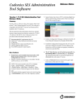
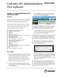


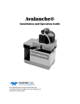

![Fio 2.0 UM ECU [ENG]](http://vs1.manualzilla.com/store/data/005638068_1-6dee15c8bb797972f1fa6aeeeee54189-150x150.png)