1
DVD Recorder
DVDR3380
DVDR3380/05/31/51/58
Service Instruction
CLASS 1
LASER PRODUCT
Contents
1
2
3
4
5
Technical Specifications and Connection Facilities
Test Disc & Repair Hints
Firmware Upgrading
Service Flow chart
Directions For Use
Page
2
5
6
8
13
The 2006 range DVD Recorder products are repaired centrally.
Defective sets must be identified, labelled and stored for pick-up.
This document gives full instructions for a functional check.
Technical information to repair faulty sets is therefore not provided in this document.
To test in-coming sets the following must be performed:
1. Verify / Reproduce the customer’s problem
2. Verify that set has latest Firmware (see chapter 3) and upgrade if it is not the latest version.
3. Full functional check
©Copyright 2006 Philips Consumer Electronics B.V. Eindhoven, The Netherlands.
All rights reserved. No part of this publication may be reproduced, stored in a
retrieval system or transmitted, in any form or by any means, electronic,
mechanical, photocopying, or otherwise without the prior permission of Philips.
Published by KC-TE 0617 AV Systems
Version 1.0
Printed in the Netherlands
Subject to modification
EN 3139 785 31810
EN 2
1.
3139 785 31810
Technical Specifications and Connection Facilities
1.
Technical Specifications and Connection Facilities
1.1
General:
Mains voltage
Mains frequency
Power consumption (record)
Standby Power Consumption
1.2
1.2.6
:
:
:
:
Automatic Search Tuning
Scanning time without RF signal
Stop level (vision carrier)
Maximum tuning error of a recalled
program
Maximum tuning error (drift) during
operation
220V – 240V
50 Hz
27 W
<3W
RF Tuner
Test equipment: Fluke 54200 TV Signal generator
Test streams: PAL BG Philips Standard test pattern
1.2.1
System
PAL B/G, PAL D/K, SECAM L/L’, PAL I
1.2.2
RF - Loop Through:
Frequency range
Gain: (ANT IN - ANT OUT)
w/o Amplifier
Gain: (ANT IN - ANT OUT)
with Amplifier
1.2.3
: 43 MHz – 860 MHz
: -4dB ± 2dB
: 2dB ± 3dB
Receiver:
PLL tuning with AFC for optimum reception
Frequency range
: 45.25 MHz – 857 MHz
Sensitivity at 40dB S/N
(video unweighted)
: ≤ 40dBμV at 75 Ω
(high end)
≤ 60dBμV at 75 Ω
(low end)
1.2.4
Video Performance:
Channel 25 / 503,25 MHz,
Test pattern: PAL BG PHILIPS standard test pattern,
RF Level 74dBV, Measured on SCART 1
Frequency response
: 0.1 MHz – 4 MHz ± 3dB
Group delay (0.1 MHz - 4.4 MHz)
: 0 nsec ± 150 nsec
1.2.5
Audio Performance:
Audio Performance Analogue - HiFi:
Frequency response at SCART 1
(L+R) output
: 100 Hz – 12 kHz / 0 ±
3dB
S/N Ratio (20Hz – 20kHz)
unweighted
: ≥ 40dB
Harmonic distortion (1 kHz, ± 25
kHz deviation)
: ≤ 1.5%
Audio Performance NICAM:
Frequency response at SCART 1
(L+R) output
S/N Ratio (20Hz – 20kHz)
unweighted
Harmonic distortion (1kHz, ± 25
kHz deviation)
: 40 Hz – 15 kHz / 0 ±
3dB
: ≥ 65dB
: ≤ 0.5%
Tuning
: 3min. typical
: ≥ 37dB/μV
: 62.5 kHz
: ± 100 kHz
Tuning Principle:
Automatic B, G, I, DK and L/L’ detection
Manual selection in “STORE” mode
1.3
Analog Inputs / Outputs
1.3.1
SCART 1 (Connected to TV)
Pin Signals:
1 Audio-out R
1.8V RMS
2 Audio-in R
3 Audio-out L
1.8V RMS
4 Audio GND
5 Blue / Chroma GND
6 Audio-in L
7 Blue-out
0.7Vpp ± 0.1V into 75Ω
8 Function switch
< 2V = TV
> 4.5V / < 7V = asp. Ratio 16:9 DVD
> 9.5V / < 12V = asp. Ratio 4:3 DVD
9 Green GND
10 P50 control
not use
11 Green out
0.7Vpp ± 0.1V into 75Ω
12 NC
13 Red / Chroma GND
14 Fast switch GND
15 Red-out /
0.7Vpp ± 0.1V into 75Ω
Chroma-out
300mVpp ± 3dB
16 Fast switch
RGB / CVBS
or Y out
< 0.4V into 75Ω = CVBS
>1V / < 3V into 75Ω = RGB
17 Y/CVBS-out GND
18 CVBS-in GND
19 CVBS-out / Y-out
1Vpp ± 0.1V into 75Ω
20 CVBS-in
21 Shield
Technical Specifications and Connection Facilities
1.3.2
1.3.3
SCART 2 (Connected to AUX)
1.4
Digital Inputs / Outputs
Pin Signals:
1 Audio-out R
1.8V RMS
2 Audio-in R
3 Audio-out L
1.8V RMS
4 Audio GND
5 Blue / Chroma GND
6 Audio-in L
7 Blue-in
8 Function switch
9 Green GND
10 P50 control
11 Green-in
12 NC
13 Red / Chroma GND
14 Fast switch GND
15 Red-in /
Chroma-in
16 Fast switch
RGB / CVBS or Y in
17 CVBS-out GND
18 Y / CVBS-in GND
19 CVBS-out
1Vpp ± 0.1V into 75Ω
20 CVBS-in / Y-in
21 Shield
1.4.1
Digital Output
Audio/Video Front Input Connectors
1.5.1
Audio - Cinch
Input voltage
Input impedance
: 2.2Vrms
: > 10kΩ
Video - Cinch
Input voltage
Input impedance
: 1Vpp ± 3dB
: 75Ω
Out 1
1.4.2
Audio - Cinch
Output voltage
Output impedance
1.3.5
Specification of consumer use digital VCR’s using 6.3mm
magnetic tape – dec.1994
Mechanical connection according to Annex of IEC 61883-1
1.5
Video - Cinch
Output voltage
Output impedance
: 1Vpp ± 3dB
: 75Ω
Video - YC (Hosiden)
According to IEC 933-5
Superimposed DC-level on pin 4 (load > 100kΩ)
< 2.4V is detected as 4:3 aspect ratio
> 3.5V is detected as 16:9 aspect ratio
Output voltage Y
: 1Vpp ± 3dB
Input impedance
: 75Ω
Output voltage C
: 300mVpp ± 3dB
Input impedance
: 75Ω
SCART (RGB)
SNR
Bandwidth
1.6
Audio Performance
1.6.1
Cinch Output Rear
Output voltage 2 channel mode
Channel unbalance (1kHz)
Crosstalk 1kHz
Crosstalk 16Hz-20kHz
Frequency response 20Hz-20kHz
Signal to noise ratio (unweighted)
Dynamic range 1kHz
Distortion and noise 1kHz
Distortion and noise 16Hz-20kHz
Intermodulation distortion
Mute
1.7
: ≥ 55dB on all output
: 4.8MHz -3dB
:
:
:
:
:
:
:
:
:
:
:
2Vrms ± 1dB
< 0.22dB
> 110dB
> 100dB
± 0.2dB
< -95dB
< -90dB
< 85dB
< 85dB
< -94dB
< -100dB
:
:
:
:
:
:
:
:
:
:
:
1.6Vrms ± 2dB
< 1dB
> 85dB
> 70dB
± 0.5dB
> 80dB
> 75dB
> 75dB
> 50dB
> 70dB
> 80dB
:
:
:
:
5.5mm
WxDxH:435x322x43mm
3kg
4kg
Scart Audio
Output voltage 2 channel mode
Channel unbalance (1kHz)
Crosstalk 1kHz
Crosstalk 16Hz-20kHz
Frequency response 20Hz-20kHz
Signal to noise ratio (unweighted)
Dynamic range 1kHz
Distortion and noise 1kHz
Distortion and noise 16Hz-20kHz
Intermodulation distortion
Mute
Out 2
: 2Vrms max.
: > 10kΩ
Video Performance
All outputs loaded with 75Ω
SNR measurements over full bandwidth without weighting.
: 2Vrms max.
: > 10kΩ
Audio - Cinch
Output voltage
Output impedance
Digital Video Input (IEEE 1394)
Implementation Standard according:
IEEE Std 1394-1995
IEC61883 - Part1
IEC61883 - Part 2 SD-DVCR (02-01-1997)
1.6.2
Component Video Cinch Y/Pb/Pr
according EIO-770-I-A, EIA-770-2
EN 3
Digital Audio – Coaxial / Optical
LCM
: according IEC 60958
MPEG 1, MPEG 2, AC3
: according IEC 61937
DTS
: according IEC 61937 +
addendum
Video - YC (Hosiden)
According to IEC 933-5
Superimposed DC-level on pin 4 (load > 100kΩ)
< 2.4V is detected as 4:3 aspect ratio
> 3.5V is detected as 16:9 aspect ratio
Input voltage Y
: 1Vpp ± 3dB
Input impedance Y
: 75Ω
Input voltage C
: 300mVpp ± 3dB
Input impedance C
: 75Ω
1.3.4
1.
3139 785 31810
Dimensions and Weight
Height of feet
Apparatus
Weight without packaging
Weight with packaging
EN 4
1.
3139 785 31810
1.8
Laser Output Power & Wavelength
1.8.1
DVD
: 0.8mW
: 20mW
: 650nm
Video Playback
1.
CD
Output power
Wavelength
1.9
1.10 Playability
DVDR3380
Output power during reading
Output power during writing
Wavelength
1.8.2
Technical Specifications and Connection Facilities
: 0.3mW
: 780nm
2.
Read / Write Speed
Type of Disc (Function)
Read Speed CD
Read Speed DVD
Disc Rotation Speed
7X CAV
4X CAV
Write Speed DVD+R/+RW
2.4X ZCAV
Write Speed DVD-R/-RW
2X
Disc Media:
CD-R/-RW, MP3CD, VCD/SVCD,
DVD-Video,
DVD+R/+RW,
DVD-R/-RW,
DVD+RL DL
Compression
Format:
MPEG1, MPEG2
DivX 3.11, DivX
4.x, DivX 5.x, DivX
6.0
x
x
Audio Playback
1.
2.
3.
Disc Media:
CD, CD-R/-RW,
MP3-CD
Compression
Format:
Dolby Digital, MP3,
MPEG2 Multichannel, AAC,
WMA
MP3 bit rates: 32256 kbps and VBR
x
x
x
Still Picture Playback
1.
2.
Disc Media:
Picture CD
Picture
Compression
Format:
JPG
x
x
Test Disc & Repair Hints
2.
Test Disc & Repair Hints
2.1
Test Disc
1)
2)
3)
4)
2.2
7104 099 96611
9965 000 25728
-
CD-RW printed Audio Disc
DVD Player Test Pack
Blank DVD+RW
Blank DVD-RW
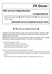
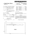
Open the DVD Tray manually
Note:
This procedure needs to be performed on
condition that:
- a customer’s Disc is jammed in the DVD Tray
- the DVD Tray cannot be open via the normal
open/close button on the set.
1) Place the set on the table with the bottom faced upwards
as shown below.
2) Insert a screw driver into the slot and open the DVD Tray
by sliding the screw driver in the direction shown.
1
2
Figure 2-1
3139 785 31810
2.
EN 5
EN 6
3.
3139 785 31810
3.
Firmware Upgrading
3.1
Firmware Upgrading
Firmware Upgrading
Important Instructions
• The Drive Upgrade and Loader Upgrade procedures has to be recorded into 2 separate disc.
A. Preparation to upgrade firmware:
1.
2.
3.
Unzip the zip-archive file
Copy the files into different folder for burning into separate CD-R/CDRW.
Start the CD Burning software and create a new CD project (data disc) with the following settings:
File system
: Joliet
Format
: MODE 2: CDROM XA
Recording mode : SINGLE SESSION (TRACK-AT-ONCE), FINALIZED CD
Note: Long file name is necessary for the preparation of the upgrade disc
4.
5.
Place the file into the root directory of the new CD project.
Burn the data onto CDRs or CD-RWs
B. Procedure to apply the Drive upgrade:
1.
2.
Open the tray and load the Upgrade CDROM with Drive Upgrade file.
The tray closes and set will display:
“DRV UPG”
3.
The OSD will display
“Loader Software Upgrade Disc detected.Select OK to start upgrading or CANCEL to exit.”
4.
5.
Click on the OK button.
The set will display:
“DRIVE UPGRADING”
With the OSD display
“Upgrading Software. Please Wait. Do not switch off the power.”
The whole process takes less than 5 minutes
Note: Do not press any buttons or interrupt the mains supply during the upgrading process, otherwise the set may becomes
defective.
6.
When the upgrade is completed the tray will open automatically and the set will display:
“Loader Upgrade process has completed successfully .Press <OK> to reboot system.”
7.
The tray open and the set will display:
“DRV OK”
8.
Press <OK> and the set goes to standby .
Firmware Upgrading
3139 785 31810
3.
EN 7
B. Procedure to apply the software upgrade:
1.
2.
Open the tray and load the Upgrade CDROM with Software upgrade file.
The tray closes and set will display:
“Upgrading SW”
3.
The OSD will display
“Software Upgrade Disc detected.Select OK to start upgrading or CANCEL to exit .”
4.
5.
Click on the OK button.
The set will display:
“Upgrading SW”
and the OSD will display
“Upgrading Software. Please Wait. Do not switch off the power.”
The whole process takes less than 5 minutes
Note: Do not press any buttons or interrupt the mains supply during the upgrading process, otherwise the set may becomes
defective.
6.
When the upgrade is completed the tray will open automatically and the set will display:
“System is successfully upgraded.Remove disc from tray and reset system.”
7.
The tray open and the set will display:
“SW DONE”
8.
and the tray will open automatically for user to remove CD-ROM.
Press <OK> and the set goes to standby .
C. How to read out the firmware version to confirm set has been upgraded:
1.
2.
3.
4.
5.
Power up the set.
Ensure no disc inside the loader,if no ,open the tray to remove the disc and close the tray.
Press <0> <0> <0> <9> in succession
Press <OK> button
The TV connected to the set will display:
“DVDR3380_EU_V03_07,Region:2, Drive 45.04.05.04
Build 0091 Mar 7 2006,12:17:31 Stroke:31 ”
EN 8
Service Flow Chart
3139 785 31810
4.
4.
Service Flow Chart
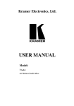
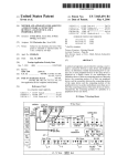
4.1
Start Process
Start
No
Is the
complaint
documented ?
Yes
Is it a known
complaint ?
Is it a
Hardware
problem ?
Yes
Yes
No
No
A
(Verification
Test)
No
Is Firmware
solution
available ?
Yes
Upgrade to latest
Firmware
Service W/S to contact the Trade /
Customer to work out a action plan.
Examples:
- explain them that the Firmware
solution is not ready
- Upgrade disc will be send
to them the moment solution
is ready
- etc.
Is the
complaint
solved ?
Yes
Return set to Customer with
Report on action done
No
- Attached a Defect Description Report
and Proof of Purchase.
- Pack defective set.
- Store defective set for pick-up.
Send refurbished set from pool
stock to Trade / customer
Service Flow Chart
4.2
3139 785 31810
4.
EN 9
Verification Process
A
(Verification
Test)
Connect up the Recorder
to TV antenna, TV set
and an External source
Can the set
Start-up ?
No
Yes
Check the Firmware
version on the set
Is Firmware the
last released
version ?
No
Upgrade to latest
Firmware
Yes
B
Recording
Check
C
D*
Playback
Check
System
Menu
* If complaint is related to
System Menu setting
Are the
checks result
ok ?
Yes
Return set to Customer with
Report on action done
No
- Attached a Defect Description Report
and Proof of Purchase.
- Pack defective set.
- Store defective set for pick-up.
Send refurbished set from pool
stock to Trade / customer
EN 10
4.3
3139 785 31810
4.
Service Flow Chart
Recording Process
B
Recording
Check
Test disc:
Blank DVD+RW
Make a short manual recording from the
following source:
- Tuner
- CAM 1 (Front CVBS)
- DV
- Ext 1
- Ext 2
1) Insert a recorded DVD+R/+RW disc
2) Press Top Menu button and check the
Disc editing features
Examples:
- Play
- Rename / Erase Disc
- Record New Title
- Overwrite / Lock Disc
Note: The displayed option in the disc
editing menu differ depending on the
situation & disc type
Does Disc
Editing
functions ?
Playback the recorded disc to check
No
No
Yes
Yes
1) Play a recorded DVD+R/+RW disc
2) Press Disc Menu button and check Title
editing features
Examples:
- Play / Rename Title
- Edit Title (same as press Edit button
during play)
- Erase / Append Title
- Overwrite Title / Disc
Note: The displayed option in the disc editing
menu differ depending on the situation & disc
type
Make a Timer recording with:
1) Manually
2) VPS/PDC on and off
3) Show View System
4) external Cable Box/Satellite
Receiver
Playback the recorded disc to check
No
Does Title
Editing
functions ?
Does manual
recording
functions ?
Are Timer edit &
delete feature
working ?
No
Yes
Yes
No
Continue
Does Timer
recording
functions ?
Yes
- Attached a Defect Description Report
and Proof of Purchase.
- Pack defective set.
- Store defective set for pick-up.
Send refurbished set from pool
stock to Trade / customer
Continue
Service Flow Chart
4.4
3139 785 31810
Playback Process
C
Playback
Check
Test disc:
DVD Player Test Pack (12NC: 9965 000 25728)
CD-RW Printed Audio disc (12NC: 7104 099 96611)
Playing the DVD video disc and check the
following:
- Pause & Search Fwd / Rev
functitons
- Next & Previous chapter
- Audio, Subtitle & Angle functions
- T/C options
No
Does the set
work ?
Yes
Playing other type of disc:
1) Use discs of DVD PLAYER TEST PACK for:
- (Super) Video CD
- MP3 disc
- Picture disc (slide show)
- special DVD playback check by layer change test using
DVD disc of this package
2) DivX 3.11, 4.x, 5.x, 6
3) For AUDIO CD use of CD-RW printed Audio Disc to check:
- Track 3 finger print
- Track 8: 600u black dot (max. after 1 min.)
No
- Attached a Defect Description Report
and Proof of Purchase.
- Pack defective set.
- Store defective set for pick-up.
Send refurbished set from pool
stock to Trade / customer
Does the set
work ?
Yes
Continue
4.
EN 11
EN 12
4.5
3139 785 31810
4.
Service Flow Chart
System Menu Process
D
System Menu Check
System Menu - General and check the following
features:
- Screen Saver
- Country
- Video Output Format
- Restore Factory settings
System Menu - Playback and check the
following features:
- TV Aspect Ratio
- Parental Rating Level
- Digital Audio Output
System Menu - Record and check the following
features:
- Auto Chapter Marker
- Default Recording Source
- Default Recording Mode
System Menu - Language and check the
following features:
- On Screen Display Language
- Default Disc Menu Language
- Default Subtitle Language
- Default Audio Language
System Menu - Channel Setup and check the
following features:
- Channel Search
- Modify Channel Information
- Sort Channels
System Menu - Clock and check the following
features:
- Date (dd/mm/yy)
- Time (hh:mm:ss)
- Date-Time Setting
- Show DivX Registration code
Does the
set work ?
No
Yes
Continue
- Attached a Defect Description Report
and Proof of Purchase.
- Pack defective set.
- Store defective set for pick-up.
Send refurbished set from pool
stock to Trade / customer
21191
Remote Control
and 2 batteries
RF Coaxial Cable
DVD Player/ Recorder
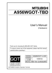
What’s in the box?
SCART Cable
User
Manual
Enjoy
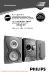
Set up
Connect
ANTENNA-IN
AUX - I/O
EXT 1
TO TV - I/O
SCART IN
~
MAINS
To AC
power
E Connect the power cable from the recorder to
an AC power outlet.
D Use the SCART cable to connect the EXT1 TO
TV-I/O socket on this recorder to the
corresponding SCART input socket on the TV.
C Use the supplied RF coaxial cable to connect the
TV-OUT
jack on this recorder to the
Antenna In jack on the TV.
B Connect the antenna cable to the ANTENNAIN
jack on the recorder.
A Before connecting, unplug the antenna cable that
is currently connected to your TV.
TV-OUT
EXT 2
Philips recorder
(rear)
To antenna or
set-top box
Television (rear)
ANTENNA-IN
EXT 2
AUX - I/O
EXT 1
TO TV - I/O
SCART IN
~
Philips
recorder
(rear)
MAINS
Television (rear)
For additional connection diagrams, see
the accompanying User Manual.
Note In this setup, the VCR cannot record TV
programmes.
C Connect the power cable from your VCR to an
AC power outlet.
B Use another SCART cable (not supplied) to
connect the EXT2 AUX-I/O SCART socket
on this recorder to the SCART OUT socket on
the VCR.
A Follow the steps under ‘Basic Connections’
before you proceed to step B below.
TV-OUT
To
AC power
VCR or similar
device (rear)
To antenna or
set-top box
B Connecting
Your new Philips recorder replaces the VCR for your
recording needs. First, unplug all the connections
from your VCR.
A Before Connecting
Connection with a VCR or
similar device
Start with the ‘Basic Connection.’
If you have a VCR, follow the instructions for ‘Connection with a VCR or similar device’.
Connect
Basic Connection
1
Set up
Philips record
C In case you do not see the record
wallpaper, press “0” and the Cha
button on the TV’s remote contr
(or AV, SELECT, ° button) until
screen. This is the correct viewin
the recorder.
Note If connected to your VCR, mak
is switched off or in standby mode bef
proceeding.
B Switch on the TV set.
A Press STANDBY-ON on the re
STANDBY-ON
A Finding the viewing cha
2
3139 785 31810
e Philips N.V.
.
.
ENU
ATE’
1
2
3
Quick Start Guide
DVDR3380
Directions For Use
REC
.
e stored
ct the
rnal
DVD Player/ Recorder
5.
Directions For Use
5.
EN 13
The following except of the Quick Use Guide serves as an introduction to the set.
The Complete Direction for the Use can be downloaded in different languages from the internet site of Philips Customer care Center:
www.p4c.philips.com
MAINS
s, see
V
R to an
) to
socket
cket on
ons’
Philips
recorder
(rear)
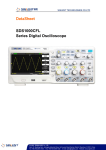
C In case you do not see the recorder’s blue
wallpaper, press “0” and the Channel Down
button on the TV’s remote control repeatedly
(or AV, SELECT, ° button) until you see this
screen. This is the correct viewing channel for
the recorder.
Note If connected to your VCR, make sure it
is switched off or in standby mode before
proceeding.
B Switch on the TV set.
Initial Installation
PAL
Video Output Format
Restore Factory Settings OK
Germany
On
Country
Screen Saver
System Menu - General
on the remote
.
and press right
.
and press right
.
to
to
F Press SYSTEM MENU
to exit.
Note The settings will be updated according to the
broadcast channel information of preset Programme
Number 1.
Use the numeric keypad 0
-9
input the date/time, then press OK
confirm.
Select { Date (dd/mm/yy) } or { Time
(hh/mm/ss) } and press OK .
���Highlight
E Setting the date and time.
Select { Channel Search } and press OK
on the remote control to start automatic TV
channel search.
���Highlight
D Setup and install TV channels.
Select { On-Screen Display Language } and
press right
to access the options. Press
OK
to confirm your selection.
and press right
� To record a TV programme, use up
���Highlight
Go to www.philips.com/support.
1
2
4
6
4.7 GB DVD±R/±RW disc
Hours of Recording that can be stored
repeatedly to select the
12 NC 3139 245 21191
www.philips.com
2006 © Koninklijke Philips N.V.
All rights reserved.
G To playback the recording, press DISC MENU
, select the title and press PLAY
.
F To end recording, press STOP
. ‘UPDATE’
will be displayed on the recorder.
E Press REC
to start recording, press REC
again to automatically record 30 minutes.
Types of discs for recording
High Quality HQ
Standard Play SP
Extended Play EP
Super Long Play SLP
Record Quality
C Press REC MODE
recording mode.
Recording from the TV or an external
device (continued)
Quic
Remote Control
and 2 batteries
What’s in the
Directions For Use
Online
See the user manual that came with your Philips recorder.
User Manual
Need help?
or
keys to scroll through the channels,
down
or press 0
-9
to select the channel that
you want to record.
A Insert a recordable DVD disc in the
tray.
C Select the OSD language.
or
B Press REC SOURCE
repeatedly to select
the source to record from. (eg, TUNER, CAM1,
DV, EXT1 or EXT2).
Recording from the TV or
an external device
Start Recording
D To stop playback, press STOP
.
B Press DISC MENU
and use up
keys to select a title.
down
C Press PLAY
to start playback.
A Press OPEN/CLOSE
on the front of
the recorder, load in a disc and close the disc
tray.
Start playback
B Select the country of your residence.
and press right
.
� Highlight
Select { Country } and press right
to
access the options. Press OK
to confirm
your selection.
Note Use up
or down
keys to toggle through
the options. Select an item by pressing right
. To
confirm a setting, press OK .
control.
A Press SYSTEM MENU
B
DVD Player/ Recorder
3139 785 31810
~
(rear)
Philips recorder (front panel)
A Press STANDBY-ON on the recorder.
STANDBY-ON
A Finding the viewing channel
3
Enjoy
5.
for your
tions
or
2
Set up
EN 14