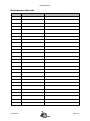
1
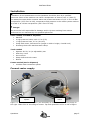
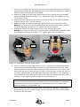
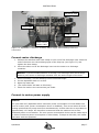
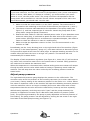
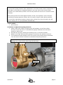
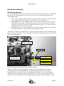
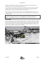
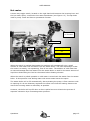
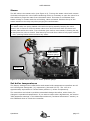
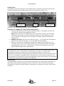
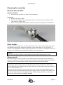
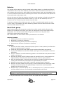
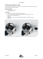
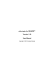
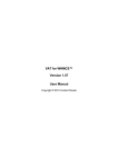
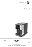
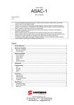
CONTENTS Installation and user manual Speedster Document ID: Sup-Sium-Eng Speedster Date of issue: August 21, 2013 Revision date: August 10, 2015 page 1 CONTENTS Parts identification ................................................................................................. 3 Unpack................................................................................................................. 4 Parts included in standard shipment......................................................................... 4 More information on the USB flash drive ................................................................... 4 Installation ........................................................................................................... 5 Connect water supply.......................................................................................... 5 Connect water discharge ..................................................................................... 7 Connect to mains power supply ............................................................................ 7 Adjust pump pressure ......................................................................................... 8 Using the machine ................................................................................................10 Brewing espresso ..............................................................................................10 Shot timer ........................................................................................................11 Hot water .........................................................................................................12 Steam ..............................................................................................................13 Set boiler temperatures ......................................................................................13 Cleaning the machine............................................................................................15 Remove filter basket ..........................................................................................15 Filter holder ......................................................................................................15 Steam wand .....................................................................................................15 Exterior ............................................................................................................16 Back flush group ...............................................................................................16 Replace group seal ............................................................................................17 Clean group dispersion plate ...............................................................................18 Maintenance ........................................................................................................19 Recommended maintenance scheme ....................................................................19 Maintenance Records .........................................................................................20 Contact information ..............................................................................................21 Speedster page 2 WELCOME Parts identification 12 11 10 9 8 7 13 6 5 14 15 16 17 18 1 2 3 4 Figure W 1. Showing the main operational parts of the Speedster 1. Mains switch 2. Coffee boiler PID with temperature display 3. Hot water spout 4. 3-way brewing lever 5. 3-way hot water toggle switch 6. Coffee boiler pressure gauge 7. Hot water valve 8. Hot water valve knob (no operational function) 9. Visible end of pre-infusion piston 10. Group head 11. Shot timer display 12. Steam valve knob 13. Steam valve 14. Steam boiler pressure gauge 15. Steam tip 16. Drip tray 17. Steam boiler thermostat with temperature display 18. Filter holder Speedster page 3 INSTALLATION Unpack Tools needed Phillips screw driver no. 2 Procedure 1. Remove the lid of the crate. 2. Remove the side panels. 3. Lift the machine by its legs. Warnings! The valves at both sides of the group are not designed to lift the machine. Lifting the machine by these may cause the frame to bend which results in unrepairable damage. Although sturdy, the brew lever might bend when lateral force is applied. A bent brew lever may lead to malfunction of the lever. Parts included in standard shipment Accessories Stainless steel filter holder, 2-cup spout Stainless steel filter holder, 1-cup spout Water pump with electric motor Two high-pressure water supply hoses, each 1.5 m (5 ft) One high pressure water supply hose, 0.5 m (20 in) Discharge hose, inner diameter 16 mm (0.64 in) Stainless steel hose clamp for discharge hose KVDW Stainless steel tamper Blind filter Jar with cleaning powder Group brush Group screen extractor Drain hose Speedster T-shirt 2 KVDW shot glasses USB flash drive with comprehensive user and maintenance manual Spare parts there is a Barista Kit included with the machine to facilitate routine maintenance More information on the USB flash drive Included in the shipment is a USB flash drive with comprehensive information on the Speedster espresso machine. Besides this installation and user manual, it includes an explanation of how the machine works, some notes on (tap) water quality and detailed descriptions of materials needed and procedures to follow whilst performing maintenance routines. Speedster page 4 INSTALLATION Installation Caution! Installation of and maintenance on the Speedster should be done by a qualified technician. Parts of the machine can reach a temperature of close to 140 °C (284 °F). The steam/hot water boiler contains water and pressurised steam of 135 °C at 1.45 Bar overpressure (275 °F at 21 PSI), temperature and pressure in the coffee system reaches up to 96 °C at 12 Bar overpressure (205 °F at 175 PSI). Danger We cannot be held responsible for damage and/or injuries resulting from actions performed on our machines by non-qualified personnel. Parts needed, included in shipment Machine 2 high pressure hoses, each 1.5 m (5 ft) 1 high pressure hose, 0.5 m (20 inch) Pump with motor, 29x14x19 cm (length x width x height; 12x6x8 inch) Discharge hose with stainless steel clamp Tools needed Spanner 20-22, 30 (or adjustable) mm Allen key 4 mm Screw driver Sharp knife and side cutter Bucket Extras needed (not in shipment) suitable water treatment system Connect water supply water treatment system pump with motor Figure I 1. Water treatment system (not included) on left is connected to the pump on the right. Water flow is according to arrows. Tap and Speedster will be to left of figure. Speedster page 5 INSTALLATION 1. Use a 20 mm spanner to attach one end of a long high pressure hose to the tap. A gasket is not needed, the ball-shaped brass end will seal upon tightening. Inside thread on high pressure hose is 3/8”BSPS. 2. Attach the other end of the high pressure hose to the ingoing side on a suitable water treatment system (see Figure I 1). Tighten with a 20 mm spanner. Do not use excessive force. 3. Attach the short high pressure hose to the outgoing side on the water treatment system. Tighten with a 20 mm spanner. 4. Attach the other end of the short high pressure hose to the inlet of the pump. Beware! The inlet of the pump is marked with an arrow pointing down, towards the pump-housing (see Figure I 2). Tighten with 20 mm spanner. 5. Attach the second long high pressure hose to the outlet of the pump. Beware! The outlet of the pump is marked with an arrow pointing upwards, away from the pump-housing (see Figure I 2). Tighten with a 20 mm spanner. outlet outlet inlet inlet Figure I 2. Pump with inlet and outlet shown. 6. Hold the loose end of the high pressure hose in a bucket and open the tap slowly. Flush the water treatment system according to manufacturer's instruction. Then flush the pump for a minute (the pump-motor does not have to run). Check if the water does not show a strange colour or smell. Close the tap, connect the hose to the fitting at the bottom of the Speedster with a 20 mm spanner. The Speedster may be tilted in such a way that it rests on the two hind-legs and the back of the machine, or use (wooden) blocks under the feet see Figure I 3. Note! Use a permanent marker to write the expiry date on the cartridge and replace the cartridge as advised by the manufacturer but at least every 12 months, even when the capacity is not exceeded yet. 7. Open the tap and check the earlier made connections for leakage. Tighten when needed but do not use excessive force. In the meantime, the front (coffee) boiler will start to fill with water. Speedster page 6 INSTALLATION discharge pipe pump cable water supply power mains supply cable discharge hose Figure I 3. Speedster is tilted on its back, water supply and discharge hose are connected. Connect water discharge 1. Position the stainless steel hose clamp on one end of the discharge hose. Slide the end of the hose over the discharge-pipe of the drip tray (see Figure I 3) and tighten the hose clamp. 2. Insert the other end of the discharge hose into the sewer or a discharge container. Beware! To prevent sedimentation of smudge, the discharge hose should slope down to your sewer or discharge container over the entire length of the hose. 3. 4. 5. 6. 7. When necessary, cut the discharge hose to desired length. Put the Speedster back on its feet. Open the water tap. (The coffee boiler will start to fill slowly). Check for leaks in the connections just made. Connect to mains power supply Beware! The (220-240 VAC) Speedster has a maximum power consumption of 3100 Watts from your AC-outlet (max. power consumption device is disabled). This occurs when all three heating spirals and the pump are active simultaneously. At 230 Volts this is equivalent to approximately 13.5 amps. We therefore recommend that the machine has its own dedicated power circuit breaker. The max. power consumption device can be made active to reduce maximum power consumption to 2300 Watts, 10 amps at 230 VAC; see leaflet that came with the Speedster. Speedster page 7 INSTALLATION 110-120 VAC Speedster (see model tag) If you have ordered a 110-120 VAC version of the Speedster (max. power consumption device is active; 2050 Watts, 17.8 amps at 115VAC), you must connect your power mains to a 110-120 VAC power outlet. The pump is fed from the Speedster and the pump-motor will be marked 110-120 VAC as well. Where we speak of 230 VAC in the rest of this manual, you should read 110-120 VAC. 1. Make sure that the mains switch is in the "OFF"-position. The mains switch is mounted on the model tag on the front of the machine (see Figure W 1, item 1). 2. The thinner electrical cable attached to the Speedster is the pump cable (see Figure I 3) and has a special type of connector. Attach the pump cable to the pump motor using the special connectors. 3. Attach the other cable to a 230 VAC earthed power outlet. If your Speedster came without a mains plug, it is advised to attach the blue wire to the neutral in your power outlet. (Although there is no difference in operational aspect, this makes it easier to check the electrics in case of a malfunction.) 4. Make sure that the Speedster rests on its feet. Turn the mains switch on the machine to “ON”. Immediately put the 3-way brewing lever on the right hand side of the machine (Figure W 1, item 4) in the lowest position (“pump on”) until water without air leaves the group. This procedure expels all air from the coffee boiler. A separate bleeding procedure is not needed. After this leave the lever in its high “off” position. The machine will now automatically fill its steam boiler. The display of both temperature regulators (see Figure W 1, items 2 & 17) will not show any value until a minimum water level in the steam boiler is reached. Filling procedure will continue till it reaches the maximum level. When the temperature in the steam boiler reaches boiling point some steam will escape through the anti-vacuum valve which makes a hissing or sputtering sound inside the machine. This will stop when the valve is shut by the increasing pressure inside the steam boiler. Adjust pump pressure The right hand side pressure gauge displays the pressure in the coffee boiler. The minimum value is the line pressure of the incoming tap water (as in other water taps in your house). Factory setting of the maximum pressure in the boiler is 11-13 Bar. Above this value an expansion valve on the machine will open thus bleeding excessive pressure until the maximum value is no longer exceeded (this occurs when water with a lower temperature than the set value enters the coffee boiler, heats up and thus expands). While brewing espresso, with the group valve “open” and the pump activated, the pressure is supposed to increase up to 9 Bar when back pressure is present (coffee puck). The pressure generated by the pump is partly dependent on the line pressure of the building. The pump pressure can be adjusted by turning the set screw on the right hand side of the brass pump housing (see Figure I 4). Speedster page 8 INSTALLATION Notes Do not set the pump pressure with a blind filter in the filter holder. When a blind filter is used water in the system is trapped between a one-way valve and the blind filter. Therefore, the coffee boiler pressure will not drop when the set screw is turned counterclockwise. When pump pressure exceeds approximately 12 Bar, the expansion valve will open. Increasing the pump pressure further will not result in higher coffee boiler pressure. Do not set the operational pressure higher than 9,5 Bar since this will reduce the lifespan of valves, etc. in your Speedster dramatically. Tools needed Screw driver Procedure to adjust the pump pressure: 1. Place a filter with coffee of proper grind and quantity in the filter holder. As soon as the brew lever is activated the gauge indicates true extraction pressure, rather than 2. Activate the group by slotting the brewing lever in its lower position. 3. Observe the right hand pressure gauge to check how the pressure evolves. 4. To increase the pump pressure turn the screw in the pump housing clockwise. Turn the screw counter-clockwise to decrease the pump pressure. Beware! The set screw is made from brass and is easily deformed. To avoid damage use a screw driver that snugly fits the slot. set screw Figure I 4. Showing the set screw on the pump to change pump pressure. Speedster page 9 USER MANUAL Using the machine Brewing espresso The 3-way brewing lever on the right hand side of the machine (see Figure U 1) operates the group valve and the pump. The lever can be fixed in 2 slots and thus has three operating positions: 1. OFF. Lever in upper (resting) position. Group is inactive (valve is closed and pump is off). Water cannot flow from the coffee boiler to the coffee bed. 2. PRE-INFUSION. Lever in middle position. Group valve is open but pump is off. In this position (hot) water under line pressure can reach the coffee grounds which will wet and swell. This process is called manual pre-infusion. You may adjust the timespan of pre-infusion to your liking. 3. PUMP ACTIVE. Lever in lower position. Group valve is open and pump is activated. The water pressure on the coffee bed will increase to 9 Bar. Switching off is easily accomplished by a short down-right tap on the left hand ball on the lever. The lever will return to its resting position and the remaining pressure in the coffee filter will be discharged. progressive preinfusion cylinder brew lever coffee boiler pressure gauge off pre-infusion pump active Figure U 1. Brewing espresso: brew lever, lever positions, brew pressure (coffee boiler pressure) gauge and progressive pre-infusion cylinder. When you switch from resting position directly to the lower position, the primary increasing pressure is still absorbed by a piston and spring within the so-called “progressive pre-infusion cylinder” up to approximately 3 Bar. As soon as the piston reaches its ultimate position, the full pump pressure of 9 Bar is slowly applied to the coffee bed. You can easily check the functioning of the progressive pre-infusion as the Speedster page 10 USER MANUAL guiding rod of the piston will protrude through an opening in the front panel of the machine just left of the hot water tap (see Figure U 1). The extraction can be further manipulated by switching the lever from lower to middle position near the end of the extraction phase. Water pressure will then decrease to approximately 3 Bar (line pressure) but remains at that level. The progressive pre-infusion cylinder has the extra advantage that clean water in the cylinder is pushed through the group valve into the discharge after each extraction, thus rinsing the valve. Note Filling of the steam/hot water boiler is disengaged during brewing (brewing lever in middle or lower position) in order to prevent differences in extraction pressure. Shot timer when the group valve is active (open) for longer than 0.1 second, a timer first re-sets to zero and then starts to count. The display (see Figure U 2) will show the seconds passed since the valve was opened. It does not distinct between pump active or inactive. The shot timer may help you to determine the optimum grinder setting and coffee grounds dose to reach a perfect espresso (25-30 seconds). Figure U 2. The shot timer display. Speedster page 11 USER MANUAL Hot water A three-way toggle switch, located on the right hand side between the brewing lever and the hot water spout, controls the hot-water distribution (see Figure U 3). The tap knob itself is purely visual and has no operational function. tap knob; no function toggle switch spout very hot (>100°C) off hot (85-95°C) Figure U 3. Hot water: toggle switch, tap knob and hot water spout. When the switch is pushed downwards the machine will automatically mix a small amount of cold water with hot water from the steam boiler. The main advantage is that the result is a steady, non-sputtering, flow of hot water. The addition of cold water has as extra advantage that less water from the steam boiler is used for the same amount of liquid thus diminishing the load on the steam boilers heating element. When the switch is pulled upwards no cold water is mixed with hot water from the steam boiler. In this position near-boiling water with some steam leaves the spout. The steam boiler will re-fill automatically, also activating the pump. A flow restrictor with an opening of 0.6 mm diameter regulates the inflow such that the heating element can warm the incoming water as efficiently as possible. However, the boiler will not fill when a shot is pulled as not to disturb the process of espresso extraction by a fluctuating water pressure. Speedster page 12 USER MANUAL Steam The left valve is the steam valve (see Figure U 4). Turning the steam valve knob counterclockwise will open the valve. Before steaming milk it is necessary to open the valve for a short while to purge the water from the steam wand. This water is condensate from steam coming in contact with the cold tubing, valve and wand. Position the tip of the steam wand over the drip tray when purging the condensation. Warning! The steam valve is a spring loaded valve with the spring actually keeping the valve closed. Use no force to close the steam valve since this will wear down the Viton and silicone parts within the valve. Turn clockwise just until no more steam is leaving the tip, at that point the valve is closed. Total travel of the knob from close to fully open is about ¼ turn, opening further does not have any effect. steam boiler pressure gauge steam tip Figure U 4. Steam valve and tip and steam pressure gauge. Set boiler temperatures The factory settings of the coffee boiler and steam boiler temperature controllers are 93 and 135 degrees Centigrade (°C) respectively (200 and 275 °F). The 135 °C is approximately equivalent to 2.4 Bar steam pressure (1.4 Bar overpressure). The controllers are locked to prohibit unintended changes but allow, within limits, for changes in operational temperature. If you want to make other adjustments, see section “PID-parameter settings” in the Maintenance Manual (“technical information” section) on the USB flash drive to unlock the controller. Speedster page 13 USER MANUAL Coffee boiler The display of the PID-regulator of the coffee boiler is located on the front panel of the machine in between the on/off switch and the model tag (see Figure U 5). steam boiler controller on/off switch coffee boiler controller Figure U 5. Showing both controllers and on/off switch. Procedure to change the coffee boiler temperature 1. Press the SET/ECO key on the PID and keep pressed. The display will show the currently set operational temperature value. Note! When you press the SET/ECO key for 6 seconds or longer, the controller changes to ECO-mode (a lower temperature setting) and the display will read "Eco". Pressing the key again for 6 seconds will change it back to operational temperature. 2. Within 6 seconds, press the key with arrow up () to increase the temperature, press the key with arrow down () to decrease the temperature. 3. When you have set the temperature as desired release the SET/ECO key; the controller will return to its normal operation and will bring the boiler to its newly set temperature (mind you, cooling down to a lower set temperature will take longer than heating up the coffee boiler). Note! The temperature of the coffee water is measured by a probe in the coffee boiler. The temperature reading on the PID is thus the temperature within the boiler. The temperature of the water leaving the group at the group screen on top of the coffee bed will be 1.5-2.5 degrees Centigrade lower, depending on environmental conditions. You may account for this when fine-tuning the temperature setting on the PID. The procedure is described in the technical manual on the USB-stick. Steam boiler The steam boiler controller is in fact a device identical to the coffee boiler controller, but with different parameter settings such that it functions as a very precise thermostat. Changing the operational (steam boiler) temperature is the same as for the coffee boiler controller. Speedster page 14 USER MANUAL Cleaning the machine Remove filter basket Materials needed 1. Group screen extractor (or back end of teaspoon) Procedure 1. Remove the filter holder. 2. Pry the filter basket with the pointed end of the extractor from the filter holder (see Figure U 6Figure U 6). 3. When remounting the filter basket, make sure the spring snaps into the basket. Figure U 6. Pry filter basket from filter holder with the group screen extractor. Filter holder Remove the filter basket from the filter holder and clean it with a little washing up liquid and plastic scouring pad. Place the metal part of the filter holder for 10 minutes in a solution of 1 tablespoon of coffee dissolving powder in hot water. The bakelite handle will corrode in this solution and should thus be kept out of the solution. Beware! Never clean the filter holder in a dish washer as dish washer detergent will ruin it. Steam wand Milk easily sticks to the hot surface of the steam wand and tip and will leave baked on remains. Therefore, the steam wand and tip should be cleaned with a damp cloth directly after each use. Do not use this cloth for anything else than the steam wand. Beware! Immediately after steaming milk you should flush the steam wand with a little steam. This will prohibit milk creeping into the pipe, and even into the valve house, by means of the so called capillary rise. Flushing also prevents the 4 holes in the tip to clog. In the event that clogging occurs, place the end of the steam wand and tip for several minutes in a glass of hot water. The remains will soften and can be wiped off easily. NEVER scrape, grind or cut the steam wand or tip since it leads to avoidable damage. Speedster page 15 USER MANUAL Exterior The outside of the machine can be cleaned with window cleaner in a hand spray flask in combination with a soft, often washed, cotton cloth. When the machine is turned “on” it will be warm and you have to work swiftly to prevent stripes: spray and immediately rub. To remove difficult stains without scratching the surface of the aluminium side panels use silver polish and a soft cotton cloth. Lift the drip tray grill from the machine and clean it with washing up liquid and a sponge. Activate the group (without filter holder locked in) or let the hot water tap run for a moment and use a brush to push remains into the drain. To prevent clogging of the drain hose pour, as often as needed (with regular use once every 2 days), one teaspoon of coffee dissolving powder into the drain and flush it with some hot water down the drain. Back flush group Back flushing cleans the group and conduits from coffee residue which influences the taste of the extraction since fresh (hot) water is transported to the coffee bed through these parts. It is advised to back flush the group at least once a day and when intensively used several times per day. NB: a blind filter is a filter basket without perforations in the bottom. Materials needed Plastic group brush (included in shipment) Blind filter (included in shipment) Coffee dissolving powder (included in shipment) Group screen extractor (included in shipment) Procedure 1. Remove the filter holder, activate the pump (lever in lower position) and flush the group for approximately 5 seconds. 2. Clean the group screen and rubber group seal with the plastic group brush. 3. Pry the filter basket from the filter holder (see Figure U 6) and replace it with the blind filter. 4. Scoop 1 teaspoon of coffee dissolving powder in the blind filter and place the filter holder in the group. 5. Activate the pump until full 9 Bar pressure is reached (lever in lower position for approximately 5 seconds) and shut off the pump (lever in upper position). 6. Wait for approximately 3 seconds (the pre-infusion cylinder should have time to empty) then activate the pump again for approximately 5 seconds. 7. Repeat the last step 9 times (wait 3 seconds, activate pump 5 seconds). 8. Remove the filter holder from the group, clean the blind filter by flushing it under the tap, activate the pump for approximately 5 seconds to remove possible powder from the group screen. 9. Repeat step 6 (3 seconds pump “off”, 5 seconds pump “on”) 4 times but remove the filter holder and pour out remaining liquids between each flush. Note! Removing the filter holder is essential to prevent remnants of cleaning powder to settle between the plunger and housing of the 3-way group valve. 10. Pry the blind filter from the filter holder and replace the filter basket. Speedster page 16 USER MANUAL Replace group seal The group seal is made out of Viton and will harden in time. We advise to replace the group seal at least every 6 months or more often when needed. Materials needed Group screen extractor (or back end of a fork or spoon) Replacement group seal Procedure 1. Pry the group screen gently from the group using the group screen extractor as lever under bayonet-ring and in the ridge on the side of the group screen (see Figure U 7a). Pry left and right for even distribution of force. The screen will fall out together with the rubber group seal. Be sure to place the extractor in the ridge of the screen only. 2. Remove the group seal from the group screen. 3. One side of the group seal has a somewhat more rounded surface. When replacing the rubber group seal, make sure the rounded side of the ring is inserted into the group (facing upwards). Push the group seal not all the way to the end of the group screen (see Figure U 7b). Figure U 7a (left). Gently pry left and right with group screen extractor to remove group screen and group seal. Figure U 7b (right). Mount group screen with empty filter holder and group ring not pushed all the way on the group screen. 4. Remove the filter basket from the filter holder. Place group screen with group seal on the filter holder and insert into group, pushing upwards. Turn filter holder in bayonet, then remove filter holder. 5. Insert the filter basket to the filter holder. Turn into the group to finish pressing the group seal into the group. Speedster page 17 USER MANUAL Clean group dispersion plate The group dispersion plate ensures more uniform wetting of the coffee bed. When dirty, the wetting will become less uniform. Materials needed Group screen extractor Screw driver no.2 procedure 1. Remove group screen together with group seal. 2. Turn out 2 screws holding black POM dispersion plate (see Figure U 8). 3. Pull down black dispersion plate. 4. Clean all. Beware! Do not scrub the POM dispersion plate as it will scratch easily. 5. Re-install. Figure U 8. Shows dispersion plate mounted with 2 screws (left) and dispersion plate removed from group (right). Photos taken from bare coffee-boiler laying on its back. Speedster page 18 USER MANUAL Maintenance Below is the recommended maintenance scheme followed by a description of how the individual maintenance items should be carried out. Up to one year, the maintenance is easy and does not require any technical knowledge. However, checking, adjusting and/or replacing parts inside the machine should be done with care and requires some technical skills. Recommended maintenance scheme Daily (depending on use, see user manual) Clean filter holder Clean steam wand Backflush group Weekly (see user manual) Clean group dispersion plate Clean group screen Clean filter holder Every 3 months (see user and/or maintenance manual) Check water treatment system (or re-generate water softener) Grease steam wand ball and check play between nut and ball of steam wand; replace nut if necessary Check pump pressure Check and replace if necessary: group seal group screen filter basket filter holder clip Every 6 months (see maintenance manual) Replace group seal Check anti-vacuum valve for leakage Check safety-valve on hot water/steam boiler for leakage Check operation of expansion valve on heat-exchanger system Check O-ring and spring in progressive pre-infusion cylinder, grease O-ring and piston shaft Every 12 months (see maintenance manual) Replace: water treatment system filter cartridge (or more often) group screen filter basket filter holder clip Replace anti-vacuum valve Rebuild steam valve Clean probes, level and safety Every 5 years (see maintenance manual) Replace all solenoid valves Speedster page 19 USER MANUAL Maintenance Records Date Speedster Task Comments page 20 INFORMATION More information on the USB flash drive Included in the shipment is a USB flash drive with comprehensive information on the Speedster espresso machine. Besides this installation and user manual, it includes an explanation of how the machine works, some notes on (tap) water quality, detailed descriptions of materials needed and procedures to follow whilst performing maintenance routines, electrical schemes and a troubleshooting guide. Contact information Kees van der Westen ~ Espressonistic Works B.V. Van Elderenlaan 6 5581WJ WAALRE The Netherlands Telephone Email Website +31 40 2223433 [email protected] www.keesvanderwesten.com Ordering replacement parts [email protected] Speedster page 21