1
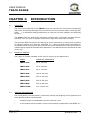
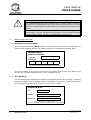
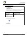
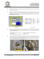
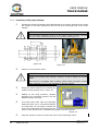
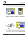
USER MANUAL
BUTT FUSION MACHINES
TRACK RANGE
(models from 160 to 1200)
Revision No. 1 - June 2008
Publication: MU-78-09E
NOTE !
The modifications made with respect to the revision immediately prior
to this edition are indicated by using 2 in the right hand margin.
USER MANUAL
TRACK RANGE
CONTENTS:
Page:
CHAPTER 1:
INTRODUCTION........................................................
1.1
Overview ......................................................
1.2
Range of models...........................................
1.3
General information........................................
1.4
Identification of unit .......................................
1.4.1 Marking of serial No...............................
1.4.2 “EC” marking .......................................
1.5
Safety measures against accidents ...................
1.6
“EC” declaration of conformity..........................
1.7
Guarantee .....................................................
5
5
5
5
6
6
6
7
8
9
CHAPTER 2:
DESCRIPTION OF UNIT..............................................
2.1
General information ........................................
2.2
Electro-hydraulic station .................................
2.2.1 Introduction.........................................
2.2.2 Parts of the hydraulic station..................
2.2.3 Using the hydraulic system ...................
2.3
Connections...................................................
2.3.1 Electric connections .............................
2.3.2 Hydraulic connections...........................
10
10
12
12
12
13
14
14
14
CHAPTER 3:
MODE OF USE............... ...........................................
3.1
Preparing the unit ..........................................
3.1.1 Connecting machine to a power source ....
3.1.2 Verifying temperature of heating plate.....
3.1.3 Hydraulic connections ...........................
3.1.4 Type of hydraulic station........................
3.2
Butt fusion procedure .....................................
3.2.1 General criteria for joining......................
3.2.2 Preparing the pipes and machine ...........
3.2.3 Trimming pipes/fittings..........................
3.2.4 Heating plate........................................
3.2.5 Butt fusion procedure ...........................
15
15
15
15
16
16
17
17
17
20
21
21
CHAPTER 4:
MAINTENANCE .........................................................
4.1
General information.........................................
4.1.1 Introduction.........................................
4.1.2 Storage ...............................................
4.1.3 Services...............................................
4.2
Maintenance of base framework .......................
4.2.1 Hydraulic cylinders, pressure hoses.........
4.2.2 Pipe adaptors........................................
4.2.3 General cleaning and greasing ...............
24
24
24
24
24
25
25
25
25
Edition: June 2008
Revision: No. 1
GENERAL INDEX -
3
USER MANUAL
TRACK RANGE
Page:
4.3
4.4.
4.5
CHAPTER 5:
4
Maintenance of heating plate ..........................
Maintenance of trimmer ................................
4.4.1 Trimmer face discs ..............................
4.4.2 Electric motor .....................................
Maintenance of hydraulic station......................
4.5.1 Introduction........................................
5.5.2 Maintenance........................................
TECHNICAL CHARACTERISTICS..................................
5.1
Base framework .............................................
5.2
Heating plate ................................................
5.3
Trimmer........................................................
5.4
Heating plate and trimmer holder.....................
5.5
Hydraulic station ............................................
5.6
Complete machine...........................................
5.7
Generator specifications...................................
5.8
Documentation...............................................
- GENERAL INDEX
25
25
25
26
26
26
26
27
27
27
27
27
28
28
28
28
Edition: June 2008
Revision: No. 1
USER MANUAL
TRACK RANGE
CHAPTER 1:
1.1
INTRODUCTION
OVERVIEW
The butt fusion machines of the TRACK range are used for the butt fusion of polythene
(PE) tubes and fittings although they can also be used to join other plastic resins (PP, PB,
PVDF, ...), in diameters ranging between 50 to 1200 mm (consult models in the following
section).
The Track range are butt fusion machines equipped with a manually operated electrohydraulic unit. They are of simple construction, ergonomic and easy to handle.
The technical data provided in this Manual is purely informative in nature and is subject
to changes without prior warning. ACUSTER, S.L., does not make itself responsible for
complaints made deriving from the incorrect use of this publication or of the errors and/or
omissions that might be detected after publication. This Manual should considered as part
of the unit.
1.2
RANGE OF MODELS
The range of models available at the time of writing up this Manual are:
1.3
MODEL
RANGE OF DIAMETERS
TRACK 160
50 to 160 mm
TRACK 250
75 to 250 mm
TRACK 315
90 to 315 mm
TRACK 400
160 to 400 mm
TRACK 500
250 to 500 mm
TRACK 630
355 to 630 mm
TRACK 800
630 to 800 mm
TRACK 1200
710 a 1200 mm
GENERAL INFORMATION
The development, documentation, production, testing and shipping of the products here
described have been manufactured:
C
complying with the applicable security measures, and
C
in accordance with the quality control requirements guaranteed by ACUSTER, S.L.
Edition: June 2008
Revision: No. 1
INTRODUCTION
- 5
USER MANUAL
TRACK RANGE
WARNING !
Only qualified personnel is authorized to carry out tasks either of fusion or
of reparation. This qualified personnel must be familiar with all the security
measures, potential dangers and maintenance regulations described in this
Manual.
The safe use of the products described require the appropriate
transportation, storing, installation and utilisation, and the careful handling
and monitoring of their periodic pre-established maintenance.
1.4
IDENTIFYING THE UNIT
1.4.1 Marking the Serial Number:
All the components of the TRACK range of machines: base framework, heating plate, the
trimmer and hydraulic station are marked with their corresponding identity plate.
ACUSTER S.L.
QUALITY CONTROL
UNIT Nº
" SERVICES
"
Juan de la Cierva, 1 - Políg. Ind. nº 1
Tel.(34)93 4703070 - Sant Just Desvern (Barcelona)
Figure 1
The serial number of the unit is included on the quality control plate. The dates of the
services are recorded subsequently in the 5 available boxes.
1.4.2 “EC” Marking:
The machines come provided with the plate corresponding to the “EC” marking, complying
with the European Union regulations of the new Machinery Directive (Directive 98/37/EC
of the European Parliament and Council, of 22nd June, 1998)
ACUSTER S.L.
EC
" MODEL:
"
SERIAL Nº
Juan de la Cierva, 1 - Políg. Ind. nº 1
Tel.(34) 93 4703070 - Sant Just Desvern (Barcelona)- SPAIN
Figure 2
6
- INTRODUCTION
Edition: June 2008
Revision: No. 1
USER MANUAL
TRACK RANGE
1.5
PROTECTION MEASURES AGAINST ACCIDENTS
Apply the following safety measures:
M
Keep the machine beyond the reach of non-authorised personnel, unqualified
personnel and children. Protect it from water, rain, snow, etc..
M
While moving the machine and during loading and unloading operations, take the
necessary safety measures to ensure that all the components of the machine
remain perfectly well tied down in the vehicle and that they do not receive knocks
during transportation.
M
Protect the connecting electrical cables of the trimmer, heating plate and that of
the connection to the mains, as well as the hydraulic pressure hoses from sharp
cutting objects.
M
Damaged electric cables and hydraulic pressure hoses should be replaced
immediately by the Technical Assistance Service of ACUSTER, S.L.
M
Always connect the unit to power points which have a trip switch and differential.
M
The machines which are not in use should be kept out of reach of non-authorised
personnel. They should be stored in a dry place with restricted access.
M
Always use appropriate work clothing.
For outdoor work, rubber gloves and boots with insulating soles are recommended.
In humid regions, these recommendations are essential.
For indoor fusion tasks, one should make sure there is sufficient ventilation in the
workspace.
M
Before using the machine each time, its external state must be checked as well as
its operating state. All the components must be correctly assembled to guarantee
it will function correctly.
M
Damaged components must be repaired or substituted by the Technical Assistance
Service of ACUSTER, S.L.
M
In the case the machine malfunctions, it must be sent to the Technical Assistance
Service of ACUSTER, S.L. immediately.
Edition: June 2008
Revision: No. 1
INTRODUCTION
- 7
USER MANUAL
TRACK RANGE
1.6
“EC” DECLARATION OF CONFORMITY
ACUSTER, S.L.
Juan de la Cierva, 1
Polígono Industrial Nº 1
08960 Sant Just Desvern
we declare under our sole responsibility that the butt fusion m achines of
the TRACK range, are m anufactured in agreem ent with the requirem ents
of the following Directives based on the following specifications:
Directive
Related Standards
98/37/EC
Safety of m achines
EN 1050; EN ISO 12100
EN 61310; EN 954; EN 982
EN 60204-1
2006/95/EEC
Low voltage
EN 60519-1
2004/108/EEC
Electrom agnetic com patibility
EN 6100-6-2
Sant Just Desvern, 8 th January 2008
Jaum e Puig
General Manager
E d ition : Ju n e 20 0 8
8
-
INTRODUCTION
R e vision : N o. 1
USER MANUAL
TRACK RANGE
1.7
GUARANTEE
Statement of guarantee:
All the butt fusion machines of the TRACK range are manufactured with high
quality materials and have been subjected to demanding tests of resistance and
operation, passing all the quality controls required in compliance with the
applicable regulations (see “EC” Declaration of Conformity).
Whatever the case and in the face of any eventuality that might arise during
the period of guarantee, we recommend that the following general conditions
of guarantee be read carefully.
General conditions of guarantee:
1.
ACUSTER, S.L. guarantees that this product does not have any
manufacturing defects at the time of purchase and extends this
GUARANTEE for a period of TWO YEARS.
2.
If during this period, the product sustains any kind of defect due to the
materials or its assembly, it will be possible to repair it without any
extra charge, whether for materials or labour, in the Technical
Assistance Service of ACUSTER, S.L..
3.
The Guarantee will not be valid in the following circumstances:
When the flaw in the product is due to:
4.
C
Usual wear and tear resulting from its use.
C
Abuse or incorrect use of the unit.
C
Not following the connecting instructions to a power generator as
specified in this User Manual.
C
Repairs carried out without the authorisation of ACUSTER, S.L.
C
Accidents, natural disasters (including the effects of lightning,
water, etc..), as well as any cause unrelated to ACUSTER, S.L.
In the claims that might be made against this guarantee, the details
related to the model, the date of purchase, serial number, as well as
other additional information will need to be made available at all times.
Edition: June 2008
Revision: No. 1
INTRODUCTION
- 9
USER MANUAL
TRACK RANGE
CHAPTER 2:
2.1
UNIT DESCRIPTION
GENERAL INFORMATION
The complete butt fusion machine of the TRACK range is made up of the following
components:
1.
A base framework (Figure 3), consisting of a frame
equipped with handles for transportation (for those
models whose weight allows this). The frame incorporates four lower aluminium clamps and four detachable
upper clamps made of aluminium too.
The base frameworks for large diameter sizes the
clamps are made of steel and are supplied with a
crane for trimmer and heating plating handling.
The securing together of the upper and lower clamps
is achieved by use of securing braces equipped with
handles which serve as spigots (for large diameter
sizes the upper clamps are locked by means of high
nuts which require spanner to fix them).
Figure 3
The movement of the moveable clamps is achieved via two hydraulic cylinders of
double effect, connected to flexible high pressure hoses with quick connectors
mounted on the ends.
NOTE !
For the care and maintenance of the base framework, consult CHAPTER
4: MAINTENANCE, of this same User Manual.
2.
A heating plate (Figure 4), manufactured in aluminium coated with PTFE, with
electronic temperature regulation.
NOTE !
For the care and maintenance of the heating plate, consult CHAPTER 4:
MAINTENANCE, of this same User Manual.
3.
A trimmer (Figure 5) activated via an electric motor with chain transmission. It
has a safety switch to avoid undesirable actions.
NOTE !
For the care and maintenance of the trimmer, consult CHAPTER 4:
MAINTENANCE, of this same User Manual.
10
- DESCRIPTION OF THE UNIT
Edition: June 2008
Revision: No. 1
USER MANUAL
TRACK RANGE
Figure 4: Heating plate
4.
Figure 5: Trimmer
Figure 6: Heating plate and
trimmer holder
An Electro-hydraulic station (Figure 7a), which integrates the hydraulic pack
composed of: electric motor, pump, distributor, pressure throttle (equipped with
a pressure limiter), lever to open and close (joystick style), circuit discharge valve
lever, quick connectors and an oil deposit (with visor).
The large diameter size machines, which are fed at 400 Vac (three-phasic), clamps
open-close operation is carried out by push-buttons instead of joystick. Such
hydraulic station (Figure 7b) has a distribution box where the trimmer and heating
plate are plugged in.
Figure 7a: hydraulic station at 230 Vac
Figure 7b: hydraulic station at 400 Vac
NOTE !
For the care and maintenance of the hydraulic sation, consult CHAPTER
4: MAINTENANCE, of this same User Manual.
Edition: June 2008
Revision: No. 1
DESCRIPTION OF THE UNIT
-
11
USER MANUAL
TRACK RANGE
2.2
ELECTRO-HYDRAULIC STATION
2.2.1 Introduction:
The electro-hydraulic station consists of an electric motor, a gear pump, a tank with
suction filter, quick connectors and the control levers needed to operate it.
WARNING !
Depending on the model of the machine used in the TRACK range, the
power of the electric motor and the pump’s capacity varies, as well as
other features. Consult CHAPTER 5: TECHNICAL CHARACTERISTICS, of
this User Manual.
Figure 8a: hydraulic station at 230 Vac
Figure 8b: hydraulic station at 400 Vac
2.2.2 Parts of the hydraulic station:
Figure 9
12
- DESCRIPTION OF THE UNIT
Figure 10
Edition: June 2008
Revision: No. 1
USER MANUAL
TRACK RANGE
1
2
3
4
5
6
7
8
Flat-sided quick connectors
Electric cable for connection with Schuko type connectors (not shown)
Lever for OPEN-NEUTRAL-CLOSED (joystick type)
Valve for regulating pressure
Lever valve for discharging the hydraulic circuit
Pressure gauge
Oil tank level visor
Cap for oil tank
2.2.3 Use of the hydraulic system:
Once the quick connectors of the hydraulic pressure hose of the base framework have
been connected to the corresponding connectors of the hydraulic station (1) and the
hydraulic station connected to a power source using the electric cable (2), the electrohydraulic station will be operational.
Figure 11
Figure 12
Moving the joystick type lever (3) from one side to another (¹ OPEN / ¸ CLOSE), the
operation of the electric motor and the pump is activated automatically, and it also serves
to open and close the moveable clamps of the base framework.
For 400 Vac hydraulic stations, the clamps open-close operations are carried out by pushbuttons. Refer to Figure 7b.
The pressure is regulated by means of the control knob (4). Turning the control knob
clockwise increases the pressure in the circuit, while turning it anti-clockwise reduces the
pressure down to zero.
NOTES !
If the knob (4) is in the wide open position, there will be no movement
of the moveable clamps given that the pressure in the circuit will be
zero or residual.
The stud of the control knob (4) has a nut to end the chain transmission which limits the maximum pressure of the circuit. This nut is
deliberately blocked in manufacture and the tare weight must not,
under any circumstance, be altered. An increase in the circuit pressure
could irreparably damage the control pressure gauge (6).
Edition: June 2008
Revision: No. 1
DESCRIPTION OF THE UNIT
-
13
USER MANUAL
TRACK RANGE
To carry out the butt fusion cycle, the necessary pressure for the successive phases is
adjusted by tightening (increasing the pressure) or untightening (reducing the pressure)
the control knob (4). The pressure gauge (6) is used to check the pressure obtained.
Once the desired pressure has been set, it is applied by tightening the moveable clamps
using the joystick (3), or push-buttons, according to model. To release pressure from
Phase 1 to Phase 2, lower the lever of the discharge valve (5). See Figure 12. Raise it
again once the pressure of the circuit has decreased sufficiently.
NOTES !
The joystick type lever has three positions: Open-Neutral-Close. When
it is put in the CLOSED position, the lever remains in that position until
it is moved to the NEUTRAL position. When it is put in the OPEN
position, it must be kept in position using the hand, returning automatically to the NEUTRAL position when released.
To apply the correct parametres of the butt fusion cycle the Fusion
Tables must be used depending on the model of the machine and
selecting the tube diameter and thickness: refer to the corresponding
annexes.
2.3
CONNECTIONS
2.3.1 Electrical connections:
Each component of the machine: heating plate, trimmer and electro-hydraulic station, is
supplied in series with electric cables of Schuko type connection (for 230 Vac) or type 400
Vac (three-phasic connection), depending on the model.
Before connecting, check that the generator or the connection to the power point have
the necessary power for the machine to be connected.
WARNING !
To consult the necessary power for each of the models of the TRACK
range, refer to CHAPTER 5: TECHNICAL CHARACTERISTICS, of this User
Manual.
2.3.2 Hydraulic connections:
Both the base framework and the electro-hydraulic station have flat-sided quick
connectors. With this system, the possibility of an incorrect connection does not exist.
14
- DESCRIPTION OF THE UNIT
Edition: June 2008
Revision: No. 1
USER MANUAL
TRACK RANGE
CHAPTER 3:
3.1
MODE OF USE
PREPARING THE UNIT
3.1.1 Electrical connection of the machine:
Connect all the components of the machine TRACK (electro-hydraulic station, heating
plate and trimmer) to an alternating electricity power point appropriate to the voltage and
power of the model being used.
IMPORTANT!
For the specifications of the machine and generator to be used, refer to
CHAPTER 5: TECHNICAL CHARACTERISTICS, of this Manual.
Connection to the generator: the connection of the generator to which
the unit will be connected will be normalised and equipped with an earth
connection and a differential. Refer to the manufacturer’s safety instructions for the generator.
Connecting to the mains: the electrical installation of the building where
the unit is connected must have an earth and circuit breakers connection
with a curve type D (EN 60898).
Do not disconnect the plug from the power source pulling directly on the
cable.
3.1.2 Verifying the temperature of the heating plate:
Once the heating plate has been connected to the power source, it will begin heating until
it reaches the set temperature. The temperature at any particular time will be shown in
real time on the display screen.
Irrespective of the original factory adjustment ( 210EC/225EC, depending on model), you
are advised to check the temperature at the beginning of the day or whenever the
parameters of the pipes or fittings being used are changed. To do this, press the key
.
The display screen will show this value.
In case of having to modify the existing value, adjust it in the following way:
1.
With the heating plate connected to the power
source (the upper right led will be lit), press the
spanner’s key.
2.
The display screen will show the temperature at
which the heating plate is set. Press the arrows ª or
©, to decrease or increase the temperature (every
press alters it in steps of 5 degrees).
3.
Figure 13
Once these steps have been carried out, the display will once again show the
present temperature of the heating plate after a few seconds. When the working
temperature is reached, the lower right led will go off.
Edition: June 2008
Revision: No. 1
MODE OF USE
-
15
USER MANUAL
TRACK RANGE
IMPORTANT!
Do not press the arrows ª or © without first having pressed the key with
the spanner. If you press it, the display screen will indicate the original
factory settings of the differential between the inside and surface
temperature. Do not change it.
3.1.3 Hydraulic connections:
Connect the two quick connectors to the hydraulic pressure hoses of the base framework
to the points of the hydraulic station. Each of the two hoses has a male and female quick
connector. Therefore, there is no possibility of confusion in the connection.
Open and close the moveable clamps of the base framework with the lever of the joystick
to check that the hydraulic action is correct.
WARNING !
If there is air in the hydraulic circuit (producing erratic movements when
moving the moveable clamps), the circuit draining is automatically
achieved carrying out a number of open-close operations: the hydraulic
system is provided with a self-purging system.
3.1.4 Type of hydraulic station:
On the butt fusion procedure explained on the next clause 3.2, it is stated all the time the
use of the hydraulic station which has an input voltage of 230 Vac, which has a joystick
type lever to select open, close and neutral positions (Track 160/250, Track 315/400 and
Track 500).
The hydraulic stations for machines Track 630/800 and Track 1200, are fed at 400 Vac
and are provided with push-buttons for clamp open an close operations (instead of
joystick). To close and open the movable clamps keep pushed the relevant push-button
as many time as it is required: the directional valve is electrically operated by solenoidvalves.
16
- MODE OF USE
Edition: June 2008
Revision: No. 1
USER MANUAL
TRACK RANGE
3.2
BUTT FUSION PROCEDURE FOR PIPES AND FITTINGS
3.2.1 General criteria for jointing by butt fusion:
The chemic-physical characteristics of the materials to be joined using this technique must
be compatible with each other, with the compatibility between the materials needing to
be certified by the manufacturer of the pipes and fittings.
The thickness of the walls of the elements to be joined must be the same, that is to say,
belonging to the same series S or PN.
The butt fusion must be carried out respecting the following conditions:
M
Butt fusions must only be carried out by qualified personnel. The workspace where
the machine is located must be horizontal, and level.
M
In the case of humidity, wind or low temperatures, the butt fusion area must be
covered with a protecting curtain. The room temperature, measured in the
pipes/fittings to be united, should vary between 0EC and +40EC.
M
The ends of the pipes/fittings to be joined must be sealed by means of protection
caps to avoid the cooling of the surfaces to be joined as a result of draughts of air.
M
The ends of the pipes to be joined must be placed on rollers which enable them
to be moved.
M
The butt fusion machine must always be in perfect working shape, taking care
especially to keep it clean and greased.
M
The non-stick surface of the heating plate must be cleaned before every fusion
cycle by using non-fraying paper and alcohol.
M
The heating plate must be programmed with the correct working temperature
depending on the material of the pipes and fittings to be used.
M
Before carrying out the butt fusion operations, check that the working temperature
is stable on the display screen of the heating plate.
M
To check the temperature of the heating plate, use a digital type contact
thermometer or otherwise a pyrometric pencil. If using a pyrometric pencil, the
liquefaction of the mark made on the heating plate tells us that the heater is above
the specified temperature for the pencil.
3.2.2 Preparation of the pipes and the machine:
Î
Position the base framework making sure that it is firmly placed on the job spot
in this way avoiding any form of movement during the butt fusion cycle that could
cause strain on the pipes to be joined.
Edition: June 2008
Revision: No. 1
MODE OF USE
-
17
USER MANUAL
TRACK RANGE
Ï
Place the electro-hydraulic station and the heating plate and trimmer holder near
the base framework.
Ð
Place the movable clamps of the base framework in wide open position moving the
joystick type lever in the direction indicated in Figure 14 (the lever of the
discharge valve will be in closed position). Prepare the clamps to the size of the
pipes/fittings to be joined.
Figure 14
Ñ
If joining a pipe with a fitting or a fitting to another, prepare the base framework
in such a way that the fitting can be clamped down. The fittings to be butt fused
can be, among others:
- Elbow joints of 90E, 45E or 30E
- Curve of 90E
- Tees of 90E (equal or reduced)
Ò
Figure 15
- Reducer (concentric and eccentric)
- Flange adaptor
- Cap
The exterior clamps of the fixed side (the first of the one on the right as in Figure
16) is removable to accommodate fittings. To detach it, loosen the screws to free
the lower clamp and the spacer tubes which attach it to the inner fixed clamp. To
set up, follow the sequence in reverse order.
Figure 16: Exterior removable clamp
18
- MODE OF USE
Edition: June 2008
Revision: No. 1
USER MANUAL
TRACK RANGE
Ó
With the upper clamps dismantled, place the pipes/fittings on each of the sides in
such a way that they jut out a minimum distance from the clamps and that it is
possible to position the trimmer between the pipes/fittings (before assembling,
check the insides and outsides of the pipes/fittings to be fused); make sure that
they are level (use support rollers). Figure 15.
Ô
Mount the upper clamps and fasten the bindings on both sides of the clamp,
making sure to tighten them evenly.
Õ
After assembly, check the alignment of the pipes/fittings. The maximum allowed
alignment tolerance according to ISO 12176-1 is 10% of the thickness of the
pipes. Correct the alignment by adjusting the upper and lower tautness of the
clamps, to that appropriate.
Take advantage of this tightening operation to measure the drag.
Figure 17
Ö
Measure of pull:
C
C
C
C
Position the pressure regulating valve of the hydraulic station in the wide
open position (Figure 18).
Position the lever of the joystick in the CLOSED position (Figure 19).
Begin closing the pressure regulating valve (clockwise direction) until the
moveable clamps move.
Have a look at the pressure being indicated by the needle of the pressure
gauge.
Figure 18
Figure 19
Edition: June 2008
Revision: No. 1
MODE OF USE
-
19
USER MANUAL
TRACK RANGE
3.2.3 Trimming of the pipes/fittings:
â
Position the trimmer between the pipes/fittings to be joined, placing them on the
bar guides of the base framework and on the face of the pipe tied to the fixed
clamps.
ATTENTION !
The automatic separating device of the heating plate must be outward
facing to avoid interferences with the trimmer. See Figure 21.
Figure 20
ã
Figure 21
Switch on the trimmer motor.
ATTENTION !
Handle the trimmer with caution. There is a risk of being cut by the
blades.
The trimmer is equipped with a safety switch which prevents it from
being switched on if it is not situated on the bar guides.
20
ä
Bring the pipes towards the trimmer by
means of the joystick lever. Figure 22.
å
Adding to the drug pressure, already
adjusted, the necessary pressure for the
blades to begin shaving.
æ
Trim both pipe ends until the shavings
obtained come out in continuous fashion
on both sides. At this stage, release the
lever of the discharge valve and invert the
sense of the action lever to separate the pipes from the trimmer.
Figure 22
ç
Stop the trimmer motor and raise the lever of the discharge valve.
- MODE OF USE
Edition: June 2008
Revision: No. 1
USER MANUAL
TRACK RANGE
è
To guarantee that the pipe end sides remain flat, the thickness of the shavings
obtained must be the minimum possible (preferably between 0.2 and 0.3 mm,
depending on the diameter).
NOTE !
If the cut of the blades were not correct, check and adjust following the
procedure described in CHAPTER 4: MAINTENANCE, of this User Manual.
é
Checking the cut obtained: the perpendicularity of the cut of the ends of the pipes
will have a maximum tolerance of play (depending on the diameter of the
pipe/fitting) between both.
P = 0.25 mm for d. # 250 mm
P = 0.5 mm for d. > 250 to # 630 mm
Figure 23
If the tolerances of the specification to be applied are not attained, trim again.
3.2.4 Heating plate:
â
Make sure that the temperature of the heater is correct (temperature shown on
display screen of 210EC/225EC ± 10EC depending on diameter for PE).
ATTENTION !
Hot surfaces! DO NOT touch !
You are recommended to use protective gloves.
The working temperature of the plate must be perfectly stable.
3.2.5 Butt fusion procedure:
â
With the help of the butt fusion Table (see the number of the corresponding Annex
of the model being used in Chapter 5 - Technical Characteristics), identify the
fusion parameters: once you know the diameter and thickness of the pipe, locate
the pressures to apply in the different phases of the butt fusion cycle (you will
have to add the necessary drug pressure to move the pipes) and the appropriate
times of each phase as well.
Edition: June 2008
Revision: No. 1
MODE OF USE
-
21
USER MANUAL
TRACK RANGE
ã
Bring the pipes/fittings nearer together. Increase the pressure by turning the knob
of the regulating valve clockwise until you achieve the appropriate pressure (initial
heating pressure + drag). See Figure 24.
Figure 24
ä
Open the moveable clamps sufficiently so as to introduce the heating plate. Set
the automatic separation device of the heating plate (see Figure 25) and place it
on the guide bars of the base framework and between the pipes/fittings to be
joined.
Bring the pipes/fittings to the heating plate, applying the pressure obtained in
clause
å
Figure 25
ã (initial heating pressure + drag). Figure 24.
Put the joystick in the CLOSED position (Figure 24). Let the material flow until a
bead of certain thickness is formed (consult the Table).
h
Figure 26
æ
22
Figure 27
Put the joystick in NEUTRAL and reduce the pressure of the circuit by lowering the
lever of the discharge valve until the pressure is the minimum necessary to
maintain contact of the heating plate with the pipes (never less than the drag
pressure) and raise it once again to block it (Figure 27). Calculate the appropriate
time of Phase 2 indicated in the Table.
- MODE OF USE
Edition: June 2008
Revision: No. 1
USER MANUAL
TRACK RANGE
ç
After a time has elapsed, separate the pipes from the heating plate (¹), remove
the heater rapidly and bring the pipe ends together to join them (¸). The
maximum opening and closing time should not be greater than the time indicated
in the Table (it is recommended that this time be the minimum possible time to
avoid the oxidation of the ends of PE to be joined as they are exposed to the room
air temperature).
Figure 28
Figure 29
è
Keep the lever of the joystick in CLOSED position to apply the fusion pressure of
Phase 5 indicated in the Table (already adjusted in Phase 1). Keep in this position
during the immobilisation stage with the pressure indicated in the Table.
é
Once the time of Phase 5 has expired, put the joystick in NEUTRAL position and
remove the pressure by lowering the lever of the discharge valve (Figure 29) and
wait during the immobilisation period without applying pressure (cooling stage)
indicated in the Table (Phase 6).
ê
Once the fusion has terminated, we recommend you take advantage of the cooling
time before dismantle the pipes/fittings and to jot down the following data on
both sides of the pipes or fittings with a permanent marker:
Date
Time
Operator’s ID
Join number
ë
Once the cooling time has elapsed, check the bead width of the join obtained,
comparing it to the margins of tolerance indicated in the Table (if applicable).
Edition: June 2008
Revision: No. 1
MODE OF USE
-
23
USER MANUAL
TRACK RANGE
CHAPTER 4:
4.1
MAINTENANCE
GENERAL INFORMATION
4.1.1 Introduction:
The butt fusion machines of the TRACK range, are equipment designed and built to work
for a long time without the need to carry out expensive maintenance repairs; one only has
to try to handle them with care when loading and unloading and during transportation (it
is recommended to always use the original boxes when transporting), to maintain general
cleanliness and to abide by the specified preventive maintenance. The costs of this
preventive maintenance are very low and allow for the investment to be regained rapidly,
if one has a unit in a perfect working state at all times.
This chapter includes those operations of use and general upkeep of the unit. In the case
of an anomaly of any kind, carry out the verifications outlined in this Chapter. Nevertheless, it is made clear that any work carried out by unqualified personnel which may go
beyond that specified here, could cause damage to the unit, mainly in the hydraulic
system.
4.1.2 Storage:
In the case of having the unit unused for some time, keep all the components stored in
packaging which protect them from dust, humidity, extreme temperatures, direct sunlight,
etc.. The placement of the unit within a storeroom can be done directly on the floor or on
palletisations shelves.
4.1.3 Services:
It is recommended to have a minimum yearly Service of the machine, sending it to the
After-sales Service of ACUSTER, S.L.
24
- MAINTENANCE
Edition: June 2008
Revision: No. 1
USER MANUAL
TRACK RANGE
4.2
BASE FRAMEWORK MAINTENANCE
4.2.1 Hydraulic cylinders, pressure hoses and quick connectors:
Check periodically that the hydraulic cylinders do not exude oil and that the drain screws
and their joint washer is firmly in place.
Check that the hydraulic hoses do not have any cuts or incisions that might cause an oil
leak and that the quick connectros are clean and protected from dust and dirt (maintain
the oil circuit free from impurities).
4.2.2 Pipe adaptors:
Before assembling the pipe adaptors in position, make sure they are clean and fit
correctly. Do not tighten the securing screws in excess.
4.2.3 General cleaning and greasing:
Always keep the base framework clean and in a perfect condition of use. Clean it after
doing a job.
Grease the guide bars with a cloth dampened with oil.
4.3
MAINTENANCE OF THE HEATING PLATE
Clean it periodically to avoid the PE particles being gradually deposited on the sides of the
heater forming an insulating layer which might alter its heating performance when in
operation. To clean it, only use white paper or a clean cotton cloth, that does not leave
hairs (NEVER EVER use Tangit, isopropanol nor trichloroethylene, especially when the
heating plate is hot).
4.4
MAINTENANCE OF THE TRIMMER
4.4.1 Trimmer face discs:
Verify the correct cutting of the blades. The shearing of shavings must be uniform and
with a recommended thickness of between 0.2 and 0.3 mm on both sides. If the cut is not
correct (both in terms of the thickness and eveness of the shavings), proceed to adjust
the blade(s). To do this, dismantle the blade and supplement with gauges if necessary.
If the edge of the blade shows signs of wear or is nicked, reverse the blade to the other
side of the cut (double-edged blades).
One must also bear in mind that the adjustment of the blades may vary according to the
diameter of the pipes/fittings to be trimmed, needing to be adjusted to adapt to the
specific dimension of the pipe size used.
Edition: June 2008
Revision: No. 1
MAINTENANCE
-
25
USER MANUAL
TRACK RANGE
4.4.2 Electric motor (drilling machine or motor):
For the trimmer to function the switch of the machine must be activated, putting it on by
means of the blockage button of the switch. For this, it is necessary that the trimmer be
positioned in the area of work, seeing that the safety switch which it is equipped impedes
an inappropriate usage. Check that the switch is working.
4.5
MAINTENMANCE OF THE HYDRAULIC STATION
4.5.1 Introduction:
Check the oil level in the visor with which the deposit is equipped.
Do this check on a weekly basis.
If the level is low, top up with oil using the upper cap to fill the deposit.
The original is HYDROL HL-46 for hydraulic systems.
WARNING !
Different types of oil must not be mixed in a hydraulic circuit, even
though they may have similar characteristics. Always use the same
brand and type of oil when adding some to the hydraulic circuit.
In the case of not having the oil here specified, substitute the entire
system with an equivalent oil approved by the After-sales Service of
ACUSTER, S.L.
Claims will not be admitted for a breakdown of hydraulic components
(piston actuator and operational pump) due to a violation of that
mentioned above.
4.5.2 Maintenance:
The main cause of leaks is brought on by the infiltration of dirt into the circuit, and thus
it is very important to ensure the cleanliness of the hydraulic oil at all times. Other
breakdowns in operation might be due to normal wear and tear, as well as flaws or
breakages due to incorrect usage.
In the case that dirt has penetrated into the circuit, it is very probable that a thorough
cleaning will solve many of the problems. It is recommended to send the hydraulic
generator to the After-sales Service of ACUSTER, S.L. for an adequate check and repair.
26
- MAINTENANCE
Edition: June 2008
Revision: No. 1
USER MANUAL
TRACK RANGE
CHAPTER 5: TECHNICAL CHARACTERISTICS
5.1
BASE FRAMEWORK
MODEL
TRACK
160
TRACK
250
TRACK
315
TRACK
400
TRACK
500
TRACK
630
TRACK
800
TRACK
1200
50-160
75-250
90-315
160-400
250-500
355-630
630-800
710-1200
79x39x41
79x44x47
79x55x54
120x65x65
121x66x70
32.5
41
44.5
87.5
107
300
410
---
90, 110,
125
110, 125,
160, 180,
200
200, 225,
250
250, 280,
315, 355
355, 400,
450
400, 450,
500, 560
630, 710
710, 800,
900, 1000
54x36x12
64x35x17
64x35x17
81x46x24
76x44x36
111x71x35
10
24
18.5
35
68
206.5
Range of sizes
Exterior dimensions (cm)
Weight without pipe adapters (kg)
Set of basic pipe adapters
Transport case dimensions (cm)
Weight of pipe adapters (with case) (kg)
5.2
TRACK
160
TRACK
250
1000
1900
Voltage (Vac)
Power (W)
TRACK
315
TRACK
400
TRACK
500
TRACK
630
3100
3800
6800
230 (Mono-phasic)
Temperature regulation
2100
146
---
TRACK
800
TRACK
1200
400 (Three-phasic)
8000
16000
Adjustable electronically from 180 to 280°C
Coating
PTFE
Exterior dimensions (cm)
Weight (kg)
27x6,5x50
36x12x58
47x11x70
52x12x75
3.35
5.5
7.2
12
64x8x110 82x10x110 85x10x120 160x12x18
17.5
30
46
TRACK
160
TRACK
250
TRACK
315
TRACK
400
TRACK
500
TRACK
630
TRACK
800
500
1010
1010
1100
1100
---
TRIMMER
MODEL
Voltage (Vac)
Power (W)
230 (Mono-phasic)
1010
Cutting blades
Exterior dimensions (cm)
Weight (kg)
5.4
180x120x140 300x200x200
HEATING PLATE
MODEL
5.3
170x115x105 170x115x126 290x170x180
TRACK
1200
400 (Three-phasic)
1100
1500
Double edge, adjustable
36x26x45
41x36x42
46x47x55
62x16x90
8.30
15.3
21.8
35.5
62x23x98 92x25x120 90x25x135 170x300x180
58
TRACK
400
TRACK
500
102
120
---
HEATING PLATE AND TRIMMER HOLDER
MODEL
Exterior dimensions (cm)
Weight (kg)
TRACK
160
32x25.5x34
4.22
TRACK
250
TRACK
315
36x33x34 40x37x42 50x42x50
6.5
8
13
TRACK
630
TRACK
800
TRACK
1200
60x60x70 78x78x60 120x100x110 160x140x280
22.5
40.5
90
---
Edition: June 2008
Revision: No. 1
TECHNICAL CHARACTERISTICS
- 27
MANUAL DEL USUARIO
GAMA TRACK
5.5
ELECTRO-HYDRAULIC STATION
MODEL
TRACK 160 / 250
Voltage (Vac)
TRACK
500
230 (Mono-phasic)
Power (Kw)
Pressure gauge (bar)
Exterior dimensions (cm)
TRACK 630 / 800
TRACK
1200
400 (Three-phasic)
0.37
0.55
0.75
0.75
1.10
55
95
150
150
150
Maximum pressure (bar)
0-60
0-100
0-160
0-160
0-160
51x31x41.5
51x31x41.5
51x31x41.5
77x44x47
77x44x47
26.5
29.6
31.5
47.5
56
Weight (kg)
5.6
TRACK 315 / 400
COMPLETE MACHINE
MODEL
TRACK
160
TRACK
250
Voltage (Vac)
TRACK
315
TRACK
400
TRACK
500
TRACK
630
230 (Mono-phasic)
Total power (Kw)
TRACK
800
TRACK
1200
400 (Three-phasic)
1.87
3.28
3.66
4.66
5.65
8.65
9.85
18.60
Nett weight w/o pipe adapters (kg)
75
95
111
177,6
236,5
520
713,5
---
Nett weight w. pipe adapters (kg)
87
119
137
212.6
304.5
726.5
859.5
---
TRACK
315
TRACK
400
TRACK
500
TRACK
630
TRACK
800
TRACK
1200
6000
7500
11000
5.7
GENERATOR SPECIFICATIONS
MODEL
TRACK
160
TRACK
250
2500
4000
Voltage (Vac)
230 (Mono-phasic)
Advisable minimum power (VA)
5.8
4500
400 (Three-phasic)
12500
24000
DOCUMENTATION:
List of documents included with the machine:
- User Manual (Publication MU-78-09E)
- Table of butt fusion parameters:
C
C
C
C
C
28
ANX-144
ANX-145
ANX-146
ANX-147
ANX-148
TRACK
TRACK
TRACK
TRACK
TRACK
160/250/315 (PE)
400/500 (PE)
630/800 (PE)
1200 (PE)
160/250/315 (PP)
- TECHNICAL CHARACTERISTICS
Edition: June 2008
Revision: No. 1
USER MANUAL
TRACK RANGE
RESERVED FOR NOTES
Edition: June 2008
Revision: No. 1
TECHNICAL CHARACTERISTICS
- 29