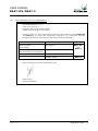
1
USER MANUAL
ELECTROFUSION CONTROL BOX
MODELS BEAT-MV/BEAT-2
Edition: February 2012
R evision N o. 4
Publication: M U -7 8-0 8 E
NOTE !
At the time of the publication of this User Manual, the software version
is V. 1.24.
2
The m odifications carried out against the previous revision of this
publication are indicated with 2 on the right m argin.
USER MANUAL
BEAT-MV/BEAT-2
CONTENTS:
Page:
CHAPTER 1:
INTRODUCTION............................................................................
1.1
General....................................................................
1.2
Design Specifications.................................................
1.3
General Inform ation..................................................
1.4
Unit Identification......................................................
1.4.1 Serial num ber stamping.............................................
1.4.2 CE m aking................................................................
1.5
Measures of protection against accidents......................
1.6
Declaration “CE” of conform ity....................................
1.7
Guarantee................................................................
5
5
6
6
7
7
7
8
9
10
CHAPTER 2:
DESCRIPTION OF THE ELECTROFUSION UNIT...................................
2.1
General....................................................................
2.2
Front part.................................................................
2.3
Side parts................................................................
2.4
Rear part..................................................................
11
11
12
12
13
CHAPTER 3:
MODE OF USE...............................................................................
3.1
Electrofusion procedure..............................................
3.1.1 Scraping pipe surfaces...............................................
3.1.2 Fitting installation......................................................
3.1.3 Unit connection.........................................................
3.1.4 Using the Barcode reader...........................................
3.1.5 Fitting connection......................................................
3.1.6 Entering electrofusion data in the unit..........................
3.1.7 Electrofusion process.................................................
3.1.8 Cooling tim e.............................................................
3.2
Access to other m enus...............................................
3.2.1 Available options.......................................................
3.2.2 INFO option..............................................................
3.2.3 SETUP option............................................................
3.2.4 LAST REVISION option...............................................
3.2.5 SERVICE option.........................................................
14
14
14
14
15
17
18
18
20
21
22
22
22
23
23
23
Edition: February 2 0 1 2
R evision: N o. 4
GENERAL INDEX -
3
USER MANUAL
BEAT-MV/BEAT-2
Page:
CHAPTER 4:
TROUBLESHOOTING......................................................................
4.1
General....................................................................
4.2
Display error m essages..............................................
4.2.1 Input voltage/frequency.............................................
4.2.2 Fitting resistance outside m argin.................................
4.2.3 Interruption by operator.............................................
4.2.4 Output current..........................................................
4.2.5 Electrofusion output voltage.......................................
4.2.6 Protection against internal tem perature........................
24
24
24
24
25
25
25
26
26
CHAPTER 5:
MAINTENANCE..............................................................................
5.1
General....................................................................
5.1.1 Introduction..............................................................
5.1.2 Storage....................................................................
5.1.3 Cleaning...................................................................
5.1.4 Checks.....................................................................
5.2
Control unit..............................................................
5.2.1 Electronic control unit................................................
5.2.2 Updating the program m e software...............................
27
27
27
27
27
27
28
28
28
CHAPTER 6:
TECHNICAL CHARACTERISTICS.......................................................
6.1
Electrofusion control unit............................................
6.1.1 General specifications................................................
6.1.2 Generator specifications.............................................
6.2
Size and weight.........................................................
6.2.1 W eights and dim ensions.............................................
6.2.2 Accessories...............................................................
29
29
29
30
30
30
30
Edition: February 2 0 1 2
4
- GENERAL INDEX
R evision: N o. 4
USER MANUAL
BEAT-MV/BEAT-2
CHAPTER 1: INTRODUCTION
1.1
GENERAL
The electrofusion units BEAT-MV and BEAT-2 are designed to carry out polyethylene
(PE) pipe/fittings joints through electrofusion fittings with a range of 8 V to 48 V
electrofusion voltage.
This User Manual corresponds to the following m odels:
BEAT-MV
Electrofusion unit which
m anually. No traceability.
the
electrofusion
param eters
are
entered
BEAT-2
Electrofusion unit that the electrofusion param eters can be entered
m anually or by barcode system . No traceability.
The BEAT-MV electrofusion unit receives the relevant data of the fitting via operator’s
m anual introduction: VOLTAGE and TIME from the fitting m anufacturer. Take into account
that som e fitting m anufacturers provide different fusion tim es according to am bient
tem perature. Refer to the fitting m anufacturer’s instructions.
The BEAT-2, in addition of the data m anual input is also able to enter the electrofusion
param eters by means of a barcode automatic recognition system .
These m odels can be optionally supplied as AR Series (High Perform ance) with the sam e
original technical specifications, except for having a higher duty cycle. The AR series is
especially indicated for ongoing electrofusion of large size fittings and for very hot
climates.
The technical data contained in this Manual are purely inform ative and m ay be changed
at anytim e. ACUSTER BAHISA, S.L.U. declines all responsibility for claim s arising from
m isuse of the data contained herewith and/or errors or om issions detected after
publication.
This Manual m ust be considered as part of the unit.
Edition: February 2 0 1 2
R evision: N o. 4
INTRODUCTION -
5
USER MANUAL
BEAT-MV/BEAT-2
1.2
DESIGN SPECIFICATIONS
The electrofusion units BEAT-MV and BEAT-2 are designed according to the following
specifications:
C
ISO 12176-2
C
ISO/TR 13950
Equipm ent for fusion jointing polyethylene system s.
Part 2: Electrofusion.
Plastic pipes and fittings: autom atic recognition of
electrofusion system s.
The BEAT-2 accepts all the identifications which correspond to the above listed
Specifications. All the fittings can be fused by electrofusion if the m anufacturer encloses
the program m ed bar code system in accordance with ISO/TR 13950.
1.3
GENERAL INFORMATION
The developm ent, docum entation, production, tests and shipping of the products herewith
described have been m ade:
M
M
Com plying with the respective safety rules, and
In accordance with the requirem ents of quality guarantee.
W ARNING !
The electrofusion control box can only be opened by the Grupo Acuster’s
After-sales Service. In the case of the front and back covers opening or
com ing apart, parts of electrical com ponents which are not covered m ay
be left exposed.
Only qualified personnel are authorised to intervene both for fusion and
repairs. These qualified personnel must be familiar with all the safety
m easures, potential dangers and m aintenance rules described in this
Manual.
The safe use of the products described requires an appropriate means of
transport, storage, installation and use, a careful handling and the
preestablished periodical maintenance follow-up.
Edition: February 2 0 1 2
6
- INTRODUCTION
R evision: N o. 4
USER MANUAL
BEAT-MV/BEAT-2
1.4
UNIT IDENTIFICATION
1.4.1
Serial Num ber Stam ping:
The electrofusion units BEAT-MV and BEAT-2 are identified by m eans of their own
identification plate.
ACUSTER S.L.
QUALITY CONTROL
CONTROL DE CALIDAD
MACHINE No.
EQUIPO Nº
" REVISIONES
MAINTENANCE
REVISIONS
"
Juan de la C ierva, 1 - Políg. Ind. nº 1
Telf. + 34 93 4703070 - Sant Just D esvern (Barcelona)
MANUFACTURER'S
ADDRESS
Figure 1
The quality control identification plate includes the fusion control box serial num ber. The
plate includes room for future m aintenance date stam ping.
1.4.2
"CE" m arking:
The electrofusion unit is supplied with the appropriate plate with the "CE" m ark, as the
European Com m unity norm indicates on the new Machine Security Regulation (Board
98/37/CE, dated 22nd June 1998).
ACUSTER S.L.
C E
" MODELO:
"
Nº SERIE
Juan de la C ierva, 1 - Políg. Ind. nº 1
Telf.+ 34 93 4703070 - S ant Just Desvern (Barcelona)- S PA IN
Figure 2
Edition: February 2 0 1 2
R evision: N o. 4
INTRODUCTION -
7
USER MANUAL
BEAT-MV/BEAT-2
1.5
MEASURES OF PROTECTION AGAINST ACCIDENTS
Please go by the following security m easures:
M
Keep the fusion control box out of the reach of non authorised personnel, non
qualified personnel and children.
M
Protect the control unit from water, rain, snow, etc.
M
Protect the electrofusion cables and the cable that goes to the power supply of
cutting objects.
M
All damaged cables m ust be replaced im m ediately by the After-Sales Service of
Grupo Acuster.
M
Always plug the control box to a power supply provided with differential and
ground connection.
M
Do not expose the fusion control box to heavy weights. All slight dam age caused
to the external fram e or to other elements will have to be replaced im m ediately
by the After-Sales Service of Grupo Acuster.
M
The fusion control boxes which are not being used must be kept out of the reach
of the non authorised personnel. They will have to be kept in room s of low
hum idity degrees and of restricted access.
M
Always use adequate working clothes.
For outside work, it is recom mended to use rubber gloves and boots with
insulating soles. In wet areas, this advice is essential.
M
Before using the fusion control box, its external condition will have to be checked,
as well as its working condition. All components m ust be correctly assem bled in
order to guarantee the correct functioning of the unit.
M
The dam aged com ponents must be repaired or replaced by the After-Sales Service
of Grupo Acuster.
M
The fusion control box can only be opened by the After-Sales Service of Grupo
Acuster.
M
Should the fusion control box not work properly, it will have to be sent
im m ediately to the After-Sales Service of Grupo Acuster.
Edition: February 2 0 1 2
8
- INTRODUCTION
R evision: N o. 4
USER MANUAL
BEAT-MV/BEAT-2
1.6
DECLARATION "CE" OF CONFORMITY
ACUSTER BAHISA, S.L.U.
Juan de la Cierva, 1
Polígono Industrial del Sud-Oest
08960 Sant Just Desvern (Spain)
declare under our sole responsibility that the electrofusion units BEAT-M V
and BEAT-2, to which this declaration relates is in conform ity with the
following Directives and also the following relating standards:
Directive
Related Specification
2006/95/CEE
Low Voltage
EN 60335-1
2004/108/CEE
Electrom agnetic com patibility
EN 61000-6-2; EN 61000-6-3
M odel
BEAT-M V
&
BEAT-2
ISO 12176-2
ISO/TR 13950
BEAT-2
Sant Just Desvern, 20th Septem ber 2010
Jaum e Puig
General Manager
E d ition : Fe bru a ry 2 0 12
R e vision : N o. 4
INTRODUCTION -
9
USER MANUAL
BEAT-MV/BEAT-2
1.7
GUARANTEE
Guarantee Declaration:
All the electrofusion units BEAT-MV and BEAT-2 are manufactured from high
quality m aterial and have been subjected to rigorous tests for resistance and
working order as well as passing all the quality control tests required by the
applicable norm atives (see "CE" Declaration of conform ity).
Regardless of whether an incident might occur during the period of guarantee,
we recom m end careful reading of the following general guarantee conditions.
General conditions of Guarantee:
1.
ACUSTER BAHISA, S.L.U. guarantees that this product has no
m anufacturing defect at the tim e of its purchase and extends this
guarantee for the period of TW O years.
2.
If the product proves defective during this period, due to the materials
or its assem bly, it will be repaired free of charge, including the cost of
m aterials and labour at Grupo Acuster’s Technical Service.
3.
The Guarantee is not valid in the following cases:
W hen the fault in the product is a result of:
!
!
!
!
4.
Abuse or incorrect use of the unit
Not following the instructions specified in this User Manual for
connecting to a group generator.
Repairs carried out without authority from Grupo Acuster (the
taking apart or breaking of the unit's seal imm ediately renders
the guarantee invalid).
Accidents, natural disasters (including lightning, water action
etc) as well as any cause beyond Grupo Acuster’s control.
In all claims against this guarantee, inform ation relating to the m odel,
date of purchase, Serial num ber and any other additional inform ation
m ust at all tim es be stated.
Edition: February 2 0 1 2
10 - INTRODUCTION
R evision: N o. 4
USER MANUAL
BEAT-MV/BEAT-2
CHAPTER 2: UNIT’S DESCRIPTION
2.1
GENERAL
The electrofusion units BEAT-MV and BEAT-2 are m ade up of an ABS plastic case
assem bled on a steel tubular fram e, a master switch, fuse holder, the m ains and
electrofusion cables. Additionally the BEAT-2 is fitted with a serial connector for the
connection of optic pen or scanner.
The front part is form ed by a m em brane which incorporates tactile push-buttons to enter
the data and a back-lit LCD display.
Inside, the unit is form ed by a processor board (CPU), transform er, in addition to all of
the electronics necessary for the electrofusion process, current and voltage controls.
Figure 3a: BEAT-MV general view
Figure 3b: BEAT-2 general view
Edition: February 2 0 1 2
R evision: N o. 4
MACHINE’S DESCRIPTION - 11
USER MANUAL
BEAT-MV/BEAT-2
2.2
FRONT PART
The front part of BEAT-MV and BEAT-2 electrofusion unit is formed by a silkscreened
plastic m embrane which incorporates m em brane type tactile push-buttons. The display
is located on the upper left side.
W here:
1
2
3
4
5
6
Front cover
Tubular fram e
Mem brane with push-buttons
Display
Seal plug
Adhesive of model: MV or 2
Figure 4
2.3
SIDES
On the right side of the BEAT-MV and BEAT-2 electrofusion unit (looking at it from the
front), the following elements are located:
1
2
3
Master switch
Fuse holder
Power cable
Figure 5
Edition: February 2 0 1 2
12 - MACHINE’S DESCRIPTION
R evision: N o. 4
USER MANUAL
BEAT-MV/BEAT-2
On the left side of the BEAT-MV and BEAT-2 electrofusion unit (looking at it from the
front), the following elements are located:
1
2
3
4
Electrofusion cables
Serial connector for optic pen/
scanner (BEAT-2)
RT sensor
Guarantee seals
Figure 6
2.4
REAR
The unit’s identification plates are located on the rear cover of the BEAT-MV and BEAT-2
units.
1
2
3
4
5
6
Technical specifications sticker
Seal plug
Docum ent holder bag
Buzzer
Service revisions plate
“CE” plate
Figure 7
Edition: February 2 0 1 2
R evision: N o. 4
MACHINE’S DESCRIPTION - 13
USER MANUAL
BEAT-MV/BEAT-2
CHAPTER 3: MODE OF USE
3.1
FUSION PROCEDURE FOR ELECTROFUSION FITTINGS
3.1.1
Scraping pipe surfaces:
First clean the surface to be scraped with a clean lint-free dry cloth. The length to be
cleaned will depend on the size of the fitting to be used, adding a m inim um additional
m argin of 50 m m on each end.
Scrape the area of the pipe or pipes where the fitting to be joined will be installed. The
length of the scraping should be greater than that of the fitting.
IMPORTANT !
The scraping of the pipe should generate swarfs. This ensures the
elim ination of the pipe’s most exterior oxidation, which would otherwise
lead to a dissatisfactory electrofusion joint.
Next clean the scraped area with a degreasing towel or with a clean, dry white cloth
(which does not shed lint), dam pened with isopropanol or recom m ended PE solvent.
3.1.2
Fitting installation:
For joints of tapping saddles and branch saddles, place a rounder on each side of the
scraped area if the fusion is perform ed over a bar pipe. If the joint is performed over a
pipe from a roll, the placem ent of an aligner-rounder tool is indispensable. Next install the
fitting over the pipe.
If the fitting to be jointed is a coupler, reducer or elbow, rem ove it from its wrapping, and
without touching its interior, install it on the scraped and cleaned pipe. Now assem ble the
aligner and the other specially-prepared pipe or fitting.
Electrofusion joints should only be carried out by qualified staff.
Protect the area where electrofusions area carried out
from adverse weather conditions, such as rain, snow
or wind. Adm issible tem peratures range from -5EC to
+45EC. In order to achieve a uniform tem perature in
the whole diam eter of the pipes, protect the fusion
area against sunrays or bad weather.
The quality of the joint depends substantially on the
care taken in the previous preparation tasks
(scraping, degreasing, etc).
Figure 8
Edition: February 2 0 1 2
14 - MODE OF USE
R evision: N o. 4
USER MANUAL
BEAT-MV/BEAT-2
3.1.3
Unit connection:
Connect the unit to a 230 V ± 15% /50-60 Hz mains source (or to the corresponding
voltage, according to m arket requirem ent) of alternating current. For generator group
specifications, please refer to CHAPTER 6: TECHNICAL CHARACTERISTICS.
IMPORTANT NOTES !
Connection to a generator: the generator electric connection where
the control box m ains is plugged must be norm alized and fitted with
differential and ground pin. Refer to the generator’s User Manual.
Connection to the m ains: the building electric installation where the
control box mains is plugged m ust be fitted with earth connection as
well as circuit breaker.
Do not unplug the m ains pulling from the cable.
BEAT-2: because the unit allows the use of an optic pen or scanner
indistinctly, connect the barcode reader to use in order to have its
autom atic recognition.
Checking the fitting connection cable term inals before starting up the
unit is advised. There are different types of adopters depending on the
type pf fitting to be used.
Ø
Set the m aster switch in the ON position.
BEAT-XX
V v.vv UK
BEAT-XX:
No.xxxx:
V v.vv:
UK:
dd/m m /yy:
No.xxxx
dd/m m /yy
The display backlight will be enable, an acoustic signal
heard and the following inform ation will appear:
m odel, BEAT-MV or BEAT-2
unit serial num ber
software version
Letters of the active language
current date
Once the display time has elapsed (3 seconds), the unit will display the following screen.
Possible initial m essages:
TECHNICAL MACHINE SERVICE
If the programmed warning date for the Technical Machine Service in the unit has expired,
the display will show:
REV. VALID UNTIL
dd/m m /yy
The unit will emit an acoustic signal and a message will
appear in the display along with the date of the next check.
If the date dd/m m /yy has not expired yet, press START to confirm and proceed to the
next screen (regardless of the existing locking set up of the unit).
Edition: February 2 0 1 2
R evision: N o. 4
MODE OF USE - 15
USER MANUAL
BEAT-MV/BEAT-2
If the date dd/m m /yy has already expired but the unit is set up without locking, by
pressing START you will be able to m ove to the next screen. However, if the unit is set
up with locking subsequently the unit will not be able to be used until the TMS has been
carried out.
AMBIENT TEMPERATURE OUT OF RANGE
If the am bient tem perature is not within -20°C and 50°C [from software version v. 1.21
(previous software versions -15°C and 50° C)] or the tem perature sensor is defective,
with data entry via bar code the following m essage will be displayed:
TEMPERATURE
OUT OF RANGE
Pressing the key START/VALIDATE
switches to m anual m ode.
automatically
NOTE: In the case of faulty probe, send the unit to the Grupo Acuster’s After-sale Service.
INTERNAL FAULT
If the software detects that there is a voltage output through the electrofusion cables out
of the electrofusion cycle, the display shows the following m essage:
SERIOUS TROUBLE
TURN OFF UNIT
The unit will be blocked and the buzzer will be permanently
activated. Switch off immediately the unit.
NOTE: If case to have an electrofusion fitting connected, check if it has suffered dam age.
Send the unit to the Grupo Acuster’s After-sale Service.
LOW BATTERY
In case to detect a battery voltage below the m inim um required, the display will indicate:
SERVICE
FLAT BATTERY
Send the unit to the Grupo Acuster’s After-sale Service
for the replacem ent of the battery.
Pressing the START button, the display shows the date and tim e to update it (refer to
paragraph DATE/TIME of section 3.2.4 of this Manual). This update will keep for som e
tim e if the battery is not replaced, especially with the unit disconnected from the m ains.
From the tim e the unit is started up, a verification of the input voltage is perform ed. If the
voltage registered by the unit is above or below the tolerance allowed (195 - 265 V), one
of the following m essages will appear on the display:
POW ER SUPPLY ERROR
265V
65Hz
Appears when the input voltage or frequency is over
265 Vac / 65 Hz, respectively.
POW ER SUPPLY ERROR
195V
45Hz
Appears when the input voltage or frequency is under
195 Vac / 45 Hz, respectively.
Check the power supply (group) and correct the defect. It is not necessary to switch the
unit off and switch it on again to refresh the input voltage.
Edition: February 2 0 1 2
16 - MODE OF USE
R evision: N o. 4
USER MANUAL
BEAT-MV/BEAT-2
3.1.4
Using the Barcode Reader (BEAT-2):
If you read the different data (operator’s ID, job ID, fittings, pipe, etc) by using optical
m eans (optic pen or scanner, indistinctly), connect the reader device into the
corresponding connector and slide it (barcode reader) our put it in front of the barcode
data (scanner).
ATTENTION !
The scanner should be correctly setup. In case no data is captured by the
device, carry out the following barcode reading.
Software version # v. 1.23
Software version $ v. 1.24
Optic pen: The barcode reader pen works with greater efficiency when gently slid along
the barcode and when the inclination in relation to the vertical is kept between 10 and
40º. However, the pen’s working angle is bigger: it can be used between 0 and 50º, in
relation to the vertical.
The displacement speed during the reading is also a factor to be borne in m ind (as a
general rule, slide the reader neither too slowly nor too fast).
Laser scanner: W hen reading, the connected scanner em its a red laser line of a particular
length. To capture the barcode data, place the scanner so that the laser line coincides
longitudinally with the barcode. The distance will depend on the size of the barcode to
read. Once the scanner has been placed in position, the laser line will stop flashing and
rem ain fixed. W hen this happens, press any of the three buttons on the top of the
scanner.
Figure 9a: Exam ple of using the optic pen
Figure 9b: Exam ple of using the laser scanner
Edition: February 2 0 1 2
R evision: N o. 4
MODE OF USE - 17
USER MANUAL
BEAT-MV/BEAT-2
3.1.5
Fitting connection:
Connect the unit cable connectors in the fitting term inals to be jointed. The contact
surfaces of both the fitting’s term inals and the cable connectors m ust always be clean.
NOTE !
We advise you to always use adapters, even
though the connection to the fitting m ay be m ade
directly. Doing so, the cable term inals are
protected, do not wear out, burn, etc.
It is recom m end refraining from electrofusion if the exterior tem perature
is below -10°C or above +45°C.
3.1.6
Entering electrofusion data in the unit:
Ù
BEAT-MV/BEAT-2: Entering joint data without barcode: via the keyboard.
BEAT-2 only: Click one of the 4 arrows. The display will show the following screen:
BEAT-2
23°C
FUSION DATA?
W here 23°C corresponds to the am bient tem perature
(informative).
Enter voltage. Press the Æ and Å arrows to m ove the cursor to a different field and the
Ç and È arrows to select the values.
FUSION DATA:
VOLTAGE(Volt):
23ºC
$40.0
40.0 Volt by default.
The electrofusion voltage should be betw een 8 and 48 V.
Press START/VALIDATE to pass to the next screen.
Enter the tim e indicated by the fitting m anufacturer, bearing in m ind the correction given
according to the am bient tem perature (according to the manufacturer). Press the Æ and
Å arrows to m ove the cursor to a different field and the Ç and È arrows to select the
values.
FUSION DATA:
TIME(s):
23ºC
$000
“0000" by default.
Maxim um perm itted tim e of 5940 seconds (99 m inutes).
Press START/VALIDATE to pass to the next screen.
SCRAPED & CLEANED ?
<YES>
Does not contem plate it being <NO>.
Edition: February 2 0 1 2
18 - MODE OF USE
R evision: N o. 4
USER MANUAL
BEAT-MV/BEAT-2
Click the START/VALIDATE key. The following m essage will appear:
PRESS <START>
TO BEGIN
Ï
BEAT-2:
Click the START/VALIDATE key to hear an acoustic
signal and the electrofusion cycle will begin.
Reading the fitting’s barcode using optic pen or scanner.
Read the fitting’s barcode with the optic pen or scanner connected to the serial connector.
W ARNING !
Make sure you always read the barcode corresponding to the fitting to be
electrofused. Should you not record the fitting’s data, this could cause
errors in the electrofusion process that would have repercussions on the
quality and reliability of the joint.
If the barcode or reading were incorrect.
FUSION DATA:
W RONG DATA
Error m essage.
Two acoustic signals are em itted and it returns to the start.
W hen the data have been satisfactorily captured, the screen will show the following
m essage:
FUSION DATA: I AG
d20 40,0V 34s
Inform ation captured.
W here it involves a (I) Agru coupler of diam eter 20, 40 Volt and 34 seconds (nom inal).
Main sym bols used (for the full list, please see ISO/TR 13950):
I
.t.
[
Monofilar coupler
Saddle
Single socket
Y
T
C
Reducer
Tee
Elbow
Click the START/VALIDATE key to pass to the following screen.
SCRAPED & CLEANED ?
<YES>
Does not contem plate it being <NO>.
Click the START/VALIDATE key. The following m essage will appear:
PRESS <START>
TO BEGIN
Click the START/VALIDATE key to hear an acoustic
signal and the electrofusion cycle will begin.
Edition: February 2 0 1 2
R evision: N o. 4
MODE OF USE - 19
USER MANUAL
BEAT-MV/BEAT-2
3.1.7
Ú
Electrofusion process:
The unit has initiated the electrofusion cycle. The time and countdown till you get to zero
will com e on the display in seconds. The START/VALIDATE led will flash during the whole
cycle.
BEAT-MV/BEAT-2 (Manual)
ON PROCESS...
vv.vV TTTTs
tttts
W here:
vv.vV:
TTTTs:
tttts:
BEAT-2 (Barcode)
The electrofusion cycle
is being initiated.
ON PROCESS...
d20 40.0V 34s
I AG
Where is referred to an Agru
coupler of diam eter 20, 40 Volt
and 34 seconds.
Electrofusion voltage entered.
Electrofusion tim e entered.
Countdown of tim e TTTT till zero
seconds are com e on the display.
The input voltage is checked during the start up phase of the electrofusion cycle. During
this phase it is considered that the unit – specially for a generator – will stabilize its
energy supply. The unit verifies if the input voltage and electrofusion current are within
the established range (voltage: 165-265 V; current >2A <70A). Once overpassed this
initial phase, the above m entioned voltage and current values are continuously checked
during the whole electrofusion cycle.
If electrofusion data were entered using a barcode (BEAT-2 only), the unit should also
check that the fitting resistance corresponds to that of the fitting connected and that it is
within the tolerances assigned by the m anufacturer. This will be done when the unit starts
the electrofusion cycle.
If the resistance is not correct, the display will show the following m essages, where
appropriate:
FAILURE OF FITTING
RESISTENCE TOO HIGH
W hen the fitting resistance read by the unit is higher
than allowed.
FAILURE OF FITTING
RESISTENCE TOO LOW
W hen the fitting resistance read by the unit is lower
than allowed.
Check the fitting, connections, etc., and restart the cycle.
W hen the fusion cycle has ended satisfactorily, the display will show the following
m essage:
BEAT-XX
23ºC
CORRECT FUSION
The upper m essage
displayed alternately.
is
COOLING TIME
CORRECT FUSION
10'
The top line of the display alternately shows the m essages listed above (only BEAT-2 and
with an introduction of the electrofusion data via bar code).
W here 23°C corresponds to room tem perature (inform ative) and 10' corresponds to the
cooling tim e indicated in the fitting bar code.
Edition: February 2 0 1 2
20 - MODE OF USE
R evision: N o. 4
USER MANUAL
BEAT-MV/BEAT-2
The fusion process can be stopped at any time by pressing the STOP key. The cycle will
then stop and the display will show the following m essage:
<STOP> PRESSED
xxxxs
W here xxxxs is the rem aining cycle tim e at the
m om ent of stopping.
If other incidents occur during the fitting electrofusion process, the process will stop and
the corresponding m essage will be shown on the display. For further inform ation, see
CHAPTER 4: TROUBLESHOOTING.
3.1.8
Û
Cooling tim e:
Once the electrofusion cycle is com pleted satisfactorily, leave a m inim um cooling tim e as
provided by the fitting’s m anufacturer before proceeding to disassemble the equipm ent.
Repeat the procedure described for a new electrofusion process.
Edition: February 2 0 1 2
R evision: N o. 4
MODE OF USE - 21
USER MANUAL
BEAT-MV/BEAT-2
3.2
ACCESS TO OTHER MENUS
3.2.1
Available options:
You can access other m enus by starting up the unit at the m ain power supply, clicking the
START/VALIDATE key.
There are a total of four menu options: INFO/SETUP/LAST REVISION/SERVICE, accessed
by sequentially clicking the È key. The first screen is:
>INFO
SETUP
Use the Ç and È keys to m ove to the selected option
and validate with the START key.
Click on È to see:
INFO
>SETUP
Use the Ç and È keys to m ove to the selected option
and validate with the START key.
Click on È to see:
SETUP
>LAST REVISION
Use the Ç and È keys to m ove to the selected option
and validate with the START key.
Click on È to see:
LAST REVISION
>SERVICE
Use the Ç and È keys to m ove to the selected option
and validate with the START key.
And click È to once again see the first option.
3.2.2
INFO option:
To validate the following INFO m enu option,
>INFO
SETUP
Use the Ç and È keys to m ove to the selected option
and validate with the START key.
V v.vv UK
0000
LAST SERV: dd/m m /yy
The display screen shows the following inform ation:
V v.vv is the software version and UK are the letters of the active language.
0000 indicates the set mode, not available for these m odels (for BEAT-Tr only).
dd/m m /yy corresponds to the date of the latest revision m ade in the unit.
Click <STOP> to exit this option.
Edition: February 2 0 1 2
22 - MODE OF USE
R evision: N o. 4
USER MANUAL
BEAT-MV/BEAT-2
3.2.3
SETUP option:
Finally, validate the second and last option of the SETUP menu:
Use the Ç and È keys to m ove to the selected option
and validate with the START key.
INFO
>SETUP
This enables access to the following options: LANGUAGE / DATE/TIME.
Use the Ç and È keys to m ove to the selected option and validate with the START key.
LANGUAGE
The display shows the letters of the active language.
UK
Click the Æ and Å keys to see the other languages loaded in the unit. If you cannot find
the language you want, consult with your distributor.
Click the START/VALIDATE key to accept the option. Click <STOP> to exit this option
without changing the language.
The following option enables you to update the unit’s date and tim e.
$dd/m m /yy
$hh:m m
dd/m m /yy corresponds to the date and hh:mm to the
tim e.
Click the Æ and Å keys to m ove the field and Ç and È keys to m odify values. Once past
the second line, it is not possible to return to the first. You will have to click <STOP> to
restart the change of date/tim e. Click the START/VALIDATE key to accept the option once
you have gone over the 5 fields. Click <STOP> to exit this option without m aking a
m odification.
3.2.4
LAST REVISION option:
Validate the third m enu option of LAST REVISION:
SETUP
>LAST REVISION
Use the Ç and È keys to m ove to the selected option
and validate with the START key.
dd/m m /yy
dd/m m /yy
The display will show the following inform ation:
dd/m m /yy
ON/OFF
It allows to check the date of the last revision (service), the warning date, the date of
expiration of the next service and the unit blocking status (OFF or ON) in this order.
Click <STOP> to exit this option.
3.2.5
SERVICE option:
Finally, validate the last menu option of SERVICE:
LAST REVISION
>SERVICE
Use the Ç and È keys to m ove to the selected option
and validate with the START key.
The last option of the Setup is for exclusive use of the Grupo Acuster’s after-sales service
centres and an access password is required.
To exit from this access to other m enus, stop the unit through the general switch.
Edition: February 2 0 1 2
R evision: N o. 4
MODE OF USE - 23
USER MANUAL
BEAT-MV/BEAT-2
CHAPTER 4: TROUBLESHOOTING
4.1
GENERAL
All m aintenance and repair work of the BEAT-MV and BEAT-2 electrofusion units is to
be carried out by qualified personnel. Full guarantees are obtained by shipping the unit
to the Grupo Acuster’s After-Sales Service, both for the yearly revision and for repairing
any fault that m ay have occurred in the unit.
4.2
DISPLAY ERROR MESSAGES
4.2.1
Input voltage/frequency:
The input voltage/frequency is valued differently according to the process being done at
the tim e.
1.
Verification before fusion process:
If the input voltage/frequency is outside the established tolerances (m in. 195Vac
/ m ax. 265Vac and m in. 45Hz / max. 65Hz, respectively), the screen will show:
2.
POW ER SUPPLY ERROR
194V 44Hz
The values the display shows are refreshed and
correspond to the real input of the unit.
POW ER SUPPLY ERROR
266V 66Hz
The values the display shows are refreshed and
correspond to the real input of the unit.
Verification during electrofusion:
During the fusion cycle the m inimum input voltage m ay be below 195 Vac without
the process being interrupted, but always so long as the required output current
is supplied. Otherwise, the display will show the following message:
POW ER SUPPLY ERROR
xxxxs
160V 42Hz
W here xxxxs corresponds to the rem aining
cycle tim e at the m om ent of stopping.
In the exam ple, 160V is the m inimum voltage detected by the unit.
This error m essage also is enabled when the m aximum input voltage detected by
the unit is higher than 265 Vac. Check the power supply (group), connections,
state of fitting, etc. It is not necessary to restart the unit to refresh the input
voltage.
Edition: February 2 0 1 2
24 - TROUBLESHOOTING
R evision: N o. 4
USER MANUAL
BEAT-MV/BEAT-2
4.2.2
Fitting resistance outside m argins (BEAT-2):
Once the electrofusion process has begun and where data is captured exclusively by
barcodes, if the fitting resistance is higher than the tolerances established by the fitting’s
m anufacturer, the display will show:
FAILURE OF FITTING
RESISTENCE TOO HIGH
If this message persists, send the unit the After-Sales Service to check the calibration of
the resistance m easure.
Once the electrofusion process has begun and where data is captured exclusively by
barcodes, if the fitting resistance is lower than the tolerances established by the fitting’s
m anufacturer, the display will show:
FAILURE OF FITTING
RESISTENCE TOO LOW
If this m essage persists and after checking the that fitting and barcode resistance are
correct, send the unit the After-Sales Service to check the calibration of the resistance
m easure.
4.2.3
Interruption by operator:
If the operator presses the <STOP> key once the electrofusion process has begun, the
display will show:
<STOP> PUSHED
xxxxs
4.2.4
W here xxxxs corresponds to the rem aining
cycle tim e at the m om ent of stopping.
Output current:
If the electrofusion current is excessive, the display will show:
CURRENT TOO HIGH
xxxxs
W here xxxxs corresponds to the rem aining
cycle tim e at the m om ent of stopping.
This m essage appears in the following cases:
1. W hen the connected fitting has a very low resistance, outside the margins.
2. Crossed fitting resistence.
If the electrofusion current is too low, the display will show:
CURRENT TOO LOW xxxxs
W here xxxxs corresponds to the rem aining
cycle tim e at the m om ent of stopping.
Edition: February 2 0 1 2
R evision: N o. 4
TROUBLESHOOTING - 25
USER MANUAL
BEAT-MV/BEAT-2
This m essage appears in the following cases:
1.
2.
3.
4.
4.2.5
Fitting not connected.
Disconnection of the electrofusion terminals.
Cut in the filam ent of the fitting resistance.
If the electrofusion current is lower than 2 A.
Electrofusion output voltage:
If there is a deviation of ± 0,5 V in the output voltage during the electrofusion of the
fitting, the cycle will stop and the display will show:
VOLTAGE FAILURE
xxxxs
W here xxxxs corresponds to the rem aining
cycle tim e at the m om ent of stopping.
This m essage m ay also appear due to poor fitting application (fitting voltage outside
range).
4.2.6
Protection against internal tem perature:
If the electrofusion unit is subm itted to intensive, prolonged operation, especially with
large-diameter fittings with high fusion times, for which the internal tem perature m ay
exceed the m axim um allowed, the following procedure is established:
1.
If after an electrofusion cycle the transform er tem perature is higher than 60ºC,
the transform er and electronics are protected by an internal tem perature sensor
which blocks the unit. If this safety device is activated, the electrofusion under
way will not be interrupted. The display will show the following m essage:
TRAFO TEMPERATURE
TOO HIGH **W AIT**
2.
This m essage will rem ain on the screen until
the internal tem perature falls to 55ºC.
If during an electrofusion process the transform er tem perature reaches 90ºC, the
cycle will stop and the unit will remain blocked until the internal tem perature falls
to 55ºC. The display will show the following message:
TEMPERATURE TOO HIGH
xxxxs
W here xxxxs corresponds to the rem aining
cycle tim e at the m om ent of stopping.
Edition: February 2 0 1 2
26 - TROUBLESHOOTING
R evision: N o. 4
USER MANUAL
BEAT-MV/BEAT-2
CHAPTER 5: MAINTENANCE
5.1
GENERAL
5.1.1
Introduction:
The electrofusion units BEAT-MV and BEAT-2 have been designed and manufactured for
a long life service without the need for costly repairs and adjustm ents. All that is required
is careful handling when loading/unloading and during transport, and in general to keep
the unit clean by following the recom m ended preventive m aintenance. The costs are very
low and are soon written off given that the unit will be fully functional at all tim es.
This section includes a list of general upkeep and m aintenance routine operations. Should
any problem arise please refer to CHAPTER 4: TROUBLESHOOTING point in this User
Manual. However, no action should be taken by unqualified personnel beyond these
troubleshooting m easures in order not to run the risk of seriously dam aging the unit.
5.1.2
Storage:
If the unit is not to be used for a long period of tim e, keep it in its original packing and
protected from dust, m oisture, extrem es of tem peratures, direct sunlight, and so on. The
electrofusion control box could be stored either on the warehouse floor or in pallet racks.
5.1.3
Cleaning:
Clean the electrofusion control box regularly using only a dam p cloth.
NOTICE !
Do not clean the electrofusion control box with water under pressure,
by im mersion in water o with com pressed air.
Do not rub excessively the plastic shell, for it could charge itself with
static electricity.
Should the unit be very dirty, clean it with a bit of alcohol (do not use solvents or cleaning
products containing trichloroethylene).
5.1.4
Checks:
W e recom m end shipping the electrofusion control unit to the Grupo Acuster’s After-Sales
Service for a yearly service.
Edition: February 2 0 1 2
R evision: N o. 4
MAINTENANCE - 27
USER MANUAL
BEAT-MV/BEAT-2
5.2
CONTROL UNIT
5.2.1
Electronic Control Unit:
Besides the exterior cleaning of the casing, there is no specific m aintenance for the
electronic control unit. Tune-ups and adjustm ents should be perform ed by qualified
personnel, or by the Grupo Acuster’s After-Sales Service.
5.2.2
Updating the Program m e Version:
The updating of the BEAT-MV and BEAT-2 electrofusion unit software m ust be perform ed
exclusively by the Grupo Acuster’s After-Sales Service.
Edition: February 2 0 1 2
28 - MAINTENANCE
R evision: N o. 4
USER MANUAL
BEAT-MV/BEAT-2
CHAPTER 6: TECHNICAL CHARACTERISTICS
6.1
ELECTROFUSION CONTROL UNIT
6.1.1
General specifications:
C lassification acc to IS O 12176-2
C onfiguration options
B E A T -M V
B E A T -2
P 2 4U S 1 VK X
P 2 4U S 1 V K A X
Language > M ultilingual (request available languages)
D ate / Tim e
Input voltage
195 Vac to 265 V ac. N om inal voltage: 230 V ac
90 Vac to 140 V ac. Nom inal voltage: 110 V ac
Input frequency
45 H z to 65 H z. N om inal frequency: 50 H z
Electrofusion voltage
8 to 48 V ac galvanically separated
Pow er consum ption
3500 W m axim um
G enerator output perform ance
4.5 kVA unipolar operation; electronic regulation
Protection fuse
Exterior of 20 A at 230 V ac
Exterior of 32 A at 110 V ac
Protection type
Doble isolation IP54 / Series AR: D ouble isolation IP43
D uty factor
W orking tem perature
20 to 100% (depending on the fitting); Series AR: 40 to 100%
Electronic tem perature m onitoring of the unit
M anual
Inform ative, w ith established lim its
(recom m ended acc. to IS O 12176-2 from -10 to 40EC )
Barcode
-20 to 50EC
D isplay
LC D , 2 lines x 20 characters backlight
A coustic w arning
piezoelectric buzzer
Enter fusion data
M anual
Voltage: M ultivoltage
Tim e: U p to 5,940 seconds (99 m inutes)
A utom atic
Barcode acc. to IS O /TR 13950
Front, keys and chassis
O ther features
Pow er cable
Electrofusion cables
O ptic pen/scanner
C onnection of optic pen, scanner
A ccessories
W eight and dim ensions
G reen/grey silkscreen plastic m em brane w ith tactile push buttons and tubular
fram e of 20° of inclination
S oft start and m essage display in case of initial voltage failure
2
3x2.5 m m (S chuko + French type plug) 4 m long
2
3x2.5 m m (230V , 16A Blue acc. to EN 60309 type plug) 4 m long
2
3x4 m m (110V, 32A Yellow acc. to EN 60309 type plug) 4 m long
2
1x16 m m , 4 m long (fem ale term inals of diam eter 4 m m )
N on-intelligent infrared
Laser scanner optional
C om bined TTL / RS -232 special
D ocum ent holder w ith optic pen or scanner and set of 4 and 4.7 m m electrofusion adaptors
H eight: 425 m m ; W idth: 370 m m ; Length: 230 m m
N ett w eight: 23 kg
Edition: February 2 0 1 2
R evision: N o. 4
TECHNICAL CHARACTERISTICS - 29
USER MANUAL
BEAT-MV/BEAT-2
6.1.2
Generator specifications:
Frequency
:
50/60 Hz
Output power
:
4.5 kVA (m inim um )
Voltage
:
230 Vac/110 Vac
Intensity
:
16 A (m in) for 230 Vac
Voltage regulation
:
Preferably electronic
Nett weight
:
23 Kg (including cables and accessories)
Dim ensions
:
Height
W idth
Length
Package exterior dim ensions
Gross approxim ate weight
:
:
440 x 430 x 240 m m
30 Kg
6.2
SIZE AND WEIGHT
6.2.1
W eights and dim ensions:
6.2.2
425 m m
370 m m
230 m m
Accessories:
List of accessories included in the unit:
QTY
DESCRIPTION
1
Docum ent holder
1
User Guide
1
2
2
Optic pen or scanner (BEAT-2 only and depending on the option)
ö 4 m m term inal adaptors
ö 4.7 m m term inal adaptors
Edition: February 2 0 1 2
30 - TECHNICAL CHARACTERISTICS
R evision: N o. 4
USER MANUAL
BEAT-MV/BEAT-2
NOTES
Edition: February 2 0 1 2
R evision: N o. 4
TECHNICAL CHARACTERISTICS - 31